
Related Manuals for SystemAir SysAqua Series


Summary of Contents for SystemAir SysAqua Series
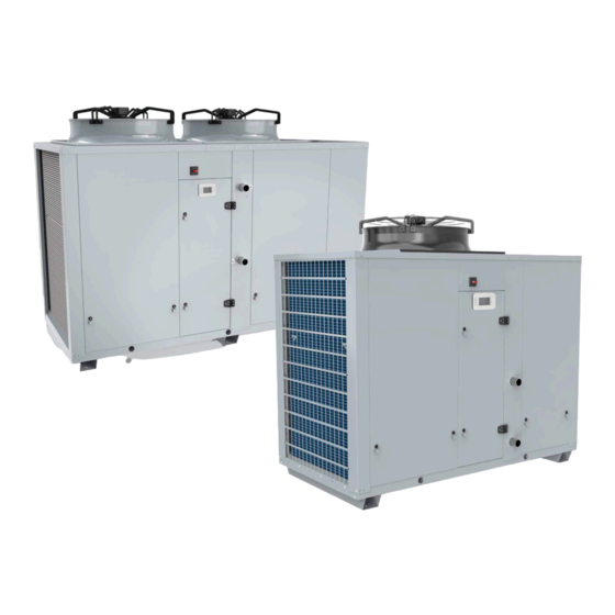
- Page 1 Installation and maintenance manual SysAqua 45 / 55 / 65 / 75 / 90 / 105 / 125 Air Cooled Water Chillers and Heat Pumps 48.5 â 119.1kW 46.8 â 129.8kW...
- Page 3 SysAqua INSTALLATION INSTRUCTION English NOTICE D’INSTALLATION Français INSTALLATIONSHANDBUCH Deutsch ISTRUZIONI INSTALLAZIONE Italiano INSTRUCCIONES DE INSTALACIÓN Español...
-
Page 4: Table Of Contents
2 SysAqua CONTENTS 1. GENERAL RECOMMENDATIONS ................................ 3 1.1. SAFETY DIRECTIONS ............................................3 1.2. WARNING ................................................. 3 1.3. EQUIPMENT SAFETY DATA ..........................................4 2. INSPECTION AND STORAGE ................................5 3. WARRANTY ...................................... 5 4. PRESENTATION ....................................5 5. CONTENTS OF PACKAGE ................................... 6 5.1. -
Page 5: General Recommendations
SysAqua POWER SUPPLY MUST BE SWITCHED OFF BEFORE STARTING WORK IN THE ELECTRIC CONTROL 1. GENERAL RECOMMENDATIONS The purpose of this Manual is to provide users with instructions for installing, commissioning, using and maintaining the units. It also contains instructions on starting up the machine as well as recommendations to avoid bodily injury and risks of damage to the device during its operation. -
Page 6: Equipment Safety Data
4 SysAqua 1.3. EQUIPMENT SAFETY DATA Safety Data R410A Toxicity Skin contact with the rapidly evaporating liquid may cause tissue chilblains. In case of skin contact with In contact with skin the liquid, warm the frozen tissue with water and call a doctor. Remove contaminated clothing and footwear. -
Page 7: Inspection And Storage
SysAqua 2. INSPECTION AND STORAGE At the time of receiving the equipment carefully cross check all the elements against the shipping documents in order to ensure that all the crates and boxes have been received. Inspect all the units for any visible or hidden damage. -
Page 8: Contents Of Package
6 SysAqua 5. CONTENTS OF PACKAGE SysAqua Water filter Bag with the documentation 5.1. OPTIONALS ACCESSORIES Anti-vibration rubber pads Spring pads Isolating valve On opening the carton, check that all the accessories required for installation are present. 6. DIMENSIONS SEE APPENDIX 7. -
Page 9: Handling With A Forklift
SysAqua Caution When handling the SysAqua, beware not to damage the finned coil block. Protect it with cardboard or particle panels. 7.3.1. HANDLING WITH A FORKLIFT When a forklift is used to handle the SysAqua 45/55/65/75/90/105/125 units, lift them only along their width. Place a safety wedge between the unit base and the fork lift truck to avoid damaging the unit’s structure and casing. -
Page 10: Technical Specifications
8 SysAqua 8. TECHNICAL SPECIFICATIONS 8.1. PHYSICAL CHARACTERISTICS Supply voltage 400V / 3~ N / 50Hz Number of refrigerang circuit REFRIGERANT Type R410A Factory charge SEE NAME PLATE COMPRESSORS Type Scroll Number Startup type DIRECT 0/43/ 0/40/ 0/38/ 0/33/ Part load steps 0/50/100 0/45/55/100 57/100... -
Page 11: Refrigeration Specifications
SysAqua 8.2. REFRIGERATION SPECIFICATIONS 8.2.1. REFRIGERANT CIRCUIT DIAGRAM SEE APPENDIX 8.2.2. REFRIGERANT CHARGE Caution This equipment contains fluorinated gas with greenhouse gas effects covered by the Kyoto agreement. The type and quantity of refrigerating fluid per circuit are indicated on the product plate. The installer and end user will get informed on local environmental regulations for the installation, operation and disposal of the equipment ;... -
Page 12: Electric Specifications
10 SysAqua 8.3. ELECTRIC SPECIFICATIONS 8.3.1. SYSAQUA WITH STANDARD FAN 400V / 3~ N / 50Hz Power supply Maximum current 40.20 44.20 59.43 64.43 77.90 85.96 101.96 Fuse rating aM Without pump Total starting current (without soft starter) 133.20 140.20 201.43 206.43 264.90... -
Page 13: Installation
SysAqua 9. INSTALLATION Caution The unit is not designed to withstand weights or stresses from adjacent equipment, pipe work or constructions. Any foreign weight or stress on the unit structure could lead to a malfunction or a degradation with dangerous consequences for personnel and property. In such an event, the warranty shall be null and void. -
Page 14: Clearance
12 SysAqua 9.2. CLEARANCE When choosing the location for the SysAqua, take care to leave sufficient free clearance on all sides to ensure 5 000 easy access for maintenance work. The minimum free clearance dimensions 1 500 indicated must be observed to ensure 1 500 both proper system operation and allow access for maintenance and cleaning. -
Page 15: Hydraulic Links
SysAqua 10. HYDRAULIC LINKS Caution When choosing and installing water pipes, you must consult and observe all current local standards, regulations and instructions. 10.1. MAIN HYDRAULIC CIRCUIT Caution The mains hydraulic circuit will provide a constant water flow on the refrigerating fluid/water plate exchanger and in case of load variation. -
Page 16: Minimum Water Volume Requirements
14 SysAqua 10.3. MINIMUM WATER VOLUME REQUIREMENTS To ensure that the system operates correctly you must use suitably sized and properly routed pipes for the hydraulic links between the SysAqua and the mains network. Proper operation of the regulation and safety devices is ensured only when the water volume is sufficient. -
Page 17: Frost Protection
SysAqua 10.6. FROST PROTECTION If the SysAqua is exposed to ambient temperatures between 1°C and -18°C, protect the water circuit against frost. Caution THE USE OF A GLYCOL-BASED SOLUTION IS THE ONLY EFFECTIVE FROST-PROTECTION MEANS The glycol-based water solution must be sufficiently concentrated to ensure appropriate protection and prevent ice from forming at the minimum outdoor temperatures planned for the installation. -
Page 18: Water Quality
16 SysAqua 10.7. WATER QUALITY The water must be analyzed; the hydraulic network system installed must include all elements necessary for water treatment: filters, additives, intermediate exchangers, drain valves, vents, check valves, etc., according to the results of the analysis. Caution The SysAqua must not run on a network with open loops, likely to cause incidents related to oxygenation, or with non treated table water. -
Page 19: Heat Insulation
SysAqua 10.8. HEAT INSULATION To guarantee proper energy efficiency and compliance with current standards, water pipes passing through uninhabited zones should be properly lagged to retain heat. To achieve correct insulation with conductivity of 0.04 W/mK, lag the pipes with insulating material with a radial thickness between 25mm and 30 mm. -
Page 20: Wiring Diagram And Legend
18 SysAqua 11. WIRING DIAGRAM AND LEGEND 11.1. WIRING DIAGRAM SEE APPENDIX 11.2. LEGEND N805 POL 423.50 POL 688 SE4630 SE4746 models 45 to 55 Control Mono 230V 50Hz +/- 10% SE4629 SE4745 models 45 to 55 Power Tri 400V+N 50Hz +/- 10% SE4632 SE4748 models 65 / 75... -
Page 21: Range And Settings Of Themal Protection / Nominal Intensity Of The Contactors (Classe Ac3)
SysAqua 11.2.3. RANGE AND SETTINGS OF THEMAL PROTECTION / NOMINAL INTENSITY OF THE CONTACTORS (CLASSE AC3) MODELS Range 17-23A 17-23A 24-32A 24-32A 37-50A 37-50A 48-65A Adjustment Range 17-23A 17-23A 20-25A 24-32A 24-32A 24-32A 24-32A Adjustment Range (STD) 2.5-4A 2.5-4A 4-6.3A 4-6.3A 6-10A 6-10A... - Page 22 20 SysAqua VERY IMPORTANT: 3N~400V-50HZ The outdoor unit is equipped as standard with a phase sequence and cut-out controller located in the electrical box. THE LED’s INDICATE THE FOLLOWING CONDITIONS: Green LED = 1 Green LED = 1 Green LED = 0 Yellow LED =1 Yellow LED =0 Yellow LED =0...
-
Page 23: Sysaqua 45 - 55 - 65 - 75 - 90 - 105 - 125
SysAqua 12.1. SYSAQUA 45 - 55 - 65 - 75 - 90 - 105 - 125 The supply cables of the units must be routed up to the section switch through the grommets present at the base of the electrical unit. To ensure proper contact, fit the end pieces adapted to the cross-section of the connecting cable. -
Page 24: Regulation
22 SysAqua 13. REGULATION SysAqua units are fitted with an electronic control system. It provides the command, control and alarm functions. 13.1. ORDER OF PRIORITY FOR CONTROL SYSTEMS The integrated regulator in the SysAqua can be controlled by various interfaces and systems. The order of priority for each drive system is as follows: Timing programming: this scheduling is integrated in the regulator The BMS : the remote supervision transmits it commands according to the communication protocols... -
Page 25: Home Page
SysAqua 13.2.2. HOME PAGE The home page is used to quickly display the state of the machine by Main overview displaying the following information: Current mode Red. H Operating mode ² Entering water T. 42.3°C Water return temperature ² Leaving water T. 45.2°C Water flow temperature ²... -
Page 26: Initial Settings
24 SysAqua 13.3. INITIAL SETTINGS Open the electrical box and check that all circuit breakers are open except for FTC. Before starting up the SysAqua for the first time, the "Installation" menu must be configured. 13.3.1. TIME SETTINGS Caution If the date and time are not set, the unit will function in degraded mode or may not even be able to start. -
Page 27: Defining The Glycol Rate
SysAqua 13.3.3. DEFINING THE GLYCOL RATE Define the type and glycol content present in the installation water circuit. Main Menu Main Menu Status Status Commissioning Commissioning Commissioning Commissioning 1/12 1/12 03.02.2016 03.02.2016 10:40:05 10:40:05 Services Services Language selection Language selection Communications Communications Access... -
Page 28: Configuring Input D2
26 SysAqua 13.4.2. CONFIGURING INPUT D2 During installation, a switch can be connected onto the D2 digital input. The operating mode defined for this input takes priority over all control systems such as the HML, BMS or calendar. SD/N Main Menu Main Menu Status Status... -
Page 29: Selecting The Operating Mode
SysAqua 13.4.4. SELECTING THE OPERATING MODE To launch the unit, the user must select the desired mode in the menu: ² Delegate : the current mode is Main Menu Main Menu Status Status Status Status 1/12 1/12 determined by the BMS or by HMI state HMI state HMI state... -
Page 30: Water Law
28 SysAqua 13.4.6. WATER LAW The configuration of the different water law settings dynamically matches the setpoint according to the outside temperature. The different parameters below for the water law can be set in the installation menu and by a GTC. Main Menu Main Menu Status... - Page 31 SysAqua 13.4.6.2. HEAT MODE The water law replaces the heat mode setpoint with the f function of the OAT outside temperature: water law setpoint = f(OAT) ² Function f is restricted between 20 and 50°C. It is defined by points A, B and C in the graph below. The values indicated are factory values.
-
Page 32: Variable Primary Flow" Option
30 SysAqua 13.4.7. "VARIABLE PRIMARY FLOW” OPTION Main Menu Main Menu Status Status Commissioning Commissioning Services Services Service Service Configuration Configuration Configuration Configuration Access Access Manual control Manual control Deice Deice Pump Pump Pump configuration 1/13 Operation hours Operation hours Circuit control Circuit control Lock out... - Page 33 SysAqua 13.4.7.2. CONSTANT SPEED MODE VS CAPACITY The speed of the pump depends on the capacity of the unit. This speed range is determined during commissioning to adjust the power of the pump to the load drops of the installation. Speed set-point 100% Pump configuration...
- Page 34 32 SysAqua It is necessary to determine the pressure setting to be maintained in the system then set the frequency inverter according to this pressure value. 13.4.7.3.1. DETERMINATION OF THE PRESSURE SETTING The frequency inverter ACS3 displays the reading via the pressure transducer WPT. Set all units in demand to open all the valves (load = 100%).
-
Page 35: Reduced Mode
SysAqua 13.4.8. REDUCED MODE Main Menu Main Menu Status Status Commissioning Commissioning Commissioning Commissioning 1/12 1/12 03.02.2016 03.02.2016 10:40:05 10:40:05 Services Services Language selection Language selection Communications Communications Access Access Glycol protection Glycol protection Auto change over Auto change over Water Law Water Law Reduced mode can have the following... -
Page 36: Alarms
34 SysAqua 13.5. ALARMS Main overview Trigger all circuit breakers. Silence the alarm. Current mode Red. H If at least one alarm or warning is in progress, the alarm button flashes. Entering water T. 42.3°C Press the 'Alarm' button to access the latest current alarm. The Leaving water T. -
Page 37: Schedule
SysAqua 13.6. SCHEDULE The first line displayed shows the current mode at the level of time programming. Main Menu Main Menu Status Status Commissioning Commissioning Commissioning Commissioning 1/12 1/12 03.02.2016 03.02.2016 10:40:05 10:40:05 Services Services Language selection Language selection Communications Communications Access Access... -
Page 38: Commissioning
36 SysAqua 14. COMMISSIONING Caution When performing startup and service, thorough safety precautions shall always be taken. Only qualified individuals should perform these functions. 14.1. PRE-START CHECK LIST Before commissioning the system, you must carry out a certain number of installation checks to ensure that the appliance will operate in the best possible conditions. -
Page 39: Operating Check List
SysAqua 14.2. OPERATING CHECK LIST 14.2.1. GENERAL Cheek for any unusual noises or vibration in the running components. 14.2.2. PHASE ROTATION PROTECTION If the phase of the power supply are not correct, the phase rotation protection device will prevent the machine from starting. -
Page 40: Compressor And Refrigeration System
38 SysAqua 14.2.5. COMPRESSOR AND REFRIGERATION SYSTEM 1. Running check: Start the compressor. Check for any unusual noise or vibration. 2. Operating Pressures: Operate the unit for at last 20 minutes and ensure that the refrigerant pressures are stabilised, and cheek that they are within the normal operating ranges. 3. -
Page 41: Maintenance
SysAqua 17. MAINTENANCE Caution The user is responsible for ensuring that the unit is in perfect working order and that the technical installation and minimum maintenance operations have been performed by a qualified technician in accordance with the procedures described in the present manual. Depending on actual operational constraints and regulatory changes, the installer might recommend increased maintenance operations and more frequent inspections. -
Page 42: Periodic Table Of Service And Maintenance
40 SysAqua 17.2. PERIODIC TABLE OF SERVICE AND MAINTENANCE month months months months months TASKS PER COMPONENTS ACTIONS Recommended inspection and maintenance interval 1 - Casing Control possible contaminations, damage Clean and repair if required. and/or corrosion. Check the possible presence of water Clean and look for the cause, then ... - Page 43 SysAqua month months months months months TASKS PER COMPONENTS ACTIONS Recommended inspection and maintenance interval 3.10 Check filter cleanliness. Clean Check that the hydraulic circuit is filled 3.11 properly Check the condition of the expansion 3.12 tank (presence of excess corrosion, or gas Replace if required.
-
Page 44: Maintenance Procedures
42 SysAqua 17.3. MAINTENANCE PROCEDURES 17.3.1. REFRIGERANT CIRCUIT This equipment must be submitted to sealing checks minimum once per year, by a professional authorized to perform such an operation. Refer to national requirements for the frequency of these checks. Caution Never use the compressor as a vacuum pump to drain the installation. -
Page 45: Hydraulic Circuit
SysAqua 17.3.1.4. AIR COOLED CONDENSER Caution Fin edges are sharp and can cause injury hazard. Avoid contact with them. Condenser coils are composed of copper tubes and aluminium fins. In case of leaks due to damage or shock, the coils must be repaired by one of the authorized Support Centres. To guarantee the best possible operation of the condenser bank, the condenser surface must be maintained as clean as possible, and it must be void of foreign materials (leaves, wires, insects, slag, etc.). -
Page 46: Winter Protection
44 SysAqua 17.3.3. WINTER PROTECTION In winter, after a general stoppage of the installation or a regulation malfunction, the water contained in the hydraulic circuit may start freezing. To prevent any problems if the hydraulic circuit is not glycolated, it is recommended to fully drain any circuits not used and to pressurize them with nitrogen or protect them by adding an anti-freeze solution or other measures. -
Page 47: Trouble Shooting
SysAqua 18. TROUBLE SHOOTING Problem Probable cause Solution Insufficient refrigerant fluid charge. Top up the refrigerant fluid charge. Unit operates continuously but without Clogged dehumidification filter. Replace the dehumidification filter. generating cooling Reduced output from one or both circuits Check the compressor valves and change them if necessary. Increase the setting. - Page 48 46 SysAqua Problem Probable cause Solution Presence of a leak. Identify and repair the leak. Circuit stoppage further to the low pressure Insufficient refrigerant fluid charge. Top up the refrigerant fluid charge. thermostat being activated. Pressostat operating fault. Replace the pressostat. Incorrect operation of the high pressure Check the operation of the pressostat.
- Page 49 APPENDIX / ANNEXE / ANLAGE / ALLEGATO / ANEXO APPENDIX ANNEXE ANLAGE ALLEGATO ANEXO...
- Page 50 APPENDIX / ANNEXE / ANLAGE / ALLEGATO / ANEXO APPENDIX DIMENSIONS ..............III HYDRAULIC PUMPS CURVES ........XVII TTS - POWER - POL688 ............XXXVIII TTS + HPF - CONTROL - POL423......... XXXIX SYSAQUA 45 - 55 .................III SYSAQUA 45 ..................XVII TTS + HPF - POWER - POL423 ..........
- Page 51 APPENDIX / ANNEXE / ANLAGE / ALLEGATO / ANEXO DIMENSIONS DIMENSIONS ABMESSUNGEN DIMENSIONI DIMENSIONES SYSAQUA 45 - 55 Side view Front view Side view Ø2" WATER INTLET OUTLET Top view 2180 Bottom view Side view Front view Side view Ø2" WATER INTLET OUTLET...
- Page 52 APPENDIX / ANNEXE / ANLAGE / ALLEGATO / ANEXO SYSAQUA 45 - 55 WITH BUFFER TANK Side view Front view Side view WATER OUTLET Ø2" INTLET 1264.5 Top view 2680 Bottom view Side view Front view Side view WATER OUTLET Ø2"...
- Page 53 APPENDIX / ANNEXE / ANLAGE / ALLEGATO / ANEXO SYSAQUA 65 - 75 Side view Front view Side view WATER INTLET Ø2" OUTLET Top view 2180 Bottom view Side view Front view Side view WATER INTLET Ø2" OUTLET Top view 2180 Bottom view SysAqua...
- Page 54 APPENDIX / ANNEXE / ANLAGE / ALLEGATO / ANEXO SYSAQUA 65 - 75 WITH BUFFER TANK Side view Front view Side view WATER OUTLET Ø2" INTLET 1264.5 Top view 2680 Bottom view Side view Front view Side view WATER OUTLET Ø2"...
- Page 55 APPENDIX / ANNEXE / ANLAGE / ALLEGATO / ANEXO SYSAQUA 90 - 105 - 125 Side view Front view Side view Ø2"1/2 WATER INTLET OUTLET Top view 2180 Bottom view Side view Front view Side view Ø2"1/2 WATER INTLET OUTLET Top view 2180 Bottom view...
- Page 56 APPENDIX / ANNEXE / ANLAGE / ALLEGATO / ANEXO SYSAQUA 90 - 105 - 125 WITH BUFFER TANK Side view Front view Side view WATER OUTLET Ø2"1/2 INTLET 1265 Top view 2680 Bottom view Side view Front view Side view WATER OUTLET Ø2"1/2...
- Page 57 APPENDIX / ANNEXE / ANLAGE / ALLEGATO / ANEXO DUCT OUTLET DIMENSIONS SYSAQUA 45 - 55 2180 2680 1088 1088 Ø1065 Ø1000 SysAqua...
- Page 58 APPENDIX / ANNEXE / ANLAGE / ALLEGATO / ANEXO SYSAQUA 65 - 75 2180 2680 2172 2172 Ø955 Ø900 SYSAQUA 90 - 105 - 125 2680 2180 2172 2172 1075 1075 Ø1065 Ø1000 X SysAqua...
- Page 59 APPENDIX / ANNEXE / ANLAGE / ALLEGATO / ANEXO SysAqua...
- Page 60 APPENDIX / ANNEXE / ANLAGE / ALLEGATO / ANEXO REFRIGERANT CIRCUIT DIAGRAM SCHEMA DU CIRCUIT FRIGORIFIQUE KÄLTEKREISLAUFDIAGRAMM SCHEMA DEL CIRCUITO REFRIGERANTE ESQUEMA DEL CIRCUITO FRIGORIFÍCO Deutsch English Français M1/2 Compressors 1 et 2 M1/2 Compresseurs 1 et 2 M1/2 Verdichter 1 und 2 Model 45 symmetric Modèle 45 symétrique...
- Page 61 APPENDIX / ANNEXE / ANLAGE / ALLEGATO / ANEXO SYSAQUAL WATER SYSAQUAH WATER SysAqua XIII...
- Page 62 APPENDIX / ANNEXE / ANLAGE / ALLEGATO / ANEXO HYDRAULIC CIRCUIT DIAGRAM SCHEMA DU CIRCUIT HYDRAULIQUE HYDRAULISCHER SCHALTPLAN SCHEMA CIRCUITALE IDRAULICO ESQUEMA CIRCULAR HIDRÁULICO Deutsch English Français RECOMMENDED INSTALLATION INSTALLATION RECOMMANDEE EMPFOHLENE INSTALLATION Connexion flexible Connexion flexible Schlauchverbindung Drain valve Vanne de vidange Ablassventil Globe valve...
- Page 63 APPENDIX / ANNEXE / ANLAGE / ALLEGATO / ANEXO WITHOUT PUMP VERSION SANS POMPE AQA 1-2 WITH 1 PUMP WITH 2 PUMPS SysAqua...
- Page 64 APPENDIX / ANNEXE / ANLAGE / ALLEGATO / ANEXO PRESSURE LOSSES OF THE PLATE HEAT EXCHANGER PERTE DE CHARGE DE L'ECHANGEUR A PLAQUES DRUCKVERLUST PLATTENWÄRMETAUSCHER PERDITA DI CARICO SCAMBIATORE A PIASTRE PÉRDIDA DE CARGA INTERCAMBIADOR DE PLACAS SYSAQUA 45 - 55 - 65 - 75 - 90 - 105 - 125 SysAqua SysAqua SysAqua...
- Page 65 APPENDIX / ANNEXE / ANLAGE / ALLEGATO / ANEXO HYDRAULIC PUMPS CURVES COURBES DES POMPES HYDRAULIQUES KURVEN VON HYDRAULIKPUMPEN CURVE DELLE POMPE IDRAULICHE CURVAS BOMBAS HIDRÁULICAS SYSAQUA 45 1.40 50 Hz 1.20 50 Hz 45 Hz 1.0.0 40 Hz 45 Hz 0.80 40 Hz 35 Hz...
- Page 66 APPENDIX / ANNEXE / ANLAGE / ALLEGATO / ANEXO WIRING DIAGRAM SCHEMAS ELECTRIQUES STROMLAUFPLANS SCHEMA ELETRICO ESQUEMA ELECTRICO TAKE CARE! These wiring diagrams are correct at the time of publication. Manufacturing changes can lead to modifications. Always refer to the diagram supplied with the product. ATTENTION Ces schémas sont corrects au moment de la publication.
- Page 67 APPENDIX / ANNEXE / ANLAGE / ALLEGATO / ANEXO LEGEND SysAqua...
- Page 68 APPENDIX / ANNEXE / ANLAGE / ALLEGATO / ANEXO XX SysAqua...
- Page 69 APPENDIX / ANNEXE / ANLAGE / ALLEGATO / ANEXO SysAqua...
- Page 70 APPENDIX / ANNEXE / ANLAGE / ALLEGATO / ANEXO XXII SysAqua...
- Page 71 APPENDIX / ANNEXE / ANLAGE / ALLEGATO / ANEXO SYSAQUA 45 - 55 CONTROL - POL423 < SysAqua XXIII...
- Page 72 APPENDIX / ANNEXE / ANLAGE / ALLEGATO / ANEXO POWER - POL423 XXIV SysAqua...
- Page 73 APPENDIX / ANNEXE / ANLAGE / ALLEGATO / ANEXO CONTROL - POL688 < SysAqua...
- Page 74 APPENDIX / ANNEXE / ANLAGE / ALLEGATO / ANEXO POWER - POL688 XXVI SysAqua...
- Page 75 APPENDIX / ANNEXE / ANLAGE / ALLEGATO / ANEXO TTS - CONTROL - POL423 < SysAqua XXVII...
- Page 76 APPENDIX / ANNEXE / ANLAGE / ALLEGATO / ANEXO TTS - POWER - POL423 XXVIII SysAqua...
- Page 77 APPENDIX / ANNEXE / ANLAGE / ALLEGATO / ANEXO TTS - CONTROL - POL688 < SysAqua XXIX...
- Page 78 APPENDIX / ANNEXE / ANLAGE / ALLEGATO / ANEXO TTS - POWER - POL688 XXX SysAqua...
- Page 79 APPENDIX / ANNEXE / ANLAGE / ALLEGATO / ANEXO SYSAQUA 65 - 75 CONTROL - POL423 < SysAqua XXXI...
- Page 80 APPENDIX / ANNEXE / ANLAGE / ALLEGATO / ANEXO POWER - POL423 XXXII SysAqua...
- Page 81 APPENDIX / ANNEXE / ANLAGE / ALLEGATO / ANEXO CONTROL - POL688 < SysAqua XXXIII...
- Page 82 APPENDIX / ANNEXE / ANLAGE / ALLEGATO / ANEXO POWER - POL688 XXXIV SysAqua...
- Page 83 APPENDIX / ANNEXE / ANLAGE / ALLEGATO / ANEXO TTS - CONTROL - POL423 < SysAqua XXXV...
- Page 84 APPENDIX / ANNEXE / ANLAGE / ALLEGATO / ANEXO TTS - POWER - POL423 XXXVI SysAqua...
- Page 85 APPENDIX / ANNEXE / ANLAGE / ALLEGATO / ANEXO TTS - CONTROL - POL688 < SysAqua XXXVII...
- Page 86 APPENDIX / ANNEXE / ANLAGE / ALLEGATO / ANEXO TTS - POWER - POL688 XXXVIII SysAqua...
- Page 87 APPENDIX / ANNEXE / ANLAGE / ALLEGATO / ANEXO TTS + HPF - CONTROL - POL423 < SysAqua XXXIX...
- Page 88 APPENDIX / ANNEXE / ANLAGE / ALLEGATO / ANEXO TTS + HPF - POWER - POL423 XL SysAqua...
- Page 89 APPENDIX / ANNEXE / ANLAGE / ALLEGATO / ANEXO TTS + HPF - CONTROL - POL688 < SysAqua...
- Page 90 APPENDIX / ANNEXE / ANLAGE / ALLEGATO / ANEXO TTS + HPF - POWER - POL688 XLII SysAqua...
- Page 91 APPENDIX / ANNEXE / ANLAGE / ALLEGATO / ANEXO SYSAQUA 90 - 100 - 125 CONTROL - POL423 < SysAqua XLIII...
- Page 92 APPENDIX / ANNEXE / ANLAGE / ALLEGATO / ANEXO POWER - POL423 XLIV SysAqua...
- Page 93 APPENDIX / ANNEXE / ANLAGE / ALLEGATO / ANEXO CONTROL - POL688 < SysAqua...
- Page 94 APPENDIX / ANNEXE / ANLAGE / ALLEGATO / ANEXO POWER - POL688 XLVI SysAqua...
- Page 95 APPENDIX / ANNEXE / ANLAGE / ALLEGATO / ANEXO TTS - CONTROL - POL423 < SysAqua XLVII...
- Page 96 APPENDIX / ANNEXE / ANLAGE / ALLEGATO / ANEXO TTS - POWER - POL423 XLVIII SysAqua...
- Page 97 APPENDIX / ANNEXE / ANLAGE / ALLEGATO / ANEXO TTS - CONTROL - POL688 < SysAqua XLIX...
- Page 98 APPENDIX / ANNEXE / ANLAGE / ALLEGATO / ANEXO TTS - POWER - POL688 L SysAqua...
- Page 99 APPENDIX / ANNEXE / ANLAGE / ALLEGATO / ANEXO SOFT STARTER POL423 SysAqua...
- Page 100 APPENDIX / ANNEXE / ANLAGE / ALLEGATO / ANEXO POL688 LII SysAqua...
- Page 101 APPENDIX / ANNEXE / ANLAGE / ALLEGATO / ANEXO VARIABLE FLOW SIMPLE PUMP POL423 < SysAqua LIII...
- Page 102 APPENDIX / ANNEXE / ANLAGE / ALLEGATO / ANEXO POL688 < LIV SysAqua...
- Page 103 APPENDIX / ANNEXE / ANLAGE / ALLEGATO / ANEXO VARIABLE FLOW DOUBLE PUMP POL423 < SysAqua...
- Page 104 APPENDIX / ANNEXE / ANLAGE / ALLEGATO / ANEXO POL688 < LVI SysAqua...
- Page 105 APPENDIX / ANNEXE / ANLAGE / ALLEGATO / ANEXO START UP FORM / FICHE DE MISE EN SERVICE CUSTOMER INFORMATION: Order number: ..............Job name: ................. Contractor: ................Installation address: ............................... Contact: ................: ................... INSTALLER INFORMATION: Company: ................Address: ...................................
- Page 106 APPENDIX / ANNEXE / ANLAGE / ALLEGATO / ANEXO INSTALLATION MEASUREMENTS: Ambient temperature: ............Ambient humidity: ................................. ELECTRICAL MEASUREMENTS: Voltage L1-N: ..............Voltage L1-L2:: ............... Voltage L1-L3: ..............Voltage L2-L3:: ................................Never start the unit if the voltage unbalance is over 2 %.
- Page 108 As part of our ongoing product improvement programme, our products are subject to change without prior notice. Non contractual photos. Systemair AC SAS Route de Verneuil 27570 Tillières-sur-Avre FRANCE & : +33 (0)2 32 60 61 00 6 : +33 (0)2 32 32 55 13...
Need help?
Do you have a question about the SysAqua Series and is the answer not in the manual?
Questions and answers