Table of Contents
Advertisement
Advertisement
Table of Contents

Related Manuals for SystemAir SYSCROLL AIR CO/HP 40-75


Summary of Contents for SystemAir SYSCROLL AIR CO/HP 40-75
-
Page 3: Table Of Contents
Table of Contents 1 - FOREWORD 7 - SYSCROLL AIR RE CONTROL 1.1 Introduction ................2 7.1 Control system ..............26 1.2 Warranty ................2 7.2 Display ................27 1.3 Emergency stop / Normal stop ..........2 7.3 Keyboard ................27 1.4 An introduction to this manual ..........2 7.4 Alarms ................28 2 - SAFETY 8 - PRODUCT DESCRIPTION... -
Page 4: Foreword
1 - Foreword 1.1 Introduction 1.3 Emergency stop / Normal stop Units, manufactured to state-of-the-art design and implementation The emergency stop of the unit can be enabled using the master standards, ensure top performance, reliability and fitness to any type switch on the control panel (move down the lever). -
Page 5: Safety
2 - Safety 2.1 Foreword The guards of the fans (only for units provided These units must be installed in conformity with the with air heat exchangers) must be always provisions of Machinery Directive 2006/42/EC, Pressure mounted and must never be removed before Vessels Directive 97/23/EC, Electromagnetic Interference de-energising the appliance. -
Page 6: Definitions
2 - Safety disassemble connections, filters, joints or other line items 2.2 Definitions do not use your hands to check for any pressure drops OWNER: means the legal representative of the company, body or individual who owns the plant where unit has been installed; he/she use tools in a good state of repair;... -
Page 7: Precautions During Maintenance Operations
2 - Safety periodically check the board’s internal wiring place a warning sign “do not turn on - maintenance in progress” on the external disconnecting switch do not use cables having an inadequate section or flying connections, even for limited periods of time or in an emergency make sure that on-off remote controls are inhibited wear suitable personal protective equipment (helmet, safety Prevention of other residual risks... -
Page 8: Safety Labels
2 - Safety 2.7 Safety labels Identification of the refrigerant - External door Use of filter and flow switch - Adjacent to fittings USARE SOLO E’OBBLIGATORIO L’USO DI FILTRO E FLUSSOSTATO ACQUA THE USE OF FILTER AND FLOW SWITCH IS MANDATORY R 410A EL USO DEL FILTRO Y DEL INTERRUPTOR DE FLUJO ES OBLIGATORIO L’UTILISATION DU FILTRE ET DU FLUXOSTAT EST OBLIGATOIRE... - Page 9 2 - Safety Electrical warning Grounding connection on the Read the instruction on the electrical board, Adjacent to the master switch electrical board adjacent to the connection ATTENZIONE ! ATTENTION ! Prima di Enlever aprire togliere l’alimentation tensione electrique avant d’ouvrir ACHTUNG ! CAUTION ! ATENCION !
- Page 10 2 - Safety 2.8 Safety regulations REFRIGERANT DATA SAFETY DATA: R410A Toxicity Low. If sprayed, the refrigerant is likely to cause frost burns. If absorbed by the skin, the danger is very limited; it may cause a slight irritation, and the liquid is degreasing. Unfreeze the affected skin with water. Contact with skin Remove the contaminated clothes with great care - in the presence of frost burns, the clothes may stick to the skin.
- Page 11 2 - Safety 2.8 Safety regulations (continued) REFRIGERANT DATA SAFETY DATA: R410A Do not inhale concentrated vapours. Their concentration in the atmosphere should not exceed the minimum preset values and should be maintained below the professional threshold. Being more weighty General precautions than the air, the vapour concentrates on the bottom, in narrow areas.
-
Page 12: Safety Regulations
2 - Safety 2.8 Safety regulations (continued) LUBRICANT OIL DATA SAFETY DATA: POLYESTER OIL (POE) Classification Not harmful. May cause slight irritation. Does not require first aid measures. It is recommended to follow usual personal hygiene measures, including washing the exposed skin with soap and water several times a day. Contact with skin It is also recommended to wash your overalls at least once a week. -
Page 13: Transport, Handling And Storage
3 - Transport, Handling and Storage SyScroll units are supplied fully assembled and tested (except for accessories supplied loose in the units – absorbers, filter, etc.). They Space requirements request to handling are ready to be installed and started on the field. R410A units are only charged with liquid refrigerant and with oil in the quantity required for operation. -
Page 14: Anchoring
3 - Transport, Handling and Storage Never store the units in a room where temperature is above Until the unit is ready for operation, do not 50 °C (R410A units) or where the units are directly exposed to remove the plastic envelope and the coil the sunlight. -
Page 15: Installation
4 - Installation 4.1 Installation Site 4.2 External Water Circuit The external water circuit shall guarantee a Before installing the unit, make sure that constant water flow rate through the circulating the building structure and/or the supporting refrigerant/water heat exchanger (evaporator) surface can withstand the weight of the under steady operating conditions and in case device. - Page 16 4 - Installation External water circuit - Basic Unit INLET OUTLET COMPONENTS SAFETY/CONTROL DEVICES 1 Plate heat exchanger Inlet water temperature sensor 5 Water filter Outlet water temperature sensor 8 Pressure point/drain valve Vent valve (105 mbar) 9 Water outlet Water safety valve (3 bar) 10 Water inlet Flow switch...
- Page 17 4 - Installation External water circuit - 2 Pump INLET OUTLET COMPONENTS SAFETY/CONTROL DEVICES 1 Plate heat exchanger Inlet water temperature sensor 2 Pump Outlet water temperature sensor 5 Water filter Vent valve (105 mbar) 6 Non-return valve Water safety valve (3 bar) 7 Pressure expansion tank Flow switch 8 Pressure point/drain valve...
-
Page 18: External Water Circuit
4 - Installation External water circuit - 2 Pump + tank INLET OUTLET COMPONENTS SAFETY/CONTROL DEVICES 1 Plate heat exchanger Inlet water temperature sensor 2 Pump Outlet water temperature sensor 3 Draining valve Vent valve (105 mbar) 4 Water buffer tank Water safety valve (3 bar) 5 Water filter Flow switch... -
Page 19: Water Connections
4 - Installation Defrost water drainage Before filling the installation, remove any (only for SyScroll Air HP units) impurity, such as sand, crushed stones and When heat pump units work in heating mode, during defrosting welding scales, coating drops and any other material which might damage the evaporator. -
Page 20: Power Supply
4 - Installation 4.6 Power supply The following connections shall be provided: Before carrying out any operations on the A 3-phase and grounding connection for the power supply circuit. electrical system, make sure that the unit is deenergized. DANGER The electrical distribution system shall meet the power absorbed by the appliance. -
Page 21: Electrical Connections
4 - Installation Electrical connections For 3-phase systems, check also that the unbalance between the phases does not exceed 2%. To perform this check, measure the The unit must be installed on site according to the usual differences between the voltage of each phase couple and their mean value during operation. - Page 22 4 - Installation SyScroll Air CO/HP Version - Electrical Connections...
- Page 23 4 - Installation SyScroll Air RE - Electrical Connections...
-
Page 24: Start-Up
5 - Start-up Check the operation of all the external equipment, and make sure The unit must be started for the first time by that the control devices of the plant are properly calibrated. personnel suitably trained by one of Authorised Service Centre. -
Page 25: Syscroll Air Co/Hp Control
6 - SyScroll Air CO/HP Control General information Introduction This document contains the information and the operating instructions for SyScroll Air CO/HP units. Main characteristics – simple user interface with possibility to customize keys functions and to set menus visibility –... -
Page 26: Folder Structure
6 - SyScroll Air CO/HP Control 4) Program define parameters, functions, password and to display ICON / COLOR STEADY ICON BLINKING ICON alarm log / RED - Alarm ON - Alarm QUIT - Antifreeze+Heat pump ON 6.4 Menu structure / GREEN - Mode: HEATING - Heating mode by remote “Program”... -
Page 27: Alarm List
6 - SyScroll Air CO/HP Control 6.5 Alarm list RESET Internal circuit Sanitary valve / Code Alarm unit description CPS status Fans status auto/man pump status heater status Er00 General alarm Er01 High pressure circuit Er05 Low pressure circuit Er10 Thermal protection - compressor 1 CPS 1 Er11... -
Page 28: Syscroll Air Re Control
7 - SyScroll Air RE Control 7.1 Control system Introduction This document contains the information and the operating instructions SyScroll Air RE units are provided with a microprocessor card which for SyScroll Air RE 2 compressors & electronic control. is fully programmed by default for the control of a condensing unit. This information is for the after-sales service and the production The control system consists of: operators, for the end-of-line testing. -
Page 29: Display
7 - SyScroll Air RE Control 7.2 Display Access to the "display mask" of the machine status. User Manufactured Maintenance In/Out Setpoint Release On/Off Daily time zone The display is an LCD 4 lines x 20 columns. The quantities and the information about the operation of the unit are alternated in the form of subsequent screens, named. -
Page 30: Alarms
7 - SyScroll Air RE Control 7.4 Alarms Compressor Pump Aut/Man Code Alarm unit description Delay Notes Status Status Status Reset AL02 Wrong phase sequence / Interbloc alarm Parameters AL03 High pressure “manual reset” AL05 Failure of transducer B6-SP Auto 10 sec TXV only AL07... -
Page 31: General Information
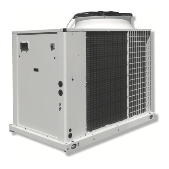
8 - Product Description Evaporators 8.1 General Information Evaporators are made of stainless steel plates. They are thermally SyScroll Air CO/HP units are one-block type with one refrigerant insulated by means of a thick flexible insulating mattress with closed circuit. They are intended to cool down the water required for any cells. -
Page 32: Product Description
8 - Product Description 8.2 Accessories Water Filter - with 1 pump that guarantee 150 kPa of available static pressure; It is assembled on the unit as a standard. - with 2 pumps that guarantee 150 kPa of available static pressure Water buffer tank Anti-Vibration Kit The hydro module is available for the units with a pump;... - Page 33 8 - Product Description Gauges kit Gauges kit is available as accessory. It is shipped loose and it’s not possible to have it factory mounted. Fan speed control Fan speed control is available as accessory to allow the chiller to operate down to external air temperature.
- Page 34 8 - Product Description 8.3 Refrigerant flow diagram - SyScroll Air CO 40 to 75 - R410A OIL EQUAL. INLET OUTLET SyScroll Air CO R410A (Fluid group 2): COMPONENTS VESSEL CATEGORY ( 2)/EVALUATION MODULE 1 Compressor tandem scroll type 2 / mod. D1 2 Air cooled condenser 3 Filter drier 4 Sight glass...
- Page 35 8 - Product Description Refrigerant flow diagram - SyScroll Air HP 40 to 75 - R410A OIL EQUAL. INLET OUTLET SyScroll Air HP R410A (Fluid group 2): COMPONENTS VESSEL CATEGORY ( 2)/EVALUATION MODULE 1 Compressor tandem scroll type 2 / mod. D1 2 4-way valve 3 Air cooled condenser 4 Biflow filter drier...
-
Page 36: Refrigeration Circuits
8 - Product Description Refrigerant flow diagram - SyScroll Air RE 40 to 75 - R410A INLET OIL EQUAL. OUTLET SyScroll Air RE R410A (Fluid group 2): COMPONENTS VESSEL CATEGORY ( 2)/EVALUATION MODULE 1 Compressor tandem scroll type 2 / mod. D1 2 Air cooled condenser SAFETY / CONTROL DEVICES HAZARD CATEGORY / EVALUATION MODULE... -
Page 37: Technical Data
9 - Technical Data Hydraulic features Evaporator water pressure drop 40-45 60-75 3000 4000 5000 6000 7000 8000 9000 10000 11000 12000 13000 14000 15000 16000 17000 18000 Water flow (l/h) Desuperheater water pressure drop 40-45 50-60 65-75 1000 1500 2000 2500 3000... - Page 38 9 - Technical Data Optional pump available static pressure 60-75 40-45 5500 6000 6500 7000 7500 8000 8500 9000 9500 1000 10500 11000 11500 12000 12500 13000 13500 14000 14500 15000 15500 16000 16500 17000 17500 Water flow (l/h) Note: The curves are referred to 2P+T unit.
- Page 39 9 - Technical Data 9.2 Physical data SyScroll Air CO 40 to 75 - BLN Version SyScroll AIR CO BLN Power supply V/ph/Hz 400V/3/50Hz Number of refrigerant circuits Total capacity steps 0-50-100 0-50-100 0-50-100 0-44-56-100 0-50-100 0-50-100 REFRIGERANT Type R410A Charge (1) 10.7 11.9...
- Page 40 9 - Technical Data SyScroll Air CO 40 to 75 - SLN Version SyScroll AIR CO SLN Power supply V/ph/Hz 400V/3/50Hz Number of refrigerant circuits Total capacity steps % 0-50-100 0-50-100 0-50-100 0-44-56-100 0-50-100 0-50-100 REFRIGERANT Type R410A Charge (1) 10.7 11.9 14.3...
- Page 41 9 - Technical Data SyScroll Air CO 40 to 75 - HT/HPF Version SyScroll Air CO HT/HPF Power supply V/ph/Hz 400V/3/50Hz Number of refrigerant circuits Total capacity steps % 0-50-100 0-50-100 0-50-100 0-44-56-100 0-50-100 0-50-100 REFRIGERANT Type R410A Charge (1) 10.7 11.9 14.3...
- Page 42 9 - Technical Data SyScroll Air HP 40 to 75 - BLN Version SyScroll Air HP BLN Power supply V/ph/Hz 400V/3/50Hz Number of refrigerant circuits Total capacity steps % 0-50-100 0-50-100 0-50-100 0-44-56-100 0-50-100 0-50-100 REFRIGERANT Type R410A Charge (1) 10.7 11.9 14.3...
- Page 43 9 - Technical Data SyScroll Air HP 40 to 75 - SLN Version SyScroll Air HP SLN Power supply V/ph/Hz 400V/3/50Hz Number of refrigerant circuits Total capacity steps % 0-50-100 0-50-100 0-50-100 0-44-56-100 0-50-100 0-50-100 REFRIGERANT Type R410A Charge (1) 10.7 11.9 14.3...
- Page 44 9 - Technical Data SyScroll Air HP 40 to 75 - HT/HPF Version SyScroll Air HP HT/HPF Power supply V/ph/Hz 400V/3/50Hz Number of refrigerant circuits Total capacity steps % 0-50-100 0-50-100 0-50-100 0-44-56-100 0-50-100 0-50-100 REFRIGERANT Type R410A Charge (1) 10.7 11.9 14.3...
- Page 45 9 - Technical Data SyScroll Air RE 40 to 75 - BLN Version SyScroll Air RE BLN Power supply V/ph/Hz 400V/3/50Hz Number of refrigerant circuits Total capacity steps % 0-50-100 0-50-100 0-50-100 0-44-56-100 0-50-100 0-50-100 REFRIGERANT Type R410A COMPRESSOR Type Scroll Number Start-up type...
- Page 46 9 - Technical Data SyScroll Air RE 40 to 75 - SLN Version SyScroll Air RE SLN Power supply V/ph/Hz 400V/3/50Hz Number of refrigerant circuits Total capacity steps % 0-50-100 0-50-100 0-50-100 0-44-56-100 0-50-100 0-50-100 REFRIGERANT Type R410A COMPRESSOR Type Scroll Number Start-up type...
- Page 47 9 - Technical Data SyScroll Air RE 40 to 75 - HT/HPF Version SyScroll Air RE HT/HPF Power supply V/ph/Hz 400V/3/50Hz Number of refrigerant circuits Total capacity steps % 0-50-100 0-50-100 0-50-100 0-44-56-100 0-50-100 0-50-100 REFRIGERANT Type R410A COMPRESSOR Type Scroll Number Start-up type...
-
Page 48: Physical Data
9 - Technical Data SyScroll Air RE Refrigerant Lines Unit connections Suction line dimensions [inch] Liquid line dimensions [inch] SyScroll Air RE Unit Suction Liquid Total equivalent lenght [m] Total equivalent lenght [m] [inch] [inch] 5/8” 1”3/8 1”3/8 1”3/8 1”3/8 7/8”... -
Page 49: Electrical Data
9 - Technical Data 9.3 Electrical data SyScroll Air CO/HP/RE BLN without pump Rated voltage V/ph/Hz 400V/3/50Hz Max. absorbed power with pump Max. current FLA Max. start-up current LRA External fuses Max. cable section (*) EXCHANGER RESISTANCE Rated voltage V/ph/Hz 230/1/50 Max. -
Page 50: Electrical Data
9 - Technical Data Compressor electrical data SyScroll Air CO/HP/RE BLN-SLN-HT/HPF Number Max. absorbed power 9.1+9.1 10.2+10.2 12+12 14.8+12 14.8+14.8 17.1+17.1 Rated current 95+95 111+111 118+118 140+118 140+140 173+173 Max current 16+16 21+21 22+22 31+22 31+31 40+40 Oil pan resistor 90+90 90+90 90+90... -
Page 51: Position Of Shock Adsorbers And Weight Distribution On Supports
9 - Technical Data 9.4 Position of shock absorbers and weight distribution on supports P1 - P4 Unit positions SyScroll Air CO SyScroll Air HP SyScroll Air RE P1-P4 P1-P4 P1-P4 Weight distribution Weight distribution Weight distribution Coordinates* Coordinates* Coordinates* (kg) (kg) (kg) - Page 52 9 - Technical Data 9.5 Dimensional Drawings - Units SyScroll Air CO/HP 40-50 Bottom view 4 x Ø10 Front view 1527 1000 4 x Ø22 Side view Top view 1527 1750 Dimensions in mm. Water inlet Ø2” gas male High pressure tap Desuperheater water inlet Ø1”...
- Page 53 9 - Technical Data Dimensional Drawings - Units SyScroll Air CO/HP 60-75 Bottom view 4 x Ø10 1977 Front view 1000 4 x Ø22 Side view Top view 1977 2200 Dimensions in mm. Water inlet Ø2" gas male High pressure tap Desuperheater water inlet Ø1"...
- Page 54 9 - Technical Data Dimensional Drawings - Units SyScroll Air RE 40 to 50 - R410A Bottom view 4 x Ø10 Front view 1527 1000 4 x Ø22 Side view Top view 1527 1750 Dimensions in mm. Electrical auxiliary lines Only for HT/HPF fan model Electrical power supply P1, P2, P3, P4...
-
Page 55: Dimensional Drawings
9 - Technical Data Dimensional Drawings - Units SyScroll Air RE 60 to 75 - R410A Bottom view 4 x Ø10 1977 Front view 1000 4 x Ø22 Side view Top view 1977 2200 Dimensions in mm. Electrical auxiliary lines Only for HT/HPF fan model Electrical power supply P1, P2, P3, P4... -
Page 56: Space Requirements
9 - Technical Data 9.6 Space Requirements Units SyScroll Air CO/HP/RE 40 to 75 3000 mm 1000 mm 1000 mm 1000 mm 1000 mm... -
Page 57: Maintenance
10 - Maintenance Carefully read the “Safety” section of this manual before carrying out any maintenance operations. Operations Do not discharge the refrigerant into the atmosphere while the refrigeration circuits Check the temperature are being drained. Use appropriate recovery of the leaving fluid equipment. -
Page 58: Refrigerant Charge
10 - Maintenance 10.3 Refrigerant charge 10.5 Condenser The condenser’s coils consist of copper pipes and aluminium fins. Do not inject refrigerant liquid into the LP side In the presence of leaks caused by any damage or shock, the coils of the circuit. -
Page 59: Sight Glass
10 - Maintenance 10.8 Sight glass Overheating calculation (S): S = Tse - Tsa The sight glass is used for inspecting the refrigerant flow and the humidity % of the refrigerant. The presence of bubbles indicates that Overheating is regulated through the thermostatic expansion valve. the dehydrating filter is clogged or the charge insufficient. -
Page 60: Troubleshooting
11 - Troubleshooting The table below lists the anomalies of operation of the unit, the relevant causes and the corrective measures. For anomalies of any other type or not listed, contact one of authorised Service Centre for technical assistance. Anomaly Cause Operation The unit continues... -
Page 61: Spare Parts
12 - Spare Parts 12.1 Spare part list The table below shows the list of spare parts recommended during the first two years of operation. Component Number High pressure switch Differential water pressure switch High pressure transducer Low pressure transducer Expansion valve Gas filter Four-way valve... -
Page 62: Dismantling, Demolition And Scrapping
13 - Dismantling, Demolition and Scrapping After draining operations, the piping of the hydraulic networks can be disconnected and disassembled. During the draining of the refrigeration circuits, do not let the refrigerant overflow in Once they have been disconnected as specified, the packaged units the surrounding atmosphere. - Page 63 ITALY COSTRUTTORE / MANUFACTURE - BUONE NORME DI MANUTENZIONE DEI DISPOSITIVI DI SICUREZZA MONTATI SUL GRUPPO FRIGORIFERO Gentile Cliente, Le ricordiamo alcune indicazioni circa le modalità di manutenzione dei dispositivi di sicurezza montati sul gruppo frigorifero da Lei acquistato. I dispositivi di sicurezza montati sul gruppo sono stati verificati dal COSTRUTTORE a norma di legge. È...
- Page 64 As part of our ongoing product improvement programme, our products are subject to change without prior notice. Non contractual photos. Dans un souci d’amélioration constante, nos produits peuvent être modifiés sans préavis. Photos non contractuelles. In dem Bemühen um ständige Verbesserung können unsere Erzeugnisse ohne vorherige Ankündigung geändert werden.
Need help?
Do you have a question about the SYSCROLL AIR CO/HP 40-75 and is the answer not in the manual?
Questions and answers