
Subscribe to Our Youtube Channel
Related Manuals for SystemAir SysAqua140


Summary of Contents for SystemAir SysAqua140
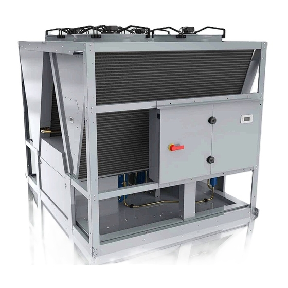
- Page 1 Installation and maintenance manual SysAqua 140 / 150 / 170 / 190 / 210 Air Cooled Water Chillers and Heat Pumps 143.7 â 217.6kW 125.4 â 208.8kW...
- Page 3 SysAqua INSTALLATION INSTRUCTION English NOTICE D’INSTALLATION Français INSTALLATIONSHANDBUCH Deutsch ISTRUZIONI INSTALLAZIONE Italiano INSTRUCCIONES DE INSTALACIÓN Español...
-
Page 4: Table Of Contents
2 SysAqua CONTENTS 1. GENERAL RECOMMENDATIONS ................................ 3 1.1. SAFETY DIRECTIONS ............................................3 1.2. WARNING ................................................. 3 1.3. EQUIPMENT SAFETY DATA ..........................................4 2. INSPECTION AND STORAGE ................................5 3. WARRANTY ...................................... 5 4. PRESENTATION ....................................5 5. CONTENTS OF PACKAGE ................................... 6 5.1. -
Page 5: General Recommendations
SysAqua POWER SUPPLY MUST BE SWITCHED OFF BEFORE STARTING WORK IN THE ELECTRIC CONTROL BOX 1. GENERAL RECOMMENDATIONS The purpose of this Manual is to provide users with instructions for installing, commissioning, using and maintaining the units. It also contains instructions on starting up the machine as well as recommendations to avoid bodily injury and risks of damage to the device during its operation. -
Page 6: Equipment Safety Data
4 SysAqua 1.3. EQUIPMENT SAFETY DATA Safety Data R410A Toxicity Skin contact with the rapidly evaporating liquid may cause tissue chilblains. In case of skin contact with In contact with skin the liquid, warm the frozen tissue with water and call a doctor. Remove contaminated clothing and footwear. -
Page 7: Inspection And Storage
SysAqua 2. INSPECTION AND STORAGE At the time of receiving the equipment carefully cross check all the elements against the shipping documents in order to ensure that all the crates and boxes have been received. Inspect all the units for any visible or hidden damage. -
Page 8: Contents Of Package
On opening the carton, check that all the accessories required for installation are present. 6. DIMENSIONS SEE APPENDIX 7. HANDLING 7.1. NET WEIGHT SysAqua140 SysAqua150 SysAqua170 SysAqua190 SysAqua210 Cooling only - Without pump 1 422 1 425 1 515 1 584... -
Page 9: Manutention Generalites
SysAqua 7.3. MANUTENTION GENERALITES The method of handling depends on the model of SysAqua and its final destination. Take care to avoid any rough handling or impacts when unloading and moving the appliance. ² Before hoisting into position, test lift to insure stability and balance. Avoid twisting or uneven lifting ²... -
Page 10: Handling By Slinging
8 SysAqua 7.3.2. HANDLING BY SLINGING Lifting is also possible by slinging. A spreader must be used to prevent damage to the machine edges. Caution Slings must never touch the unit casing of SysAqua. WITHOUT BUFFER TANK WITH BUFFER TANK... -
Page 11: Technical Specifications
SysAqua 8. TECHNICAL SPECIFICATIONS 8.1. PHYSICAL CHARACTERISTICS SysAqua140 SysAqua150 SysAqua170 SysAqua190 SysAqua210 Supply voltage 400V / 3~ N / 50Hz Number of refrigerang circuit REFRIGERANT Type R410A Factory charge SEE NAME PLATE COMPRESSORS Type Scroll Number Startup type DIRECT 0/24/26/48/50... -
Page 12: Refrigeration Specifications
10 SysAqua 8.2. REFRIGERATION SPECIFICATIONS 8.2.1. REFRIGERANT CIRCUIT DIAGRAM SEE APPENDIX 8.2.2. REFRIGERANT CHARGE Caution This equipment contains fluorinated gas with greenhouse gas effects covered by the Kyoto agreement. The type and quantity of refrigerating fluid per circuit are indicated on the product plate. The installer and end user will get informed on local environmental regulations for the installation, operation and disposal of the equipment ;... -
Page 13: Electric Specifications
SysAqua 8.3. ELECTRIC SPECIFICATIONS SysAqua140 SysAqua150 SysAqua170 SysAqua190 SysAqua210 Power supply 400 V / 3~ N / 50 Hz Maximum current Fuse rating aM Without Total starting current pump (without Soft starter) Total starting current (with Soft starter) Maximum current... -
Page 14: Installation
12 SysAqua 9. INSTALLATION Caution The unit is not designed to withstand weights or stresses from adjacent equipment, pipe work or constructions. Any foreign weight or stress on the unit structure could lead to a malfunction or a degradation with dangerous consequences for personnel and property. In such an event, the warranty shall be null and void. -
Page 15: Clearance
SysAqua 9.2. CLEARANCE When choosing the location for the SysAqua, take care to leave sufficient free clearance on 5 000 all sides to ensure easy access for maintenance 1 500 1 500 work. 1 500 WITH BUFFER TANK 1 500 5 000 2 000 1 500... -
Page 16: Hydraulic Links
14 SysAqua 10. HYDRAULIC LINKS Caution When choosing and installing water pipes, you must consult and observe all current local standards, regulations and instructions. 10.1. MAIN HYDRAULIC CIRCUIT Caution The mains hydraulic circuit will provide a constant water flow on the refrigerating fluid/water plate exchanger and in case of load variation. -
Page 17: Minimum Water Volume Requirements
Internal water tank : SysAqua 140-150-170-190-210 300L ² 10.3.1. SYSAQUA COOLING ONLY VERSION SysAqua140 SysAqua150 SysAqua170 SysAqua190 SysAqua210 Minimum water volume in the system application air conditioning Minimum water volume in the system 1 340 1 470 1 612... -
Page 18: Frost Protection
16 SysAqua 10.6. FROST PROTECTION 10.6.1. WATER LOOP GLYCOLING Caution THE USE OF A GLYCOL-BASED SOLUTION IS THE ONLY EFFECTIVE FROST-PROTECTION MEANS The glycol-based water solution must be sufficiently concentrated to ensure appropriate protection and prevent ice from forming. Take precautions when using non inert MEG antifreeze solutions (Mono Ethylene Glycol) or MPG (Mono Propylene Glycol). -
Page 19: Leaving Water Protection
SysAqua 10.6.3. LEAVING WATER PROTECTION In case of low temperature setpoint or reduced water flow, the water loop must be protected against icing during the operation of the unit. Concentration must comply with the minimum water temperature of the installation. The choice of the type of glycol shall take in consideration the increase of pressure drops. For instance, we recommend to protect a -10°C setpoint down to -18°C. -
Page 20: Heat Insulation
18 SysAqua 10.8. HEAT INSULATION To guarantee proper energy efficiency and compliance with current standards, water pipes passing through uninhabited zones should be properly lagged to retain heat. To achieve correct insulation with conductivity of 0.04 W/mK, lag the pipes with insulating material with a radial thickness between 25mm and 30 mm. -
Page 21: Wiring Diagram And Legend
230V 50Hz +/- 10% SE4598 models SysAqua140 to SysAqua210 circuit 2 Control 230V 50Hz +/- 10% SE4605 models SysAqua140 to SysAqua210 TTS circuit 1 Power 400 V / 3~ N / 50 Hz +/- 10% SE4606 models SysAqua140 to SysAqua210 TTS circuit 2... -
Page 22: Range And Settings Of Themal Protection / Nominal Intensity Of The Contactors (Classe Ac3)
20 SysAqua 11.2.3. RANGE AND SETTINGS OF THEMAL PROTECTION / NOMINAL INTENSITY OF THE CONTACTORS (CLASSE AC3) MODELS SysAqua140 SysAqua150 SysAqua170 SysAqua190 SysAqua210 Range 24-32A 23-32A 30-40A 30-40A 37-50A Adjustment Range 20-25A 23-32A 23-32A 30-40A 30-40A Adjustment Range 24-32A 23-32A... -
Page 23: Electrical Connections
SysAqua 12. ELECTRICAL CONNECTIONS WARNING Before carrying out any work on the equipment, make sure that the electrical power supply is disconnected and that there is no possibility unit being started inadvertently. Non-compliance with the above instructions can lead to injury or death by electrocution. The electrical installation must be performed by a fully qualified electrician, and in accordance with local electrical standards and the wiring diagram corresponding to the unit model. - Page 24 22 SysAqua Caution Supplying the unit with a line with an unbalance exceeding the acceptable value results in cancelling the warranty. Caution Correction of the excessive centralized power factor (>0.95) may generate transient phenomena dangerous for the motors and contactors of the unit during the start and stop phases. Check instant voltages during these phases.
-
Page 25: Regulation
SysAqua 13. REGULATION SysAqua units are fitted with an electronic control system. It provides the command, control and alarm functions. 13.1. ORDER OF PRIORITY FOR CONTROL SYSTEMS The integrated regulator in the SysAqua can be controlled by various interfaces and systems. The order of priority for each drive system is as follows: Timing programming: this scheduling is integrated in the regulator The BMS : the remote supervision transmits it commands according to the communication protocols... -
Page 26: Home Page
24 SysAqua 13.2.2. HOME PAGE The home page is used to quickly display the state of the machine by Main overview displaying the following information: Current mode Red. H Operating mode ² Entering water T. 42.3°C Water return temperature ² Leaving water T. -
Page 27: Initial Settings
SysAqua 13.3. INITIAL SETTINGS Open the electrical box and check that all circuit breakers are open except for FTC. Before starting up the SysAqua for the first time, the "Installation" menu must be configured. 13.3.1. TIME SETTINGS Caution If the date and time are not set, the unit will function in degraded mode or may not even be able to start. -
Page 28: Defining The Glycol Rate
26 SysAqua 13.3.3. DEFINING THE GLYCOL RATE Define the type and glycol content present in the installation water circuit. Main Menu Main Menu Status Status Commissioning Commissioning Commissioning Commissioning 1/12 1/12 03.02.2016 03.02.2016 10:40:05 10:40:05 Services Services Language selection Language selection Communications Communications Access... -
Page 29: Configuring Input D2
SysAqua 13.4.2. CONFIGURING INPUT D2 During installation, a switch can be connected onto the D2 digital input. The operating mode defined for this input takes priority over all control systems such as the HML, BMS or calendar. SD/N Main Menu Main Menu Status Status... -
Page 30: Selecting The Operating Mode
28 SysAqua 13.4.4. SELECTING THE OPERATING MODE To launch the unit, the user must select the desired mode in the menu: ² Delegate : the current mode is Main Menu Main Menu Status Status 1/13 1/13 Status Status determined by the BMS or by HMI state HMI state Delegate... -
Page 31: Water Law
SysAqua 13.4.6. WATER LAW The configuration of the different water law settings dynamically matches the setpoint according to the outside temperature. The different parameters below for the water law can be set in the installation menu and by a GTC. Main Menu Main Menu Status... - Page 32 30 SysAqua 13.4.6.2. HEAT MODE The water law replaces the heat mode setpoint with the f function of the OAT outside temperature: water law setpoint = f(OAT) ² Function f is restricted between 20 and 50°C. It is defined by points A, B and C in the graph below. The values indicated are factory values.
-
Page 33: Variable Primary Flow" Option
SysAqua 13.4.7. "VARIABLE PRIMARY FLOW” OPTION Main Menu Main Menu Status Status Commissioning Commissioning Services Services Service Service Configuration Configuration Configuration Configuration Access Access Manual control Manual control Deice Deice Pump Pump Pump configuration 1/13 Operation hours Operation hours Circuit control Circuit control Lock out Lock out... - Page 34 32 SysAqua 13.4.7.2. CONSTANT SPEED MODE VS CAPACITY The speed of the pump depends on the capacity of the unit. This speed range is determined during commissioning to adjust the power of the pump to the load drops of the installation. Speed set-point 100% Pump configuration...
-
Page 35: Reduced Mode
SysAqua Set all units in demand to open all the valves (load = 100%). Pump configuration Pump configuration 1/15 1/15 Pump Pump Single Single Set the water pressure setting to a high value (example: 8.0 bar) Continuous pump Continuous pump Modulation Modulation 2 stages... -
Page 36: Alarms
34 SysAqua 13.5. ALARMS Main overview Trigger all circuit breakers. Silence the alarm. Current mode Red. H If at least one alarm or warning is in progress, the alarm button flashes. Entering water T. 42.3°C Press the 'Alarm' button to access the latest current alarm. The Leaving water T. -
Page 37: Schedule
SysAqua 13.6. SCHEDULE The first line displayed shows the current mode at the level of time programming. Main Menu Main Menu Status Status Commissioning Commissioning Commissioning Commissioning 1/12 1/12 03.02.2016 03.02.2016 10:40:05 10:40:05 Services Services Language selection Language selection Communications Communications Access Access... -
Page 38: Commissioning
36 SysAqua 14. COMMISSIONING Caution When performing startup and service, thorough safety precautions shall always be taken. Only qualified individuals should perform these functions. 14.1. PRE-START CHECK LIST Before commissioning the system, you must carry out a certain number of installation checks to ensure that the appliance will operate in the best possible conditions. -
Page 39: Operating Check List
SysAqua 14.2. OPERATING CHECK LIST 14.2.1. GENERAL Cheek for any unusual noises or vibration in the running components. 14.2.2. PHASE ROTATION PROTECTION If the phase of the power supply are not correct, the phase rotation protection device will prevent the machine from starting. -
Page 40: Final Check
38 SysAqua 14.2.5.1. PUMP MANAGEMENT The pump operates as long as the SysAqua is not in Off mode. For the double pump option, the pumps never operate simultaneously. The operating priority is given to the first pump motor. The second pump motor backs up the first in the event that it becomes faulty. The first pump motor will be stopped and replaced automatically by the second motor in the following situations:... -
Page 41: Maintenance
SysAqua 17. MAINTENANCE Caution The user is responsible for ensuring that the unit is in perfect working order and that the technical installation and minimum maintenance operations have been performed by a qualified technician in accordance with the procedures described in the present manual. Depending on actual operational constraints and regulatory changes, the installer might recommend increased maintenance operations and more frequent inspections. -
Page 42: Periodic Table Of Service And Maintenance
40 SysAqua 17.2. PERIODIC TABLE OF SERVICE AND MAINTENANCE month months months months months TASKS PER COMPONENTS ACTIONS Recommended inspection and maintenance interval 1 - Casing Control possible contaminations, damage Clean and repair if required. and/or corrosion. Check the possible presence of water Clean and look for the cause, then ... - Page 43 SysAqua month months months months months TASKS PER COMPONENTS ACTIONS Recommended inspection and maintenance interval 3.10 Check filter cleanliness. Clean Check that the hydraulic circuit is filled 3.11 properly Check the condition of the expansion 3.12 tank (presence of excess corrosion, or gas Replace if required.
-
Page 44: Maintenance Procedures
42 SysAqua 17.3. MAINTENANCE PROCEDURES 17.3.1. REFRIGERANT CIRCUIT This equipment must be submitted to sealing checks minimum once per year, by a professional authorized to perform such an operation. Refer to national requirements for the frequency of these checks. Caution Never use the compressor as a vacuum pump to drain the installation. -
Page 45: Hydraulic Circuit
SysAqua 17.3.1.4. AIR COOLED CONDENSER Caution Fin edges are sharp and can cause injury hazard. Avoid contact with them. Condenser coils are composed of copper tubes and aluminium fins. In case of leaks due to damage or shock, the coils must be repaired by one of the authorized Support Centres. To guarantee the best possible operation of the condenser bank, the condenser surface must be maintained as clean as possible, and it must be void of foreign materials (leaves, wires, insects, slag, etc.). -
Page 46: Trouble Shooting
44 SysAqua 18. TROUBLE SHOOTING Problem Probable cause Solution Insufficient refrigerant fluid charge. Top up the refrigerant fluid charge. Unit operates continuously but without Clogged dehumidification filter. Replace the dehumidification filter. generating cooling Reduced output from one or both circuits Check the compressor valves and change them if necessary. - Page 47 SysAqua Problem Probable cause Solution Presence of a leak. Identify and repair the leak. Circuit stoppage further to the low pressure Insufficient refrigerant fluid charge. Top up the refrigerant fluid charge. thermostat being activated. Pressostat operating fault. Replace the pressostat. Incorrect operation of the high pressure Check the operation of the pressostat.
- Page 48 46 SysAqua...
- Page 49 APPENDIX / ANNEXE / ANLAGE / ALLEGATO / ANEXO APPENDIX ANNEXE ANLAGE ALLEGATO ANEXO...
- Page 50 REFRIGERANT CIRCUIT DIAGRAM ............VIII POWER - CIRCUIT 1 ......................XXIV POWER - CIRCUIT 2 ......................XXV COOLING ONLY VERSION - SYSAQUA140.L TO SYSAQUA150.L ........IX CONTROL - CIRCUIT 1 ...................... XXVI COOLING ONLY VERSION - SYSAQUA170.L ..............IX CONTROL - CIRCUIT 2 ..................... XXVII COOLING ONLY VERSION - SYSAQUA190.L TO SYSAQUA210.L ........
- Page 51 APPENDIX / ANNEXE / ANLAGE / ALLEGATO / ANEXO DIMENSIONS DIMENSIONS ABMESSUNGEN DIMENSIONI DIMENSIONES SYSAQUA WITHOUT PUMP Ø17 1145 1249 1249 1145 2804 Ø2"1/2 1100 INTLET WATER OUTLET 2856 SysAqua...
- Page 52 APPENDIX / ANNEXE / ANLAGE / ALLEGATO / ANEXO SYSAQUA WITH 1 PUMP Ø17 1145 1249 1249 1145 2804 Ø2"1/2 1100 INTLET OUTLET 2856 WATER IV SysAqua...
- Page 53 APPENDIX / ANNEXE / ANLAGE / ALLEGATO / ANEXO SYSAQUA WITH 2 PUMPS Ø17 1145 1249 1249 1145 2804 Ø2"1/2 1100 INTLET 2856 OUTLET WATER SysAqua...
- Page 54 APPENDIX / ANNEXE / ANLAGE / ALLEGATO / ANEXO SYSAQUA WITH 1 PUMP AND BUFFER TANK Ø17 1145 1249 1249 1145 2804 Ø2"1/2 1740 INTLET OUTLET 3666 WATER VI SysAqua...
- Page 55 APPENDIX / ANNEXE / ANLAGE / ALLEGATO / ANEXO SYSAQUA WITH 2 PUMPS AND BUFFER TANK Ø17 1145 1249 1249 1145 2804 Ø2"1/2 1740 INTLET OUTLET 3666 WATER SysAqua...
- Page 56 APPENDIX / ANNEXE / ANLAGE / ALLEGATO / ANEXO REFRIGERANT CIRCUIT DIAGRAM SCHEMA DU CIRCUIT FRIGORIFIQUE KÄLTEKREISLAUFDIAGRAMM SCHEMA DEL CIRCUITO REFRIGERANTE ESQUEMA DEL CIRCUITO FRIGORIFÍCO English Français Deutsch M1-1 circuit 1 Compressors 1 M1-1 circuit 1 Compresseurs 1 M1-1 Kreislauf 1 Kompressor 1 M1-2 circuit 1...
- Page 57 APPENDIX / ANNEXE / ANLAGE / ALLEGATO / ANEXO COOLING ONLY VERSION - SYSAQUA140.L TO SYSAQUA150.L FPC1 CDT1 CDT2 FPC2 M2-1 M1-1 M1-2 M2-2 CST1 FPE1 FPE2 CST2 WATER OCT1 OCT2 COOLING ONLY VERSION - SYSAQUA170.L FPC1 CDT1 CDT2 FPC2...
- Page 58 APPENDIX / ANNEXE / ANLAGE / ALLEGATO / ANEXO HEAT PUMP VERSION - SYSAQUA140.H TO SYSAQUA150.H FPC1 CDT1 CDT2 FPC2 M2-1 M1-1 M1-2 M2-2 CST1 FPE1 FPE2 CST2 WATER OCT2 OCT1 HEAT PUMP VERSION - SYSAQUA170.H FPC1 CDT1 CDT2 FPC2...
- Page 59 APPENDIX / ANNEXE / ANLAGE / ALLEGATO / ANEXO HYDRAULIC CIRCUIT DIAGRAM SCHEMA DU CIRCUIT HYDRAULIQUE HYDRAULISCHER SCHALTPLAN SCHEMA CIRCUITALE IDRAULICO ESQUEMA CIRCULAR HIDRÁULICO Deutsch English Français RECOMMENDED INSTALLATION INSTALLATION RECOMMANDEE EMPFOHLENE INSTALLATION Connexion flexible Connexion flexible Schlauchverbindung Drain valve Vanne de vidange Ablassventil Globe valve...
- Page 60 APPENDIX / ANNEXE / ANLAGE / ALLEGATO / ANEXO WITHOUT PUMP WITH 1 PUMP WITH 2 PUMPS XII SysAqua...
- Page 61 APPENDIX / ANNEXE / ANLAGE / ALLEGATO / ANEXO PRESSURE LOSSES PERTE DE CHARGE DE L'ECHANGEUR A PLAQUES DRUCKVERLUST PERDITA DI CARICO PÉRDIDA DE CARGA 1000 SysAqua 140-150 SysAqua 170-190-210 7 8 9 60 70 80 90 Water flow SysAqua XIII...
- Page 62 APPENDIX / ANNEXE / ANLAGE / ALLEGATO / ANEXO HYDRAULIC PUMPS CURVES COURBES DES POMPES HYDRAULIQUES KURVEN VON HYDRAULIKPUMPEN CURVE DELLE POMPE IDRAULICHE CURVAS BOMBAS HIDRÁULICAS STANDARD PUMP SYSAQUA 140 - 150 - 170 50 Hz 45 Hz 40 Hz 35 Hz 30 Hz Water flow (m...
- Page 63 APPENDIX / ANNEXE / ANLAGE / ALLEGATO / ANEXO SYSAQUA 190 - 210 50 Hz 45 Hz 40 Hz 35 Hz 30 Hz Water flow (m 50 Hz 45 Hz 40 Hz 35 Hz 30 Hz Water flow (m SysAqua...
- Page 64 APPENDIX / ANNEXE / ANLAGE / ALLEGATO / ANEXO HIGHT PRESSURE PUMP SYSAQUA 140 - 150 - 170 - 190 50 Hz 45 Hz 40 Hz 35 Hz 30 Hz Water flow (m 50 Hz 45 Hz 40 Hz 35 Hz 30 Hz Water flow (m XVI SysAqua...
- Page 65 APPENDIX / ANNEXE / ANLAGE / ALLEGATO / ANEXO SYSAQUA 210 50 Hz 45 Hz 40 Hz 35 Hz 30 Hz Water flow (m 50 Hz 45 Hz 40 Hz 35 Hz 30 Hz Water flow (m SysAqua XVII...
- Page 66 APPENDIX / ANNEXE / ANLAGE / ALLEGATO / ANEXO WIRING DIAGRAM SCHEMAS ELECTRIQUES STROMLAUFPLANS SCHEMA ELETRICO ESQUEMA ELECTRICO TAKE CARE! These wiring diagrams are correct at the time of publication. Manufacturing changes can lead to modifications. Always refer to the diagram supplied with the product. ATTENTION Ces schémas sont corrects au moment de la publication.
- Page 67 APPENDIX / ANNEXE / ANLAGE / ALLEGATO / ANEXO LEGEND SysAqua...
- Page 68 APPENDIX / ANNEXE / ANLAGE / ALLEGATO / ANEXO XX SysAqua...
- Page 69 APPENDIX / ANNEXE / ANLAGE / ALLEGATO / ANEXO SysAqua...
- Page 70 APPENDIX / ANNEXE / ANLAGE / ALLEGATO / ANEXO XXII SysAqua...
- Page 71 APPENDIX / ANNEXE / ANLAGE / ALLEGATO / ANEXO SysAqua XXIII...
- Page 72 APPENDIX / ANNEXE / ANLAGE / ALLEGATO / ANEXO POWER - CIRCUIT 1 XXIV SysAqua...
- Page 73 APPENDIX / ANNEXE / ANLAGE / ALLEGATO / ANEXO POWER - CIRCUIT 2 SysAqua...
- Page 74 APPENDIX / ANNEXE / ANLAGE / ALLEGATO / ANEXO CONTROL - CIRCUIT 1 XXVI SysAqua...
- Page 75 APPENDIX / ANNEXE / ANLAGE / ALLEGATO / ANEXO CONTROL - CIRCUIT 2 SysAqua XXVII...
- Page 76 APPENDIX / ANNEXE / ANLAGE / ALLEGATO / ANEXO POWER - CIRCUIT 1 TTS XXVIII SysAqua...
- Page 77 APPENDIX / ANNEXE / ANLAGE / ALLEGATO / ANEXO POWER - CIRCUIT 2 TTS SysAqua XXIX...
- Page 78 APPENDIX / ANNEXE / ANLAGE / ALLEGATO / ANEXO CONTROL - CIRCUIT 1 TTS XXX SysAqua...
- Page 79 APPENDIX / ANNEXE / ANLAGE / ALLEGATO / ANEXO CONTROL - CIRCUIT 2 TTS SysAqua XXXI...
- Page 80 APPENDIX / ANNEXE / ANLAGE / ALLEGATO / ANEXO POWER - CIRCUIT 1 - WITHOUT NEUTRAL XXXII SysAqua...
- Page 81 APPENDIX / ANNEXE / ANLAGE / ALLEGATO / ANEXO POWER - CIRCUIT 2 - WITHOUT NEUTRAL SysAqua XXXIII...
- Page 82 APPENDIX / ANNEXE / ANLAGE / ALLEGATO / ANEXO CONTROL - CIRCUIT 1 - WITHOUT NEUTRAL XXXIV SysAqua...
- Page 83 APPENDIX / ANNEXE / ANLAGE / ALLEGATO / ANEXO CONTROL - CIRCUIT 2 - WITHOUT NEUTRAL SysAqua XXXV...
- Page 84 APPENDIX / ANNEXE / ANLAGE / ALLEGATO / ANEXO POWER - CIRCUIT 1 TTS - WITHOUT NEUTRAL XXXVI SysAqua...
- Page 85 APPENDIX / ANNEXE / ANLAGE / ALLEGATO / ANEXO POWER - CIRCUIT 2 TTS - WITHOUT NEUTRAL SysAqua XXXVII...
- Page 86 APPENDIX / ANNEXE / ANLAGE / ALLEGATO / ANEXO CONTROL - CIRCUIT 1 TTS - WITHOUT NEUTRAL XXXVIII SysAqua...
- Page 87 APPENDIX / ANNEXE / ANLAGE / ALLEGATO / ANEXO CONTROL - CIRCUIT 2 TTS - WITHOUT NEUTRAL SysAqua XXXIX...
- Page 88 APPENDIX / ANNEXE / ANLAGE / ALLEGATO / ANEXO XL SysAqua...
- Page 89 APPENDIX / ANNEXE / ANLAGE / ALLEGATO / ANEXO START UP FORM / FICHE DE MISE EN SERVICE CUSTOMER INFORMATION: Order number: ..............Job name: ................. Contractor: ................Installation address: ............................... Contact: ................: ................... INSTALLER INFORMATION: Company: ................Address: ...................................
- Page 90 APPENDIX / ANNEXE / ANLAGE / ALLEGATO / ANEXO INSTALLATION MEASUREMENTS: Ambient temperature: ............Ambient humidity: ................................. ELECTRICAL MEASUREMENTS: Voltage L1-N: ..............Voltage L1-L2:: ............... Voltage L1-L3: ..............Voltage L2-L3:: ................................Never start the unit if the voltage unbalance is over 2 %.
- Page 92 As part of our ongoing product improvement programme, our products are subject to change without prior notice. Non contractual photos. Systemair AC SAS Route de Verneuil 27570 Tillières-sur-Avre FRANCE & : +33 (0)2 32 60 61 00 6 : +33 (0)2 32 32 55 13...
Need help?
Do you have a question about the SysAqua140 and is the answer not in the manual?
Questions and answers