
Related Manuals for SystemAir SYSAQUA BLUE.L 35B


Summary of Contents for SystemAir SYSAQUA BLUE.L 35B
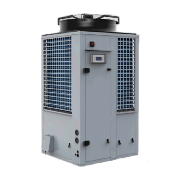
- Page 1 Installation and maintenance manual SYSAQUA BLUE Air Cooled Water Chillers and Heat Pumps 35.4kW 31.7kW...
- Page 3 INSTALLATION INSTRUCTION English NOTICE D’INSTALLATION Français INSTALLATIONSHANDBUCH Deutsch ISTRUZIONI INSTALLAZIONE Italiano INSTRUCCIONES DE INSTALACIÓN Español...
-
Page 4: Table Of Contents
2 SYSAQUA BLUE CONTENTS 1. GENERAL RECOMMENDATIONS ................................ 3 1.1. SAFETY DIRECTIONS ....................................................3 1.2. WARNING ........................................................3 1.3. EQUIPMENT SAFETY DATA ..................................................4 2. INSPECTION AND STORAGE ................................5 3. WARRANTY ...................................... 5 4. PRESENTATION ....................................5 5. CONTENTS OF PACKAGE ................................... 6 5.1. -
Page 5: General Recommendations
SYSAQUA BLUE POWER SUPPLY MUST BE SWITCHED OFF BEFORE STARTING WORK IN THE ELECTRIC CONTROL 1. GENERAL RECOMMENDATIONS The purpose of this Manual is to provide users with instructions for installing, commissioning, using and maintaining the units. It also contains instructions on starting up the machine as well as recommendations to avoid bodily injury and risks of damage to the device during its operation. -
Page 6: Equipment Safety Data
4 SYSAQUA BLUE 1.3. EQUIPMENT SAFETY DATA Safety data R290 Toxicity level Acute toxicity If the fluid comes into contact with your skin: treat the freeze burns as you would a normal burn. Immediately remove all contaminated clothing In contact with the skin and footwear Rinse the affected area immediately with plenty of water If you burn your skin, call a doctor without delay. -
Page 7: Inspection And Storage
SYSAQUA BLUE 2. INSPECTION AND STORAGE Upon receipt of the equipment, carefully cross check all the elements against the shipping documents to ensure that all expected crates and boxes have been delivered. Inspect all the units for any visible or hidden damage. -
Page 8: Contents Of Package
6 SYSAQUA BLUE 5. CONTENTS OF PACKAGE SYSAQUA BLUE Water filter Bag with the documentation 5.1. OPTIONAL ACCESSORIES Anti-vibration rubber pads Spring pads Isolating valve On opening the box, check that all of the accessories required for installation are present. 6. -
Page 9: Handling With A Forklift
SYSAQUA BLUE Caution When handling the SYSAQUA BLUE, beware not to damage the finned battery pack. Protect it with cardboard or particle panels. 7.3.1. HANDLING WITH A FORKLIFT A forklift can be used to handle the SYSAQUA BLUE units when palletized. Place a safety wedge between the unit base and the fork lift truck to avoid damaging the unit’s structure and casing. -
Page 10: Technical Specifications
8 SYSAQUA BLUE 8. TECHNICAL SPECIFICATIONS 8.1. PHYSICAL CHARACTERISTICS Supply voltage 400V / 3~ N / 50Hz Number of refrigeration circuits REFRIGERANT Type R290 Factory charge SEE NAME PLATE COMPRESSORS Type Scroll Number Startup type DIRECT Part load steps 0/50/100 Crankcase heater 2x53 EVAPORATOR... -
Page 11: Refrigeration Specifications
SYSAQUA BLUE 8.2. REFRIGERATION SPECIFICATIONS 8.2.1. REFRIGERANT CIRCUIT DIAGRAM SEE APPENDIX 8.2.2. REFRIGERANT CHARGE Caution This equipment contains a hydrocarbon (R290) that belongs to fluid category I as per standard EN378‑1. Unlike fluorocarbon fluids, this gas presents no risk to the environment (low GWP, fluid not covered by the Kyoto Protocol). -
Page 12: Operating Limits
10 SYSAQUA BLUE 8.4. OPERATING LIMITS 8.4.1. SYSAQUA BLUE.L/SYSAQUA BLUE.H COOLING MODE BRINES or WATER WATER + GLYCOL BRINES or WATER + GLYCOL WATER + Fan speed controller + Fan speed controller Leaving water temperature (°C) 8.4.2. SYSAQUA BLUE.H HEATING MODE Leaving water temperature (°C) -
Page 13: Installation
SYSAQUA BLUE 9. INSTALLATION Caution The unit is not designed to withstand weights or stresses from adjacent equipment, pipe work or constructions. Any foreign weight or stress on the unit structure could lead to a malfunction or damage, which could prove hazardous to personnel and property. In such an event, the warranty shall be voided. -
Page 14: Clearance
12 SYSAQUA BLUE 9.2. CLEARANCE During installation, it is important to leave sufficient 3 000 clearance around the SYSAQUA BLUE. 2 000 2 000 3 000 2 000 2 000 The unit is equipped with a R290 refrigerant leak detection card enabling it to be shut down and for 2 000 2 000 the hydrocarbon to be expelled into the atmosphere... -
Page 15: Hydraulic Links
SYSAQUA BLUE 10. HYDRAULIC LINKS Caution When choosing and installing water pipes, you must consult and observe all current local standards, regulations and instructions. 10.1. MAIN HYDRAULIC CIRCUIT Caution The mains hydraulic circuit will provide a constant water flow on the refrigerating fluid/water plate exchanger and in case of load variation. -
Page 16: Minimum Water Volume Requirements
14 SYSAQUA BLUE 10.3. MINIMUM WATER VOLUME REQUIREMENTS To ensure that the system operates correctly you must use suitably sized and properly routed pipes for the hydraulic links between the SYSAQUA BLUE and the mains network. Proper operation of the regulation and safety devices is ensured only when the water volume is sufficient. -
Page 17: Frost Protection
SYSAQUA BLUE 10.6. FROST PROTECTION If the SYSAQUA BLUE is exposed to ambient temperatures between 1°C and -18°C, protect the water circuit against frost. Caution THE USE OF A GLYCOL-BASED SOLUTION IS THE ONLY EFFECTIVE FROST-PROTECTION MEANS The glycol‑based water solution must be sufficiently concentrated to ensure appropriate protection and prevent ice from forming at the minimum outdoor temperatures planned for the installation. -
Page 18: Water Quality
16 SYSAQUA BLUE 10.7. WATER QUALITY The water must be analyzed; the hydraulic network system installed must include all elements necessary for water treatment: filters, additives, intermediate exchangers, drain valves, vents, check valves, etc., according to the results of the analysis. Caution The SYSAQUA BLUE must not run on a network with open loops, likely to cause incidents related to oxygenation, or with untreated ground water. -
Page 19: Heat Insulation
SYSAQUA BLUE 10.8. HEAT INSULATION To guarantee proper energy efficiency and compliance with current standards, water pipes passing through uninhabited zones should be properly lagged to retain heat. To achieve correct insulation with conductivity of 0.04 W/mK, lag the pipes with insulating material with a radial thickness between 25mm and 30 mm. -
Page 20: Wiring Diagram And Setting Range
18 SYSAQUA BLUE 11. WIRING DIAGRAM AND SETTING RANGE 11.1. WIRING DIAGRAM SEE APPENDIX SE4855 model 35B Control Mono 230V 50Hz +/- 10% SE4854 model 35B Power Tri 400V+N 50Hz +/- 10% SE4817 model 35B all seasons Control Mono 230V 50Hz +/- 10% SE4818 model 35B all seasons Power... -
Page 21: Electrical Connections
SYSAQUA BLUE 12. ELECTRICAL CONNECTIONS WARNING BEFORE CARRYING OUT ANY WORK ON THE EQUIPMENT, MAKE SURE THAT THE ELECTRICAL POWER SUPPLY IS DISCONNECTED AND THAT THERE IS NO POSSIBILITY OF THE UNIT BEING STARTED INADVERTENTLY. ALSO MAKE SURE THAT THE ALARM INDICATOR CABLES ARE DISCONNECTED. -
Page 22: Unit Power Supply
20 SYSAQUA BLUE Caution Supplying the unit with a line with an unbalance exceeding the acceptable value will void the warranty. Caution Correction of the excessive centralized power factor (>0.95) may generate transient phenomena dangerous for the unit motors and contactors during the start and stop phases. Check instant voltages during these phases. -
Page 23: Alarm Indicators
SYSAQUA BLUE 12.2. ALARM INDICATORS The SYSAQUA BLUE unit has two alarm indicators: general alarm indicator ² gas detection module alarm indicator ² 12.2.1. MAIN CONTROLLER The SYSAQUA BLUE control system has a dedicated alarm indicator. This information is available via a dry contact by connecting to the unit’s terminals 3 and 4. -
Page 24: Control
22 SYSAQUA BLUE 13. CONTROL SYSAQUA BLUE units are fitted with an electronic control system. It provides the command, control and alarm functions. 13.1. ORDER OF PRIORITY FOR CONTROL SYSTEMS The integrated regulator in the SYSAQUA BLUE can be controlled by various interfaces and systems. The order of priority for each drive system is as follows: Timing programming: this scheduling is integrated in the regulator The BMS: the remote supervision transmits it commands according to the communication protocols... -
Page 25: Home Page
SYSAQUA BLUE 13.2.2. HOME PAGE The home page is used to quickly display the state of the machine by Main overview displaying the following information: Current mode Red. H Operating mode ² Entering water T. 42.3°C Water return temperature ² Leaving water T. -
Page 26: Initial Settings
24 SYSAQUA BLUE 13.3. INITIAL SETTINGS Open the electrical box and check that all circuit breakers are open except for FTC. Before starting up the SYSAQUA BLUE for the first time, the "Installation" menu must be configured. 13.3.1. TIME SETTINGS Caution If the date and time are not set, the unit will function in degraded mode or may not even be able to start. -
Page 27: Defining The Glycol Rate
SYSAQUA BLUE 13.3.3. DEFINING THE GLYCOL RATE Define the type and glycol content present in the installation water circuit. Main Menu Main Menu Status Status Commissioning Commissioning Commissioning Commissioning 1/12 1/12 03.02.2016 03.02.2016 10:40:05 10:40:05 Services Services Language selection Language selection Communications Communications Access... -
Page 28: Configuring Input D2
26 SYSAQUA BLUE 13.4.2. CONFIGURING INPUT D2 During installation, a switch can be connected to the D2 digital input. The operating mode defined for this input takes priority over all control systems such as the HML, BMS or calendar. SD/N Main Menu Main Menu Status... -
Page 29: Selecting The Operating Mode
SYSAQUA BLUE 13.4.4. SELECTING THE OPERATING MODE To launch the unit, the user must select the desired mode in the menu: ² Delegate: the current mode is Main Menu Main Menu Status Status Status Status 1/12 1/12 determined by the BMS or by HMI state HMI state HMI state... -
Page 30: Water Law
28 SYSAQUA BLUE 13.4.6. WATER LAW The configuration of the different water law settings dynamically matches the setpoint according to the outside temperature. The different parameters below for the water law can be set in the installation menu and by a GTC. Main Menu Main Menu Status... - Page 31 SYSAQUA BLUE 13.4.6.2. HEAT MODE The water law replaces the heat mode setpoint with the f function of the OAT outside temperature: water law setpoint = f(OAT) ² Function f is restricted between 20 and 50°C. It is defined by points A, B and C in the graph below. The values indicated are factory values.
-
Page 32: Variable Primary Flow" Option
30 SYSAQUA BLUE 13.4.7. "VARIABLE PRIMARY FLOW” OPTION Main Menu Main Menu Status Status Commissioning Commissioning Services Services Service Service Configuration Configuration Configuration Configuration Access Access Manual control Manual control Deice Deice Pump Pump Pump configuration 1/13 Operation hours Operation hours Circuit control Circuit control Lock out... - Page 33 SYSAQUA BLUE 13.4.7.2. VC MODE - CONSTANT SPEED VS CAPACITY The speed of the pump depends on the capacity of the unit. This speed range is determined during commissioning to adjust the power of the pump to the load drops of the installation. Speed set-point 100% Pump configuration...
- Page 34 32 SYSAQUA BLUE It is necessary to determine the pressure setting to be maintained in the system then set the frequency inverter according to this pressure value. 13.4.7.3.1. DETERMINATION OF THE PRESSURE SETTING The frequency inverter ACS3 displays the reading via the pressure transducer WPT. Set all units in demand to open all the valves (load = 100%).
-
Page 35: Reduced Mode
SYSAQUA BLUE 13.4.8. REDUCED MODE Main Menu Main Menu Status Status Commissioning Commissioning Commissioning Commissioning 1/12 1/12 03.02.2016 03.02.2016 10:40:05 10:40:05 Services Services Language selection Language selection Communications Communications Access Access Glycol protection Glycol protection Auto change over Auto change over Water Law Water Law Reduced mode can have the following... -
Page 36: Alarms
34 SYSAQUA BLUE 13.5. ALARMS If no alarm is active, pressing the "Alarm" button takes you to the alarm history Main overview Alarm history - i compressor oil heating Current mode Red. H + Fault supp.pump: Alarm + Condensing P. Circuit 1:.. Entering water T. -
Page 37: Alarms History
SYSAQUA BLUE 13.5.3. ALARMS HISTORY This history reports the 50 most recent alarm activations and deactivations: Activation of an alarm will be indicated by a "+" ² Deactivation of an alarm will be indicated by a "-" ² Alarm history Alarm deactivated - i compressor oil heating Alarm 1 activated... -
Page 38: Commissioning
36 SYSAQUA BLUE 14. COMMISSIONING Caution When performing startup and service, thorough safety precautions shall always be taken. Only a skilled person who is trained in the handling of refrigerating systems (as per standard EN13313) and flammable fluids (certified and with proof of relevant training) may carry out this work. -
Page 39: Hydraulic Check
SYSAQUA BLUE 14.1.3. HYDRAULIC CHECK 1. Check that the external water circuit components (pumps, user equipment, filters, expansion tank and reservoir if supplied) have been correctly installed in accordance with the manufacturer’s recommendations and that the water inlet and outlet connections are correct. 2. -
Page 40: Hydraulic Circuit
38 SYSAQUA BLUE 14.3.4. HYDRAULIC CIRCUIT 1. Check the filter's cleanliness 2. Check the presence and position of the stop valves to isolate the unit during maintenance periods 3. Adjust the water flow to specifications. (see appended graphs). Check pressure at the inlet and outlet of the plate exchanger Determine the water flow using a flowmeter or the load loss of the plate exchanger 4. -
Page 41: Ordering Service And Spare Parts Order
SYSAQUA BLUE 16. ORDERING SERVICE AND SPARE PARTS ORDER The part number, the order confirmation and the unit serial number indicated on the name plate must be provided whenever services or spare parts are ordered. For any spare part order, indicate the date of unit installation and date of failure. Use the part number provided by our spare parts department. -
Page 42: Weekly Check
40 SYSAQUA BLUE 17.1. WEEKLY CHECK Inspect the entire running installation, while paying particular attention to: any damage on the SYSAQUA BLUE housing ² any traces of oil (sign of refrigerating fluid leak) ² any water leak ² the presence of removed protections, doors or lids improperly closed ²... -
Page 43: Table Of Periodic Service And Maintenance
SYSAQUA BLUE 17.2. TABLE OF PERIODIC SERVICE AND MAINTENANCE month months months months months TASKS PER COMPONENTS ACTIONS Recommended inspection and maintenance interval 1 - Casing Control possible contaminations, damage Clean and repair if required. and/or corrosion. Check the possible presence of water Clean and look for the cause, then ... - Page 44 42 SYSAQUA BLUE month months months months months TASKS PER COMPONENTS ACTIONS Recommended inspection and maintenance interval 3.10 Check filter cleanliness. Clean Check that the hydraulic circuit is filled 3.11 properly Check the condition of the expansion 3.12 tank (presence of excess corrosion, or gas Replace if required.
-
Page 45: Maintenance Procedures
SYSAQUA BLUE 17.3. MAINTENANCE PROCEDURES 17.3.1. REFRIGERANT CIRCUIT This equipment must be submitted for sealing checks at least once per year, by a professional authorized to perform such an operation. Refer to national requirements for the frequency of these checks. Caution Never use the compressor as a vacuum pump to drain the installation. -
Page 46: Hydraulic Circuit
44 SYSAQUA BLUE 17.3.1.4. AIR COOLED CONDENSER Caution Fin edges are sharp and can cause injury. Avoid contact with them. Condenser coils are composed of copper tubes and aluminum fins. In case of leaks due to damage or shock, the coils must be repaired by one of the authorized Support Centers. To guarantee the best possible operation of the condenser bank, the condenser surface must be kept as clean as possible, and it must be free of foreign objects (leaves, wires, insects, slag, etc.). -
Page 47: Troubleshooting
SYSAQUA BLUE 18. TROUBLESHOOTING Problem Probable cause Solution Insufficient refrigerant fluid charge. Top up the refrigerant fluid charge. Unit operates continuously but without Clogged dehumidification filter. Replace the dehumidification filter. generating cooling Reduced output from one or both circuits Check the compressor valves and change them if necessary. Increase the setting. - Page 48 46 SYSAQUA BLUE Problem Probable cause Solution Incorrect operation of the high pressure Check the operation of the pressostat. Replace it if required. pressostat. Circuit stoppage following Outlet valve partially closed. Open the valve. Replace it if required. activation of the high pressure Non-condensable particles in the circuit.
- Page 49 APPENDIX / ANNEXE / ANLAGE / ALLEGATO / ANEXO APPENDIX ANNEXE ANLAGE ALLEGATO ANEXO...
- Page 50 APPENDIX / ANNEXE / ANLAGE / ALLEGATO / ANEXO APPENDIX DIMENSIONS ........................III WIRING DIAGRAM ......................XII SYSAQUA BLUE 35B ............................III LEGEND ................................XIII SYSAQUA BLUE 35B WITH BUFFER TANK ....................... IV SYSAQUA BLUE 35B ............................XVII CONTROL ..............................XVII DUCT OUTLET DIMENSIONS..........................V POWER ..............................XVIII SYSAQUA BLUE 35B .............................
- Page 51 APPENDIX / ANNEXE / ANLAGE / ALLEGATO / ANEXO DIMENSIONS DIMENSIONS ABMESSUNGEN DIMENSIONI DIMENSIONES FAN STANDARD SYSAQUA BLUE 35B Front view Side view Rear view Ø1"1/2 WATER INTLET OUTLET 1 000 1 000 1 175 Top view Bottom view FAN HPF Front view Side view Rear view...
- Page 52 APPENDIX / ANNEXE / ANLAGE / ALLEGATO / ANEXO SYSAQUA BLUE 35B WITH BUFFER TANK FAN STANDARD Side view Front view Side view Ø1"1/2 WATER INTLET OUTLET 1 000 1 175 Top view Bottom view 1 507 FAN HPF Side view Front view Side view Ø1"1/2...
- Page 53 APPENDIX / ANNEXE / ANLAGE / ALLEGATO / ANEXO DUCT OUTLET DIMENSIONS SYSAQUA BLUE 35B 1 507 1 000 1 000 5 00 Ø955 Ø900 SYSAQUA BLUE...
- Page 54 APPENDIX / ANNEXE / ANLAGE / ALLEGATO / ANEXO REFRIGERANT CIRCUIT DIAGRAM SCHEMA DU CIRCUIT FRIGORIFIQUE KÄLTEKREISLAUFDIAGRAMM SCHEMA DEL CIRCUITO REFRIGERANTE ESQUEMA DEL CIRCUITO FRIGORIFÍCO Deutsch English Français M1/2 Compressors 1 et 2 M1/2 Compresseurs 1 et 2 M1/2 Verdichter 1 und 2 Cycle reversal valve Vanne inversion de cycle...
- Page 55 APPENDIX / ANNEXE / ANLAGE / ALLEGATO / ANEXO SYSAQUA BLUE.L SV HP SV LP WATER SYSAQUA BLUE.H SV HP SV LP WATER SYSAQUA BLUE...
- Page 56 APPENDIX / ANNEXE / ANLAGE / ALLEGATO / ANEXO HYDRAULIC CIRCUIT DIAGRAM SCHEMA DU CIRCUIT HYDRAULIQUE HYDRAULISCHER SCHALTPLAN SCHEMA CIRCUITALE IDRAULICO ESQUEMA CIRCULAR HIDRÁULICO Deutsch English Français RECOMMENDED INSTALLATION INSTALLATION RECOMMANDEE EMPFOHLENE INSTALLATION Connexion flexible Connexion flexible Schlauchverbindung Drain valve Vanne de vidange Ablassventil Globe valve...
- Page 57 APPENDIX / ANNEXE / ANLAGE / ALLEGATO / ANEXO WITHOUT PUMP WITH 1 PUMP SYSAQUA BLUE...
- Page 58 APPENDIX / ANNEXE / ANLAGE / ALLEGATO / ANEXO PRESSURE LOSSES OF THE PLATE HEAT EXCHANGER PERTE DE CHARGE DE L'ECHANGEUR A PLAQUES DRUCKVERLUST PLATTENWÄRMETAUSCHER PERDITA DI CARICO SCAMBIATORE A PIASTRE PÉRDIDA DE CARGA INTERCAMBIADOR DE PLACAS SYSAQUA BLUE 35B Water flow X SYSAQUA BLUE...
- Page 59 APPENDIX / ANNEXE / ANLAGE / ALLEGATO / ANEXO HYDRAULIC PUMPS CURVES COURBES DES POMPES HYDRAULIQUES KURVEN VON HYDRAULIKPUMPEN CURVE DELLE POMPE IDRAULICHE CURVAS BOMBAS HIDRÁULICAS SYSAQUA BLUE 35B 50 Hz 45 Hz 40 Hz 35 Hz 30 Hz Water flow (m 1.40 1.20 50 Hz...
- Page 60 APPENDIX / ANNEXE / ANLAGE / ALLEGATO / ANEXO WIRING DIAGRAM SCHEMAS ELECTRIQUES STROMLAUFPLANS SCHEMA ELETRICO ESQUEMA ELECTRICO TAKE CARE! These wiring diagrams are correct at the time of publication. Manufacturing changes can lead to modifications. Always refer to the diagram supplied with the product. ATTENTION Ces schémas sont corrects au moment de la publication.
- Page 61 APPENDIX / ANNEXE / ANLAGE / ALLEGATO / ANEXO LEGEND SYSAQUA BLUE XIII...
- Page 62 APPENDIX / ANNEXE / ANLAGE / ALLEGATO / ANEXO XIV SYSAQUA BLUE...
- Page 63 APPENDIX / ANNEXE / ANLAGE / ALLEGATO / ANEXO SYSAQUA BLUE...
- Page 64 APPENDIX / ANNEXE / ANLAGE / ALLEGATO / ANEXO XVI SYSAQUA BLUE...
- Page 65 APPENDIX / ANNEXE / ANLAGE / ALLEGATO / ANEXO SYSAQUA BLUE 35B CONTROL < SYSAQUA BLUE XVII...
- Page 66 APPENDIX / ANNEXE / ANLAGE / ALLEGATO / ANEXO POWER XVIII SYSAQUA BLUE...
- Page 67 APPENDIX / ANNEXE / ANLAGE / ALLEGATO / ANEXO TTS - CONTROL < SYSAQUA BLUE...
- Page 68 APPENDIX / ANNEXE / ANLAGE / ALLEGATO / ANEXO TTS - POWER XX SYSAQUA BLUE...
- Page 69 APPENDIX / ANNEXE / ANLAGE / ALLEGATO / ANEXO SOFT STARTER POWER WIRING DIAGRAM BLACK BROWN BLUE CHILLER 35 R290 GNYE GREEN/YELLOW GREY ORANGE SOFT STARTER OPTION VIOLET WHITE IMPERATIVE: RESPECT THE J581795 N805 CORRECT PHASE CONNECTIONS SE 4852 A S.ST2 S.ST1 CPS 2...
- Page 70 APPENDIX / ANNEXE / ANLAGE / ALLEGATO / ANEXO GAS DETECTION MODULE SE 4817 SE 4855 POWER WIRING DIAGRAM BLACK BROWN BLUE CHILLER 35 R290 GNYE GREEN/YELLOW GREY ORANGE GAS DETECTION MODULE VIOLET WHITE SE 4825 D N805 J581731 Pressure-switch ≤1 mBar F D P Relay Card R 2 9 0...
- Page 71 APPENDIX / ANNEXE / ANLAGE / ALLEGATO / ANEXO FIXED SPEED SIMPLE PUMP SYSAQUA BLUE XXIII...
- Page 72 APPENDIX / ANNEXE / ANLAGE / ALLEGATO / ANEXO VARIABLE FLOW SIMPLE PUMP XXIV SYSAQUA BLUE...
- Page 73 APPENDIX / ANNEXE / ANLAGE / ALLEGATO / ANEXO START UP FORM / FICHE DE MISE EN SERVICE CUSTOMER INFORMATION: Order number: ..............Job name: ................. Contractor: ................Installation address: ............................... Contact: ................: ................... INSTALLER INFORMATION: Company: ................Address: ...................................
- Page 74 APPENDIX / ANNEXE / ANLAGE / ALLEGATO / ANEXO INSTALLATION MEASUREMENTS: Ambient temperature: ............Ambient humidity: ................................. ELECTRICAL MEASUREMENTS: Voltage L1-N: ..............Voltage L1-L2:: ............... Voltage L1-L3: ..............Voltage L2-L3:: ................................Never start the unit if the voltage unbalance is over 2 %.
- Page 76 As part of our ongoing product improvement programme, our products are subject to change without prior notice. Non contractual photos. Systemair AC SAS Route de Verneuil 27570 Tillières-sur-Avre FRANCE & : +33 (0)2 32 60 61 00 6 : +33 (0)2 32 32 55 13...
Need help?
Do you have a question about the SYSAQUA BLUE.L 35B and is the answer not in the manual?
Questions and answers