Table of Contents
Advertisement
Technical Manual
GA580 Aerator
58236G01 – GA580
WARNING
Warning: If incorrectly used, this machine can
cause severe injury. Those who use and maintain
this machine should be trained in its proper use,
warned of its dangers, and must read the entire
manual before attempting to set up, operate, adjust,
or service the machine.
GB
4395529-Rev B
Advertisement
Table of Contents

Related Manuals for Jacobsen GA580


Summary of Contents for Jacobsen GA580
- Page 1 4395529-Rev B Technical Manual GA580 Aerator 58236G01 – GA580 WARNING Warning: If incorrectly used, this machine can cause severe injury. Those who use and maintain this machine should be trained in its proper use, warned of its dangers, and must read the entire manual before attempting to set up, operate, adjust, or service the machine.
-
Page 2: Table Of Contents
INTRODUCTION MAINTENANCE Contents 1.1 Important ................2 8.1 General Precautions ............33 1.2 Product Identification............3 8.2 Bearings................33 1.3 Serial Number ..............3 8.3 Gearbox ................34 1.4 Guidelines for the Disposal of Scrap Products....4 8.4 PTO Shaft Clutch ..............35 8.5 PTO Shaft .................35 SAFETY 8.6 Spring Assembly ...............36 2.1 How to Operate Safely ............5 8.7 Aerator Storage..............36... -
Page 3: Important
1Introduction IMPORTANT ______________________________________________________________ The Jacobsen GA580 is a PTO driven aerator. The aerator must be attached to a suitable tractor. If you follow all instructions in this manual, you increase the life of your aerator and keep its maximum performance. -
Page 4: Product Identification
® Engine Power (Kw) (Not Applicable) 1451 MARVIN GRIFFIN RD, AUGUSTA, GA, U.S.A. 1-800-848-1636 (US) PRODUCT OF THE U.S.A. WWW.JACOBSEN.COM Date code Product number and Serial number Location of Aerator Serial number plate The serial number plate (A) is found on the aerator three-point hitch near the top link mount. -
Page 5: Guidelines For The Disposal Of Scrap Products
Add items that can not be easily separated into different materials to the “General discarded materials” area. • Do not burn the discarded materials Change the aerator records to show that the aerator is not in service and is discarded. Supply this serial number to Jacobsen Warranty Department to close their records. en-4... -
Page 6: Safety
Manuals in additional languages may be available on the Jacobsen or RansomesJacobsen website. Read all of the instructions for this aerator carefully. Know the controls and the correct operation of the equipment. - Page 7 SAFETY 2 2.1.3 OPERATION Follow all operation instructions in the manuals included with the tractor and the aerator. Never operate the engine without enough ventilation or in an enclosed area. The carbon monoxide in the exhaust fumes can increase to dangerous levels. Never carry passengers.
- Page 8 2 SAFETY 2.1.4 PTO DANGER ROTATING DRIVELINE Contact can cause death. • Do not operate the PTO without all PTO shaft guards and equipment shields in place • Correctly attach the PTO shaft at both ends. • Stay away from parts that move. When the PTO rotates, contact with the PTO shaft can cause injury or death.
- Page 9 Keep all nuts, bolts and screws tight to make sure the equipment is in safe condition. Replace worn or damaged parts for safety. Replace damaged or worn decals. Only use parts, accessories and attachments approved by Jacobsen. 2.1.7 WHEN YOU PUT THE AERATOR ON A TRAILER Be careful when you load or unload the aerator on a trailer.
- Page 10 3. Keep persons and animals away from the area of operation. 4. Never carry passengers. 5. Never operate the equipment without the guards in position. If additional information or service is needed, contact your Authorized Jacobsen Dealer. Your Dealer knows the current methods to service this equipment. en-9...
-
Page 11: Specifications 3
SPECIFICATIONS 3 3Specifications DIMENSIONS AND WEIGHTS ________________________________________________ GA580 A - Aerating Width 70 inch (177.8 cm) B - Maximum Width 81.25 inch (206.4 cm) C - Length (Without PTO Shaft) 54 inch (137.2 cm) D - Height (Roller in highest position, without tines) 31.5 inch (80.1 cm) -
Page 12: Recommended Tractor Specification
3 SPECIFICATIONS RECOMMENDED TRACTOR SPECIFICATION __________________________________ Tractor Forward Speed: 0-3.3 mph (0-3.4 kph) Tractor Attachment: Category II, Three point Hitch PTO Speed: 400-540 RPM Lift Capability: 1600 lb (726 kg) @ 24” from lift point Refer to the tractor manual for maximum lift capability. The tractor must be able to lift the aerator. Front Counterweight: Varies, See 5.4 and tractor manual Minimum Horsepower: 35 hp (26.1 kW) SLOPES _________________________________________________________________... -
Page 13: Support Literature
3.6.5 WINDROW ACCESSORY____________________________________________________ Accessory Number 58251 3.6.6 REAR ROLLER ACCESSORY ________________________________________________ Accessory Number 58252 SUPPORT LITERATURE ____________________________________________________ Contact your Jacobsen Dealer for a complete listing of literature available for your aerator. Technical Manual: 4395529 Service & Repair Manual: 4398126 en-12... -
Page 14: Declaration Of Conformity
Maschinenbezeichnung ▪ Ονομασία μηχανήματος ▪ Gépnév ▪ Denominazione della macchina ▪ Iekārtas nosaukums ▪ Mašinos pavadinimas ▪ GA580 Isem tal-Magna ▪ Nazwa urządzenia ▪ Nome da Máquina ▪ Numele echipamentului ▪ Názov stroja ▪ Naziv stroja ▪ Nombre de la máquina ▪... - Page 15 κατέχει την τεχνική έκθεση και έχει την εξουσιοδότηση να ταξινομήσει τον τεχνικό φάκελο και ο οποίος είναι διορισμένος στην Κοινότητα. Director of Engineering A gyártó nevében meghatalmazott személy, akinek jogában áll módosítania a nyilatkozatot, a műszaki Ransomes Jacobsen Limited dokumentációt őrzi, engedéllyel rendelkezik a műszaki fájl összeállításához, és aki a közösségben letelepedett személy. West Road, Ransomes Europark,...
-
Page 16: Decals
4 DECALS 4Decals DECALS _________________________________________________________________ Understand the purpose of these decals. The decals are important to the safe operation of the aerator. REPLACE THE DAMAGED DECALS IMMEDIATELY. 4378947 Danger To prevent injury, keep your hands and feet away from tines and other parts that move. Crushing hazard, do not service equipment that is not correctly supported. - Page 17 When the PTO shaft is disconnected from the aerator, install the PTO lock. Operate the aerator with the PTO speed between 400 and 540 rpm. Jacobsen 400 - 540 recommends a PTO speed of 500 ±10 RPM. Do not operate the aerator with PTO speeds greater than 540 RPM or damage can occur.
- Page 18 4 DECALS WARNING Parts that move may crush and cut. Keep hands clear. Do not operate with guards removed. Replace guards before you operate the aerator. 840909 WARNING Contact with rotating PTO shaft may cause serious injury or death. Keep the shields in position and tighten all hardware. Never carry passengers.
- Page 19 DECALS 4 4388306 4388306 1 IN 1.5 IN 2 IN 2.5 IN 3 IN 3.5 IN 4 IN 4 IN 3.5 IN 3 IN 2.5 IN 2 IN 1.5 IN 1 IN 25 MM 38 MM 50 MM 63 MM 76 MM 89 MM 101 MM...
-
Page 20: Initial Inspection And Set-Up
5 INITIAL INSPECTION AND SET-UP 5Initial Inspection and Set-Up GENERAL________________________________________________________________ The inspection and assembly of the aerator must be done by an authorized technician. Accessories not included with this product must be ordered separately. See instructions provided with accessory for installation and parts. -
Page 21: Front Counterweights
INITIAL INSPECTION AND SET-UP 5 FRONT COUNTERWEIGHTS _________________________________________________ Due to the mass of the aerator, the tractor and aerator combination can become unstable. In order to verify the total stability, use the following formula to determine the minimum required front counterweight I , which allows to have a load on the front axle equal to 20% of the unladen mass of the tractor: ×... -
Page 22: Pto Shaft Length Adjustment
5 INITIAL INSPECTION AND SET-UP PTO SHAFT LENGTH ADJUSTMENT__________________________________________ The PTO shaft can be longer than needed for your tractor. If necessary, decrease the PTO shaft to the correct length. • Always cut equal amounts from the PTO shaft tubes and the cover. Make sure that when cut the tubes overlap by at least 1/3 of the tube length in the maximum extended position. -
Page 23: Pto Shaft
INITIAL INSPECTION AND SET-UP 5 10. Assemble cover shields onto appropriate PTO halves. Cut the safety shields so there is 1 in. (25.4 mm) of PTO shaft extending past the end of the shield. 11. Assemble the PTO shaft. Replace any decals that were damaged by cutting PTO tubes and shields. 12. -
Page 24: Aerator Attachment
5 INITIAL INSPECTION AND SET-UP AERATOR ATTACHMENT __________________________________________________ CAUTION Always attach and remove the aerator on firm level ground. NOTE: If the tractor three-point hitch is a Category I and Category II type hitch, refer to the tractor manual to set the three-point hitch for Category II operation. -
Page 25: Pto Shaft Guard
Keep the tractor and the aerator guards in position and fastened. The aerator operates with a PTO speed between 400 and 540 rpm. Jacobsen recommends that the aerator is operated at 500 ± 10 rpm. Do not operate the aerator with a PTO speed higher than 540 RPM. Most tractors indicate a 540 rpm PTO speed on the tachometer. -
Page 26: Tine Installation
5 INITIAL INSPECTION AND SET-UP 5.10 TINE INSTALLATION_______________________________________________________ WARNING Before you install the tines, disengage the PTO, completely lift the aerator, engage the parking brake, stop the engine and remove the key. Put supports under the aerator frame. Lower the aerator onto the supports. To prevent injury, make sure the aerator frame sides are on the supports. -
Page 27: Operation 6
OPERATION 6 6Operation OPERATING PROCEDURE __________________________________________________ CAUTION To prevent injury, always wear safety glasses, leather work shoes or boots, a hard hat and ear protection. Always start the engine with the operator in the seat, never while next to the tractor. Never start the engine with persons near the aerator. -
Page 28: To Stop And Park The Tractor
6 OPERATION TO STOP AND PARK THE TRACTOR _________________________________________ To stop and park the tractor in normal conditions: Lift the aerator and disengage the PTO. Drive the tractor to a flat and level area to park. Remove your foot from the traction pedal and place gear selector in neutral. Lower the aerator to the ground. -
Page 29: Aerating
OPERATION 6 AERATING _______________________________________________________________ WARNING To prevent serious injuries, keep hands, feet and clothing away from aerator when the PTO is engaged. When you install, clean or remove the tines, wear gloves to prevent injury. Use a brush to remove dirt and debris. Tines edges may be extremely sharp and can cause serious injuries. -
Page 30: Hole Spacing
6 OPERATION HOLE SPACING ___________________________________________________________ The front to rear hole spacing is a function of tractor gearing. Some tractors will allow as low as 1 in. (25 mm) spacing. Spacing greater than 8 in. (203 mm) is not recommended in order to achieve proper aeration/ cultivation. Because forward travel speeds and PTO speeds are both directly tied to engine RPM, hole spacing should remain constant for each gear, regardless of engine speed. -
Page 31: Aerator Removal
OPERATION 6 AERATOR REMOVAL ______________________________________________________ Remove the tines from the aerator. Lift the aerator and drive the tractor to an area to store the aerator. Stop the engine and remove the key. Adjust the two stands (G) on the front of the frame so aerator will rest on the stands and the roller. Completely extend the top link and disconnect the PTO shaft from the tractor. -
Page 32: Maintenance And Lubrication Charts
7 MAINTENANCE AND LUBRICATION CHARTS 7Maintenance and Lubrication Charts MAINTENANCE CHART Aerator Service Interval Chart Interval Item Section First 50 Hours • Change gearbox oil See 8.3 • Check chain tension See 9.2 Each day (10 Hours) • Check tines for damage •... -
Page 33: Lubrication Chart
MAINTENANCE AND LUBRICATION CHARTS 7 LUBRICATION CHART _____________________________________________________ FLUID REQUIREMENTS ____________________________________________________ Fluid Requirements Quantity Type Gearbox 28 fluid ounce (0.83 liter) EP80W90 en-32... -
Page 34: Maintenance
Always use the jack stands. A qualified technician must always do adjustments and maintenance. If the correct adjustments can not be made, contact your Jacobsen Dealer. Inspect the equipment according to the maintenance schedule and keep complete records. Keep the equipment clean. -
Page 35: Gearbox
MAINTENANCE 8 GEARBOX________________________________________________________________ Check the gearbox oil level The Aerator is shipped from the factory with the gearbox completely filled with oil. The oil must be drained to the correct level before the Aerator is operated. The drained oil can be saved and used at the first gearbox oil change. The Aerator is shipped from the factory with the vent fitting (A) removed. -
Page 36: Pto Shaft Clutch
8 MAINTENANCE PTO SHAFT CLUTCH ______________________________________________________ Check the PTO shaft clutch each week or after the aerator has not been operated for 60 days or more. Check the clutch components for warping, cracks or other damage. If the clutch slips, tighten the clutch hardware (A) 1/4 turn at a time until the clutch no longer slips. -
Page 37: Spring Assembly
MAINTENANCE 8 SPRING ASSEMBLY _______________________________________________________ Lubricate the springs (A) with a spray graphite each day before you operate the aerator. Disassemble and clean the spring assembly each 300 hours. Check springs (A), spring rods (B), rubber bumpers (C), plastic bumper spacers (D) and bumper cups (E) for cracks or other damage. -
Page 38: Care And Cleaning
Do not spray water at the bearings. Clean all plastic or rubber parts with a weak soap solution or use commercially available rubber cleaners. Repair damaged metal surfaces and use Jacobsen touch-up paint. Apply wax to the equipment for maximum paint protection. -
Page 39: Adjustments 9
Always use the jack stands. A qualified technician must always do adjustments and maintenance. If the correct adjustments can not be made, contact your Jacobsen Dealer. Inspect the equipment according to the maintenance schedule and keep complete records. Keep the equipment clean. -
Page 40: Roller Height Adjustment
9 ADJUSTMENTS ROLLER HEIGHT ADJUSTMENT _____________________________________________ The roller can be adjusted in one of seven positions. The hole position and the tine length determine the working depth. Never operate the aerator with the stop hardware (H) removed. Ladder Frame Start the tractor and lift the aerator until the roller is 6 inches off the Holes ground. -
Page 41: Tine Angle Adjustment
ADJUSTMENTS 9 TINE ANGLE ADJUSTMENT _________________________________________________ The best results will be reached if the tines are vertical or tilted slightly to the front of the machine as the tine enters the soil. Measure the distance (J) from the roller to the front of the tine head. Ladder Frame Hole Recommended Minimum Distance (G) 2.62 inch (6.65 cm) -
Page 42: Torque Specification
Jacobsen uses Grade 5 (Inch) and Grade 8.8 (Metric) Plated bolts, unless a note is given. Always check the marks on the head of the bolts for the bolt grade. For tightening plated bolts, use the value given for lubricated. -
Page 43: Problem Solving 10
PROBLEM SOLVING 10 10Problem Solving 10.1 GENERAL ________________________________________________________________ The problem solution chart lists basic problems that can occur during start and operation of the aerator. Symptoms Possible Causes Action Springs are breaking 1. PTO speed is too fast 1. Reduce engine speed See 5.9 or not pulling back 2. - Page 44 10 PROBLEM SOLVING Symptoms Possible Causes Action The machine has 1. Too heavy for tractor 1. Check tractor specifications for lifting capacity difficulty lifting the 2. Lift arm distance 2. Move tractor lift arms 3 to 4 inches (76 to 102 aerator mm) closer to the aerator.
-
Page 45: Notes 11
NOTES 11 11Notes 12Parts List en-44... -
Page 46: Covers And Decals
GA580 Serial No. All 11.1.1 Covers and Decals GA580 ® 11524 WILMAR BLVD, CHARLOTTE, NC 28273 844643 A Textron Company 1-800-848-1636 (US) PRODUCT OF U.S.A. 4378947 400 - 540 840909... - Page 47 4378066 Decal, 400-540 RPM 351003 Screw, #10-24 x 1-1/4 Slotted Round Serial Plate 453017 Flat Washer, 1/2 4356349 Decal, GA580 403770 Screw, 5/16-18 x 3/4” Hex Flange 403769 Screw, 1/4-20 x 1/2” Hex Flange 548910 Nut, 1/4-20 Hex Flange 400406 Screw, 5/8-11 x 1-1/2”...
-
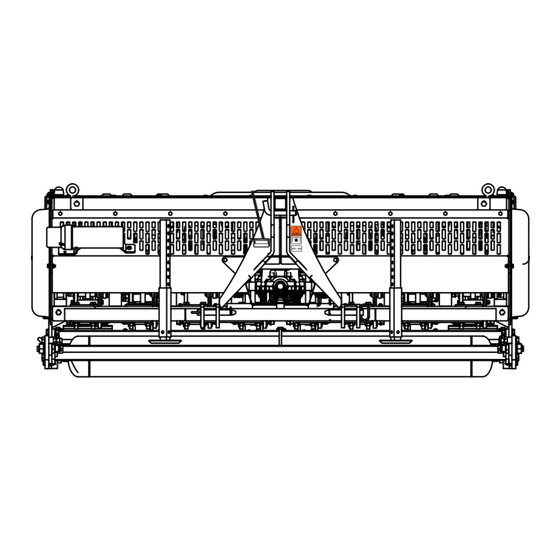
Page 48: Aerator Frame
GA580 Serial No. All 11.2.1 Aerator Frame... - Page 49 GA580 Item Part No. Qty. Description Serial Numbers/Notes 4352007 Hitch, 3 Point 4353086 Frame, Ladder 4357449 Bracket, Left Side Cover 4357448 Bracket, Right Side Cover 400420 Screw, 1/2-13 x 3-1/2” Hex Head 453017 Flat Washer, 1/2 800700 Nut, 1/2-13 Crownlock Flange...
-
Page 50: Aerator Drive
GA580 Serial No. All 11.3.1 Aerator Drive... - Page 51 GA580 Item Part No. Qty. Description Serial Numbers/Notes 4368006 Driveshaft, PTO See 11.9.1 4350028 Gearbox See 11.10.1 348088 Key, 5/16 x 1” Square 4350066 Sprocket, Coupler • Set Screw 4353446 Chain, #50 Two Strand Coupler • Master Link 4350070 Bearing, Gearbox Extension Shaft 4372186 Spacer, 1/2 x 1 x 1-13/16”...
-
Page 52: Crankshaft Assembly
GA580 Serial No. All 11.4.1 Crankshaft Assembly... - Page 53 GA580 Item Part No. Qty. Description Serial Numbers/Notes 4350074 Bearing, Crankshaft Main 4349291 Journal, Crankshaft Main Apply Anti-Seize Compound 400564 Screw, 3/8-16 x 1-1/2” Hex Head Grade 8 Torque to xx ft. lb., Blue Loctite 446142 Lockwasher, 3/8 Heavy Crank Arm Assembly 4349292 •...
-
Page 54: Roller
GA580 Serial No. All 11.5.1 Roller 23 31 4388306 4388306 4 IN 3.5 IN 3 IN 2.5 IN 2 IN 1.5 IN 1 IN 1 IN 1.5 IN 2 IN 2.5 IN 3 IN 3.5 IN 4 IN 101 MM... - Page 55 GA580 Item Part No. Qty. Description Serial Numbers/Notes 4387150 Plate, Roller Adjust Rack 4349108 Plate, Roller Lift 400390 Screw, 1-8 x 2-1/2” Hex Head 548173 Flat Washer 4355628 Spacer, 1 x 1-3/8 x 23/32” 400392 Nut, 1-8 Hex Jam Nyloc 400620 Screw, 5/8-11 x 2-1/2”...
-
Page 56: Tine Arms
GA580 Serial No. All 11.6.1 Tine Arms 10 10... - Page 57 GA580 Item Part No. Qty. Description Serial Numbers/Notes 4353246 Tine Arm Assembly Includes standard tine head 4349286 • Plate, Linkage Arm 4350100 • Pin, Tine Arm Wrist 4350071 • Bearing, Linkage Arm Insert 453022 • Flat Washer, 3/4 400397 • Nut, 3/4-10 Hex Nylock Jam 4353266 •...
-
Page 58: Tine Options
GA580 Serial No. All 11.7.1 Tine Options Solid Coring Tine Tines Shanks Coring Tines... - Page 59 GA580 Item Part No. Qty. Description Serial Numbers/Notes 4395696 Solid Tine, 3/8 x 6-1/2 in. 4395697 Solid Tine, 3/8 x 9-1/2 in. 4395698 Solid Tine, 12 mm x 6-1/2 in. ● 4395699 Solid Tine, 12 mm x 9-1/2 in. 4395700 Coring Tine, 9/16 x 6-1/8 in.
-
Page 60: Tine Head Options And Tools
GA580 Serial No. All 11.8.1 Tine Head Options and Tools Standard Tine Block for PTO Shaft Lock Three 8 mm or 5/16 in. Tines PTO Hanger Three 10 mm or 3/8 in. Shank Tines Two 12 mm or 1/2 in. Shank Tines... - Page 61 GA580 Item Part No. Qty. Description Serial Numbers/Notes 4358266 Tine Block, Standard 400549 Screw, 3/8-16 x 2-1/4” Hex Head 800698 Nut, 3/8-16 Flange Crownlock 4394568 Screw, 3/8-16 x 1-1/2” Hex Head 3/8 in. Tine Shanks 4394569 Screw, 3/8-16 x 1-1/4” Hex Head...
-
Page 62: Pto Shaft Breakdown
GA450 Serial No. All 11.9.1 PTO Shaft Breakdown ROTATING DRIVE SHAFT CONTACT CAN CAUSE DEATH KEEP AWAY! DO NOT OPERATE WITHOUT - ALL DRIVE SHAFT GUARDS, TRACTOR AND EQUIPMENT SHIELDS IN PLACE DRIVE SHAFT GUARDS THAT TURN FREELY ON DRIVE SHAFT READING OPERATOR’S MANUAL DO NOT USE PTO ADAPTERS... - Page 63 GA450 Item Part No. Qty. Description Serial Numbers/Notes Half, Joint and Shaft Guarded Tractor Side • Half, Joint and Shaft • Yoke, Push Pin Lock • Push Pin • Cross and Bearing Kit • Yoke, and Shaft • Tube, Inner Shaft •...
-
Page 64: 1Gearbox
GA580 Serial No. All 11.10.1 Gearbox... - Page 65 GA580 Item Part No. Qty. Description Serial Numbers/Notes Housing, Upper Housing, Lower Shaft, Input 20 Tooth Bevel Gear Shaft, Output 27 Tooth Bevel Gear Bearing, Inner Cup and Cone Bearing, Outer Cup and Cone Retaining Ring Seal, Oil Screw, SHCS...
- Page 66 INDEX 3004410.......46 4350086.......52 4383547 ...... 60 548902 ......46 310854......52 4350100.......56 4384812 ...... 46 548910 ......46 348088......50 4350146.......54 4384927 ...... 60 548911 ....46 351003......46 4350147.......54 4385034 ...... 46 58253 ......60 400150......48 435017......56 4385035 ...... 46 64163-12 ....50 400190......54 4352007.......48 4386911 ......
- Page 67 INDEX...
- Page 68 A worldwide dealer network and factory trained technicians backed by Genuine Jacobsen Parts provide reliable, high-quality product support. When Performance Matters. ™ Textron Specialized Vehicles 1451 Marvin Griffin Rd, Augusta, GA 30906 www.Jacobsen.com 800-848-1636...
Need help?
Do you have a question about the GA580 and is the answer not in the manual?
Questions and answers