Table of Contents
Advertisement
IAPMO R & T Certified
against NSF/ANSI 44
IAPMO R & T Certified
against CSA B483.1
89
UF/DF
Water Softener
1. Page 25 of this manual contains important maintenance procedures for the continued proper
operation of your unit. These MUST be performed regularly for your warranty to remain valid.
2. Read all instructions carefully before operation.
3. Avoid pinched o-rings during installation by applying NSF certified lubricant to all seals (provided with install kit).
4. This system is not intended for treating water that is microbiologically unsafe or of unknown quality without
adequate disinfection before or after the system.
Canada West
Canada East
855 Park St., Unit 1
490 Pinebush Rd., Unit 1
Regina, SK S4N 6M1
Cambridge, ON N1T 0A5
Series
U.S.A.
56 Lightcap Rd.
9760 Mayflower Park Drive,
Pottstown, PA 19464
Suite 110
Carmel, IN 46032
*
*Check the valve sticker
to make sure its UF (Upflow) or
DF (Downflow)
4655 McDowell Rd. W
Phoenix, AZ 85035
Advertisement
Table of Contents

Related Manuals for Hydrotech 89 UF Series


Summary of Contents for Hydrotech 89 UF Series
- Page 1 IAPMO R & T Certified against NSF/ANSI 44 IAPMO R & T Certified against CSA B483.1 Series UF/DF *Check the valve sticker to make sure its UF (Upflow) or Water Softener DF (Downflow) 1. Page 25 of this manual contains important maintenance procedures for the continued proper operation of your unit.
-
Page 3: Table Of Contents
READ THIS PAGE FIRST BEFORE STARTING INSTALLATION EFFICIENCY STATEMENT HOW YOUR WATER CONDITIONER WORKS SPECIFICATIONS SPECIFICATION SYSTEM DIMENSIONS BRINE TANK DIMENSIONS INSTALLATION UNPACKING / INSPECTION OF TWIN TANK MODEL UNPACKING / INSPECTION OF CABINET MODEL BEFORE INSTALLATION PREPARATIONS INSTALLING BRINE TANK WATER SOFTENER INSTALLATION - UPFLOW WATER SOFTENER INSTALLATION - DOWNFLOW CABINET WATER SOFTENER INSTALLATION - UPFLOW... -
Page 4: Read This Page First
READ THIS PAGE FIRST BEFORE STARTING INSTALLATION Read this manual thoroughly to become familiar with the Avoid pinched o-rings during installation by applying device and its capabilities before installing or operating your (provided with install kit) NSF certified lubricant to all seals. Water Softener. -
Page 5: Efficiency Statement
EFFICIENCY STATEMENT This product is efficiency rated according to NSF/ANSI 44. The stated efficiencies are valid only at the specified salt dosages and maximum service flow rate. PERFORMANCE DATA SHEET Model Number 89HE-75C 89HE-100C 89HE-75 89HE-100 89HE-150 89HE-200 89HE-300 Qty High Capacity Resin 0.75 ft3 1.0 ft3 0.75 ft3... -
Page 6: Specification
SPECIFICATION Upflow Softener Models Regeneration Water System Capacity Grains Flow Rate Usage (Gallons) Brine Tank / Salt Ship Mineral Resin Model Cabinet Size Capacity Weight Tank Size Cu. Ft. @ 10 lbs/ @ 6 lbs/cu ft @ 3 lbs/ Service Backwash Problem Clean Water... -
Page 7: System Dimensions
SYSTEM DIMENSIONS Models A (Inches) B (Inches) Twin Tank Model 53” 9” 57” 9" 63” 10" 61” 12" 63” 13" Cabinet Model... -
Page 8: Brine Tank Dimensions
BRINE TANK DIMENSIONS Model Color Liquid Volume Tank Dimensions 5 Pack Carton Salt Capacity 5 Pack Carton (inches) Dimensions (inches) Shipping Weight US Gal Liters L x W x H L x W x H Brine Tanks BTR-70 Black 20.3 76.5 15.8 x 32.1 16.7 x 16.7 x 61.0... - Page 9 BTR70 BTR100 BTR145 BTR200 salt tank lid salt tank body brine well and brine valve salt grid system salt grid system BTR 200l label (7.3") (20.35")
-
Page 10: Unpacking / Inspection Of Twin Tank Model
UNPACKING / INSPECTION OF TWIN TANK MODEL Be sure to check the entire unit for any shipping damage or parts loss. Also note damage to the shipping cartons. Contact the transportation company for all damage and loss claims. The manufacturer is not responsible for damages in transit. Small parts, needed to install the Softener, are in a parts box. - Page 11 For Models 250 and 300 the media and Control Valve is packaged separately in carton and bags What is included with 250 and 300 models? There are 7 Red clips. Please 1. Tank (Models 250 and 300 will get an Adapter and Oring attached to the tank) check to make sure you 2.
-
Page 12: Unpacking / Inspection Of Cabinet Model
UNPACKING / INSPECTION OF CABINET MODEL 1. Cabinet with Valve attached 2. Parts Box 3. Drain Line and Hose Clamp (Not Included with some models)) 1. Control Valve 1. Cabinet NOTE Due to transportation and climatic conditions all connections including the valve to the tank need to be checked at time of installation and tightened if... - Page 13 Check Valve Type and Valve Serial # Check to make sure the valve type is what you ordered. The serial # label on the left will show 890 (DF) for downflow valve and 890 (UF) for Upflow valve The right Sticker shows the serial # of the control valve.
-
Page 14: Before Installation
BEFORE INSTALLATION NOTE Make sure you have a copy of your most recent water test results. If your water has not been tested previously you can contact All government codes and your supplier of this product to obtain a water sample bottle to be sent to one of our facilities for a free analysis. It is important regulations governing the that this product not be installed until you have this information. -
Page 15: Preparations
CAUTION! PREPARATIONS The unit should be 1. Media Installation (When Necessary). Models including and higher than 2 CF (Models 250,300) of media are shipped with depressurized before separate media in pails or boxes. Models lower than 2 CF of media come loaded with media and this step can be skipped for installing or replacing media new installation. - Page 16 PREPARATIONS 1. Determine the best location for your water filter, bearing in mind the location of your water supply lines, drain line and 120 volt AC electrical outlet. Subjecting the filter to freezing or temperatures above 43°C (110°F) will void the warranty. Please notice the inlet and outlet valves as shown here to determine the position of the equipment: Inlet...
-
Page 17: Installing Brine Tank
INSTALLING BRINE TANK* a) Attach the three brine grid legs to grid plate. The c) Drop the brine grid with brine well inside the d) Take the brine tube and insert the nut and plastic sleeve as legs will snap on to the tabs of the salt plate making brine tank such that the nut fitting faces the shown below. -
Page 18: Water Softener Installation - Upflow
WATER SOFTENER INSTALLATION Connect Softener to the House Plumbing Any solder joints near the valve must be done before connecting any piping to the valve. Always leave at least 6” (152 mm) between the valve and joints when soldering pipes that are connected to the valve. Failure to do this could cause damage to the valve. Upflow Water Softener Installation Cold (Raw water) Cold (Raw water) -
Page 19: Water Softener Installation - Downflow
WATER SOFTENER INSTALLATION Connect Softener to the House Plumbing Any solder joints near the valve must be done before connecting any piping to the valve. Always leave at least 6” (152 mm) between the valve and joints when soldering pipes that are connected to the valve. Failure to do this could cause damage to the valve. Downflow Water Softener Installation Cold (Raw water) Cold (Raw water) -
Page 20: Cabinet Water Softener Installation - Upflow
CABINET WATER SOFTENER INSTALLATION Connect Softener to the House Plumbing Any solder joints near the valve must be done before connecting any piping to the valve. Always leave at least 6” (152 mm) between the valve and joints when soldering pipes that are connected to the valve. Failure to do this could cause damage to the valve. Upflow Cabinet Water Softener Installation Cold (Raw water) Cold (Raw water) -
Page 21: Cabinet Water Softener Installation - Downflow
CABINET WATER SOFTENER INSTALLATION Connect Softener to the House Plumbing Any solder joints near the valve must be done before connecting any piping to the valve. Always leave at least 6” (152 mm) between the valve and joints when soldering pipes that are connected to the valve. Failure to do this could cause damage to the valve. Downflow Cabinet Water Softener Installation Cold (Raw water) Cold (Raw water) -
Page 22: Startup Instructions
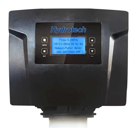
STARTUP INSTRUCTIONS 3. Screen Display 1. Connect the Transformer to the Valve Familiarize with Button Configuration: Plug the 12-volt transformer into a 120 VAC 60 Hz outlet. Date and Time 18-Apr-2018 10:35AM MENU Gal Remain 1400 Flow Rate 3 gpm/min The controller will show the following on the screen - Time, Date and Gallons Remaining for Regeneration... - Page 23 STARTUP INSTRUCTIONS (CONTINUED) 4. Manually Regenerate the Valve (Continued) 4a. Open the inlet on the bypass valve slowly and allow water to enter the unit. (The outlet of the bypass should remain closed to prevent any fines or debris from entering the plumbing system.
-
Page 24: During Regeneration
DURING REGENERATION Automatic Water Bypass The regeneration cycle lasts approximately 1.5 hours to 3.0 hours depending on the specific model, after which treated water service will be restored. During regeneration, untreated water is automatically bypassed for use in the household. Hot water should be used as little as possible during this time to prevent hard water from filling the water heater. -
Page 25: Maintenance Instructions And Schedule
MAINTENANCE INSTRUCTIONS AND SCHEDULE System Check List NOTE** All units are factory programmed for the correct size and regeneration cycle alteration should only be done by a factory trained technician or after consultation with one of our technical representatives if you have any questions please call: 1-866-874-2532 4a. -
Page 26: Important Warranty And Maintenance Information
MAINTENANCE INSTRUCTIONS AND SCHEDULE Checking the Salt Level Check the salt level monthly. Remove the lid from the cabinet or brine tank, make sure salt level is always above the brine level. CAUTION! Add Salt to the Brine Tank Put 40 kgs of crystal water softener salt in the brine tank. The unit will automatically fill the water to the correct level when it Incorrect start up, water regenerates. -
Page 27: Res-Up® Feeder Installation Instructions
Care of Your Softener To retain the attractive appearance of your new water softener, clean occasionally with a mild soap solution. Do not use abrasive cleaners, ammonia or solvents. Never subject your softener to freezing or to temperatures above 43°C (110°F). Servicing Components Ÿ The injector assembly should be cleaned or replaced every year depending on the inlet water quality and water usage. - Page 28 Res-Up® Feeder Installation Instructions Round Brine Tank - continued 4. IInstall the holder and the Res Care Solution 5. Take off the small hole cover on the Brine Well lid. 6. Take off the cover of the Res care bottle . Insert the wick, making sure it touches the bottom of the bottle.
-
Page 29: Servicing 89He Valve
4. IInstall the holder and the Res Care Solution 5. Take off the small hole cover on the Brine Well lid. 6. Take off the cover of the Res care bottle . Insert the wick, making sure it touches the bottom of the bottle. -
Page 30: Replacement
TIMER REPLACEMENT 4 X Screws Meter Cable Front Cover 1. Disconnect the meter cable from the meter. (If flow 2. Remove four screws from the back of the valve cover 3. Remove the front cover of the valve. meter is attached) Piston Screw Washer 2 X Screws from Powerhead... -
Page 31: Meter Assembly Replacement
METER ASSEMBLY REPLACEMENT (For Models Manufactured after Valve Serial # Date of November 2015) Meter Cable 2X Clips 1. Disconnect the meter cable from the meter. 4. Remove the meter support and then the impeller out from the coupling and 2. -
Page 32: Replacing The Bypass And Meter Cable
REPLACING THE BYPASS AND METER CABLE If valve is manufactured before March 20th, 2018, and customer wishes to replace or service impeller on bypass. Customer can order 60010238. If customer wishes to replace to new design, then follow the steps below. Grey Meter Cable 60010267 Bypass comes with Meter... -
Page 33: Clean Injector Assembly
CLEAN INJECTOR ASSEMBLY 1. Remove the two screws from the injector cap 2. Pull the injector cap and gasket 3. Pull the injector assembly and Screen 4. Replace/Clean screen and injector assembly and put it back in the valve in appropriate location as shown 5. -
Page 34: Circuit Board Replacement
CIRCUIT BOARD REPLACEMENT Circuit Board Screws Wire connections to Circuit Board 1. Remove the screws from the back of the valve and pull the front 2. Remove all connections from the circuit board cover 3. Remove the fours screws from the circuit board and pull it out REPLACE BRINE LINE FLOW CONTROL 1. -
Page 35: After Servicing
AFTER SERVICING 1. Reconnect drain line 2. Return bypass or inlet valve to normal in service position. Water Pressure will automatically build in the Softener 3. Check for leaks at all sealed areas. Check Drain seal with the control in the backwash position 4. - Page 36 PARTS BREAKDOWN Bypass Tool Parts Box 2 X 3/4” Elbow - 60010006 Adapter) - 60090010 Grease Packet - 92360 2X 1” Straight Adapter - 60090003 Transformer - 60010052 O Rings Attached Brine Tank Assembly (Round Brine Tank Shown)) Brine Tank Brine Tank (Round or Tubing...
-
Page 37: Parts
PARTS BREAKDOWN 89 UF and DF Power Head Parts List Part # Part # Description (Water Group) (Canature) 60010329 05033028 Micro Switch Cable 60010115 05010031 Meter Cable 60010124 05010029 Power Cable 60010330 05010046 Meter Cable Clip 60010331 05010035 Power Cable Clip 92393 05056550 Motor 12VAC 3W... -
Page 38: 89 Valve Body
PARTS BREAKDOWN Parts list of control valve body: Part # Part # Description (Water Group) (Canature) 60010184 21389033 Brine Line Elbow Nut 60010172 30020013M Brine Line Elbow 60010044 05056134 O-ring of Brine Line Elbow 60010188 05031033 O-ring of BLFC Holder 60010173 05031010M BLFC Holder... -
Page 39: Injector Part # For 89 Valve
PARTS BREAKDOWN DLFC PART # for 89 VALVE Part # Part Description 60095720 BNT95DLFC-0(4.0 GPM) 60010143 BNT95DLFC-1(7.0GPM) 60010144 BNT95DLFC-2(11.0GPM) 60010145 BNT95DLFC-3(14.0GPM) 60010146 BNT95DLFC-4(17.0GPM) 60010147 BNT95DLFC-5(21.0GPM) 60095692 BNT95DLFC-6(24.0GPM) 60095721 BNT95DLFC-1S(2.4GPM) 60095722 BNT95DLFC-2S(3.5GPM) 60095723 BNT95DLFC-3S(4.5GPM) 60010140 BNT95DLFC-4S(5.0GPM) 60095724 BNT95DLFC-5S(6.0GPM) 60095725 BNT95DLFC-6S(6.0GPM) 60010142 BNT95DLFC-7S(7.0GPM) BLFC PART # for 89 VALVE Part #... -
Page 40: Cabinet
PARTS BREAKDOWN Cabinet Parts List Part # Description Trim Strip Softener Cabinet(Grey) 60010361 Pressure Tank Clamp 25020019 TANK ASSY 935 NAT 25020020 TANK ASSY 1035 NAT 50010020 Distribution Assy-1035 18280 Top Cone 60010004 Bypass Valve Assy 60010255 Hose Barb 89(UF) Control Valve(Black) 55010031 Softener Low Cover 55010032... -
Page 41: Trouble Shooting Guide
TROUBLE SHOOTING GUIDE Problem Possible Solutions 1. CONDITIONER DELIVERS HARD WATER A. Close bypass valve A. Bypass valve is open B. Add salt to brine tank and maintain salt level above water level B. No salt in brine tank C. Replace injectors and screen C. -
Page 42: Programming
TROUBLE SHOOTING GUIDE Problem Possible Solutions 11. DRAIN FLOWS CONTINUOUSLY A. Remove piston assembly and inspect bore. Remove foreign material and check control in various regener- A. Foreign material in control ation positions B. Internal control leak B. Replace seals and/or piston assembly C. - Page 43 MASTER PROGRAMMING 89 DOWNFLOW VALVE (89 DF MODELS) The controller will show the following on the screen - Time, Date and number of Days Remaining for Regeneration: = Initial Setup Interface = = Initial Setup Interface = = Initial Setup Interface = = Initial Setup Interface = Language Language...
- Page 44 MASTER PROGRAMMING 89 UPFLOW VALVE (89UF MODELS) The controller will show the following on the screen - Time, Date and number of Days Remaining for Regeneration: = Initial Setup Interface = = Initial Setup Interface = = Initial Setup Interface = = Initial Setup Interface = Language Language...
- Page 45 MASTER PROGRAMMING GUIDE 89 DOWNFLOW ADVANCED MENU PRESS “MENU” KEY AND SCROLL TO “MAIN MENU”. THEN PRESS “SET” TILL IT BEEPS. SCROLL TO ADVANCED MENU Press “Menu” key . Press - to advance to Advanced Menu Press and hold “SET” 5 seconds or until you hear a beep.
- Page 46 ADVANCED MENU 89 UPFLOW PRESS “MENU” KEY AND SCROLL TO “MAIN MENU”. THEN PRESS “SET” TILL IT BEEPS. SCROLL TO ADVANCED MENU Press “Menu” key . Press - to advance to Advanced Menu Press and hold “SET” 5 seconds or until you hear a beep. Press “+” or “-”...
- Page 47 MAIN MENU 89 DOWNFLOW Press “Menu” key . Press - to advance to Advanced Menu Press and hold “SET” 5 seconds or until you hear a beep. Press “+” or “-” to choose menu option. Press “SET” to enter. Press “+” or “-”...
- Page 48 DIAGNOSTIC SCREEN PRESS “MENU” KEY AND SCROLL TO “MAIN MENU”. THEN PRESS “SET” TILL IT BEEPS. SCROLL TO ADVANCED MENU Press - to advance to History Values Press “Menu” key . Press - to advance to Main Menu Press“SET” or until you hear a beep. Press “SET”...
- Page 49 HOW TO SET DATE AND TIME AND MANUAL REGENERATION PRESS “MENU” KEY AND SCROLL TO “MAIN MENU”. THEN PRESS “SET” TILL IT BEEPS. Press “Menu” key Press “+” or “-” to change menu option. Press “SET” to enter. Press “+” or “-”...
- Page 52 TOLL FREE: 1-877-288-9888 • • • • Regina, SK Cambridge, ON Carmel, IN Pottstown, PA Phoenix, AZ 54577 11/18...
Need help?
Do you have a question about the 89 UF Series and is the answer not in the manual?
Questions and answers