Table of Contents
Advertisement
Quick Links
Keysight N5102A Baseband Studio Digital Signal
Interface Module
Due to our continuing efforts to improve our products through firmware and hardware
revisions, N5102A module design and operation may vary from descriptions in this
guide. We recommend that you use the latest revision of this guide to ensure you have
up-to-date product information. Compare the print date of this guide with the latest
revision, which can be downloaded from the following website:
http://www.keysight.com/find/basebandstudio
Notice: This document contains references to Agilent.
Please note that Agilent's Test and Measurement
business has become Keysight Technologies. For
more information, go to www.keysight.com.
Installation Guide
Advertisement
Table of Contents

Related Manuals for Keysight Technologies N5102A


Summary of Contents for Keysight Technologies N5102A
- Page 1 Due to our continuing efforts to improve our products through firmware and hardware revisions, N5102A module design and operation may vary from descriptions in this guide. We recommend that you use the latest revision of this guide to ensure you have up-to-date product information.
- Page 2 No part of this manual may be January 2015 duplication or disclosure of Software reproduced in any form or by any Published in USA is subject to Keysight Technologies’ means (including electronic storage standard commercial license terms, and retrieval or translation into a Keysight Technologies...
- Page 3 Where to Find the Latest Information Documentation is updated periodically. For the latest information about these products, including instrument software upgrades, application information, and product information, browse to one of the following URLs, according to the name of your product: http://www.keysight.com/find/basebandstudio To receive the latest updates by email, subscribe to Keysight Email Updates at the following URL: http://www.keysight.com/find/MyKeysight...
-
Page 5: Table Of Contents
Proper Usage and Cleaning ..............6 Connecting the N5102A Module to the ESG/PSG/X-Series (N5182B/72B) or N5101A PCI Card....8 Operation Verification . - Page 6 Returning an N5102A Module to Keysight Technologies ........
-
Page 7: Installation
— “Safety Information” on page 2 — “Getting Started” on page 4 — “Connecting the N5102A Module to the ESG/PSG/X-Series (N5182B/72B) or N5101A PCI Card” on page 8 — “Operation Verification” on page 11 — “Regulatory Information” on page 13... -
Page 8: Safety Information
It provides operational information or additional instructions of which the user should be aware. Instrument Markings The following markings are is used on the N5102A Baseband Studio digital signal interface module. Familiarize yourself with it and its meaning before operating the module. -
Page 9: General Safety Considerations
Installation Safety Information This symbol indicates that the input power required is DC. This symbol indicates compliance with the Canadian Interference-Causing Equipment Standard (ICES-001). General Safety Considerations Personal injury may result if the module cover is removed. There are no WARNING operator serviceable parts inside. -
Page 10: Getting Started
144.8 mm (5.70 in) Height: 41.6 mm (1.64 in) Meeting Electrical and Environmental Requirements The N5102A module is designed for use in the following environmental conditions: — indoor use — altitudes < 15,000 feet (4,572 meters) — 0 to 55°C temperatures, unless otherwise specified —... -
Page 11: Ventilation
POLLUTION DEGREE 2, per IEC 61010-1 and 664, respectively. Ventilation Ventilation holes are located on the front and rear panels of the N5102A module. Do not allow these holes to be obstructed, as they allow air flow through the module. -
Page 12: Connecting The Ac Power Cord
To avoid damage and personal injury, ensure that liquid substances are positioned away from your N5102A module. Personal injury may result if the N5102A module is not used as WARNING specified. Unspecified use impairs the protection provided by the equipment. - Page 13 Cleaning Suggestions To prevent dust build-up that could potentially obstruct ventilation, clean the N5102A module cover periodically. Use a dry cloth, or one slightly dampened with water, to clean the external case parts. To prevent electrical shock, disconnect the N5102A module from the WARNING mains supply before cleaning.
-
Page 14: Connecting The N5102A Module To The Esg/Psg/X-Series (N5182B/72B) Or N5101A Pci Card
PCI Card Connecting the N5102A Module to the ESG/PSG/X-Series (N5182B/72B) or N5101A PCI Card The N5102A digital signal interface module is used with an Keysight E4438C , E8267C PSG , E8267D PSG , X-Series (N5182B/72B), or a PC with an... - Page 15 1-3. Connect the AC power cord to both the power supply and the AC power source (for details on connecting an AC power cord to an AC power source, see “Connecting the AC Power Cord” on page 4. Connect the power supply to the N5102A module DC power receptacle.
- Page 16 If the power LED is not illuminated, check the AC power connection for the power supply and ensure that the DC power supply plug is fully inserted into the N5102A module DC power receptacle. If problems still persist after checking the power cords, refer to Chapter 4, “Troubleshooting”, on page...
-
Page 17: Operation Verification
“Running Diagnostic Tests” on page If your N5102A interface module is connected to an N5101A PCI card in a PC, operation verification occurs through the controlling software (for example, N5110B Baseband Stud io for waveform capture and playback). For more information, see the software’s documentation. - Page 18 Installation Operation Verification 4. On the signal generator, select the device interface test: Press Aux Fctn > N5102A Interface > Diagnostics > Loop Back Test Type > Device Intfc. As shown in Figure 1-6, the currently selected test is displayed in parenthesis below the Loop Back Test Type softkey.
-
Page 19: Regulatory Information
Assistance Product maintenance agreements and other customer assistance agreements are available for Keysight Technologies products. For any assistance, contact Keysight Technologies (see page 49). - Page 20 Installation Regulatory Information...
-
Page 21: Overview
Keysight Baseband Studio Digital Signal Interface Module N5102A Installation Guide Overview This chapter describes the features of the N5118A digital signal interface module along with the options required for its operation. — “Features” on page 16 — “Front Panel” on page 19 —... -
Page 22: Features
W-CDMA, multitone, 1xEV-DV, WLAN and many more, are available at the bit level for testing digital components, transceivers, and subsystems. The N5102A module delivers the digital IQ or digital IF signals to your device with the data requirements, clock features, and signaling you need. - Page 23 — interchangeable break-out boards When connected to an ESG, PSG, or X-Series (N5182B/72B) signal generator the parameters for the N5102A module are set using the user interface (UI) on the ESG/PSG/X-Series (N5182B/72B). This provides familiar softkey operation for both the modulation format and the interface module. Option 003 (output mode) and Option 004 (input mode) on the ESG/PSG/X-Series (N5182B/72B) enable the N5102A module user interface on the signal generators.
- Page 24 With the capability of connecting an N5102A module to a signal generator or an N5101A PCI card, you can perform multiple levels of testing. Since the...
-
Page 25: Front Panel
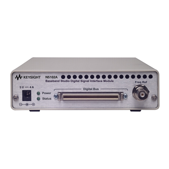
Front Panel Front Panel The baseband data and frequency reference inputs for the N5102A module are located on the front panel along with the receptacle for the DC power. A Power LED indicates when DC power has been applied and a Status LED shows when the data lines are active. -
Page 26: Digital Bus Connector
Overview Front Panel 4. Digital Bus Connector The N5102A module uses this connector to communicate with the ESG, PSG, X-Series (N5182B/72B), or PCI card. A proprietary three-meter digital bus cable is supplied that connects to the Digital Bus connector. 5. Freq Ref Connector When Internal is the selected clock source, the clock is referenced to this 50W connector. -
Page 27: Rear Panel
Overview Rear Panel Rear Panel The rear panel has three connectors that are shown in Figure 2-2 and are described in the following sections. Figure 2-2 Rear Panel Features... -
Page 28: Ext Clock In Connector
1. Ext Clock In Connector This AC coupled 50W connector is used for connecting an external clock source to the N5102A module. It accepts a signal with a nominal amplitude of 0 dBm and has a frequency range of 1 MHz to 400 MHz. -
Page 29: Device Interface Connections
Keysight Baseband Studio Digital Signal Interface Module N5102A Installation Guide Device Interface Connections This chapter provides information for the N5102A module Device Interface connector, the supplied break-out boards, and the device interface mating connector. — “Break-Out Boards” on page 24 —... -
Page 30: Break-Out Boards
To maximize signal integrity, make the device connection as close as possible to the N5102A module Device Interface connector. The break-out boards are supplied to aid in minimizing this distance. An alternate solution is to incorporate the device interface mating connector onto the device under test (DUT). -
Page 31: Dual 20-Pin Break-Out Board
Device Interface Connections Break-Out Boards Table 3-2 Connector Part Numbers and Manufacturers Connector Break-out Board Output Mating Connector Manufacturer Part Manufacturer Type Connector Manufacturer Part Number Number 20-Pin 2520-6002UB 3421-6700 (wire connector) 38-Pin Mictor 2-767004-2 767006-1 (board connector) Tyco Electronics 40-Pin 2540-6002UB 3417-6700 (wire connector) - Page 32 Device Interface Connections Break-Out Boards Figure 3-1 Dual 20-Pin 0.1 Spaced Connector...
-
Page 33: Dual 38-Pin Break-Out Board
Device Interface Connections Break-Out Boards Dual 38-Pin Break-Out Board This board is intended for differential testing, however it can also be used for single-ended signals. For single-ended signals, the data is transmitted on the positive lines. Figure 3-2 shows this break-out board along with the pin-out diagram for the connectors. - Page 34 Device Interface Connections Break-Out Boards Figure 3-2 Dual 38-Pin Mictor Connector...
-
Page 35: Dual 40 Pin Break-Out Board
This board serves a dual function, one as a break-out board simplifying the connectivity of the device under test and the other as a loop back test board when performing N5102A module diagnostic tests. The VCCIO (selected high logic level voltage) is obtained at J3, while the + 5 volt unfiltered DC supply is acquired at J4. -
Page 36: Single 68-Pin Scsi Style Break-Out Board
For the N5102A module to receive a clock through the Device Interface connector by way of this break-out board, a zero-ohm resistor must be installed between the 66 to C2 contacts. This is shown in Figure 3-4. -
Page 37: Dual 100-Pin Break-Out Board
Device Interface Connections Break-Out Boards Dual 100-Pin Break-Out Board This break-out board is intended for differential testing, however it can also be used for single-ended signals. For single-ended signals, the data is transmitted on the positive lines. Figure 3-5 shows this break-out board along with the pin-out diagram for the connectors. - Page 38 Device Interface Connections Break-Out Boards Figure 3-5 Dual 100-Pin Samtec Connector...
-
Page 39: Device Interface Connector
Device Interface Connections Device Interface Connector Device Interface Connector The figures and information shown in this section will assist when customizing a connection solution for the device under test using the device interface mating connector (see “Device Interface Mating Connector” on page 38). - Page 40 Device Interface Connections Device Interface Connector Figure 3-7 Device Interface Connector Pin-Out...
- Page 41 Device Interface Connections Device Interface Connector Figure 3-8 Device Interface Connector Pin-Out (continued)
-
Page 42: Input And Output Clock Signals
Input and Output Clock Signals There are multiple output clock lines and two input clock lines to handle differential clocking. The N5102A module can be configured to accept the device under test clock through the Device Interface connector for data clocking. -
Page 43: Dc Supply
Device Interface Connections Device Interface Connector DC Supply Referring to Figure 3-6, notice that the interface module provides an unfiltered +5 volts DC supply through the Device Interface connector. This DC supply provides up to 100 mA and has a self-resettable fuse. Use this DC current to bias components on the device under test where the noise will not compromise test results. -
Page 44: Device Interface Mating Connector
34 Figure 3-8 on page 35. These figures display the pin-out diagrams for the N5102A module Device Interface connector. Table 3-6 provides the manufacturer and the part numbers for the Device Interface connector and its mate. Both connectors are available from suppliers external to Keysight Technologies. - Page 45 Device Interface Connections Device Interface Mating Connector Figure 3-9 Z-Dok+ Device Interface Mating Connector Layout and Footprint...
- Page 46 Device Interface Connections Device Interface Mating Connector Figure 3-10 Z-Dok+ Device Interface Mating Connector PC Board Foot Print...
-
Page 47: Troubleshooting
This chapter provides the following information to assist you in troubleshooting the N5102A Baseband Studio digital signal interface module: — “If You Encounter a Problem” on page 42 — “Replaceable Parts” on page 48 — “Returning an N5102A Module to Keysight Technologies” on page 49... -
Page 48: If You Encounter A Problem
When connected to a PCI card, read the controlling software’s error message and resolve any problems identified in the message. Refer to the software’s online help for more information. If the N5102A module is not operating properly, refer to the following table to begin troubleshooting. Symptom... -
Page 49: Checking Power Problems
9) and the DC power supply plug is fully inserted into the N5102A module DC power receptacle If this does not solve the problem, go to step 2 to check the power supply. 2. Using a DVM, check the power supply output. -
Page 50: Running Diagnostic Tests
Device Interface (System) Test This is a comprehensive test that checks the paths from the signal generator Digital Bus connector to the Device Interface connector on the N5102A module. This is the same test used in the section, “Operation Verification” on page 11, which describes the test in more detail. - Page 51 3. Select and run the Device Interface test: a. On the signal generator, press Aux Fctn > N5102A Interface > Diagnostics > Loop Back Test Type > Device Intfc. Note that the test selection in parentheses below the Loop Back Test Type softkey updates to reflect the current test.
- Page 52 N5102A Digital Bus Test This test checks the communication path from the Digital Bus connector on the signal generator to the input of the N5102A module. It does not require the use of a loop back test board. 1. If not already done, disconnect the Loop Back Test Single Ended IO Dual 40 Pin board from the N5102A module.
- Page 53 Troubleshooting If You Encounter a Problem Results: Pass The N5102A module has a problem, send the module to Keysight for service (see page 49). Fail Perform the Signal Generator Digital Bus test to further isolate the problem. Signal Generator Digital Bus Test...
-
Page 54: Replaceable Parts
United States and Canada, 120V 8120-1521 Differential I/O Dual 100 Pin Board N5102-63017 Switzerland 8120-2296 Single Ended I/O 68 Pin Board N5102-63018 Denmark 8120-2957 N5102A Installation Guide N5102-90003 South Africa and India 8120-4600 Power Supply, AC-DC 5V 4A 0950-4540 Japan 8120-4754 Israel 8120-5181... -
Page 55: Returning An N5102A Module To Keysight Technologies
Returning an N5102A Module to Keysight Technologies Returning an N5102A Module to Keysight Technologies To return your N5102A digital signal interface module to Keysight Technologies for servicing, follow these steps: 1. Gather as much information as possible regarding the module’s problem. -
Page 56: Contacting Keysight Technologies
Troubleshooting Contacting Keysight Technologies Contacting Keysight Technologies There is support on the world-wide web. The address is: http://www.keysight.com/find/support FAQs, instrument software updates, documentation, and other support information can be accessed from this site. To obtain servicing information or to order replacement parts, contact the... - Page 57 Troubleshooting Contacting Keysight Technologies Table 4-1 Contacting Keysight www.keysight.com/find/contactus Online assistance: Americas Country Phone Number Canada (877) 894 4414 Brazil 55 11 3351 7010 Mexico 001 800 254 2440 United States 1 800 829-4444 Asia Pacific Country Phone Number Australia...
- Page 58 Troubleshooting Contacting Keysight Technologies Europe and Middle Country Phone Number Luxembourg +32 800 58580 Netherlands 0800 0233200 Russia 8800 5009286 Spain 0800 000154 Sweden 0200 882255 Switzerland 0800 805353 Opt. 1 (DE) Opt. 2 (FR) Opt. 3 (IT) United Kingdom...
- Page 59 & mating break-out boards connectors connector part numbers contacting Keysight Technologies differential testing contents dual 100-pin customer assistance dual 20-pin dual 38-pin dual 40-pin...
- Page 60 ESG/PSG test loop back fixture Keysight Technologies module test Sales and Service offices dimensions, instrument dual connector break-out boards 100-pin LEDs 20-pin power 38-pin status 40-pin...
- Page 61 Index required signal generator SCSI style connector, 68-pin output clock signals shipment output mode option signal generator overview, module error queue, clearing error queue, reading messages required options part numbers signal interface features break-out board connectors single 68-pin break-out board device interface single-ended testing mating connectors...
- Page 62 ventilation requirements verification, operation voltage requirements width, instrument Z-Dok+...
Need help?
Do you have a question about the N5102A and is the answer not in the manual?
Questions and answers