
Related Manuals for Stevens AeroModel SQuiRT-700


Summary of Contents for Stevens AeroModel SQuiRT-700
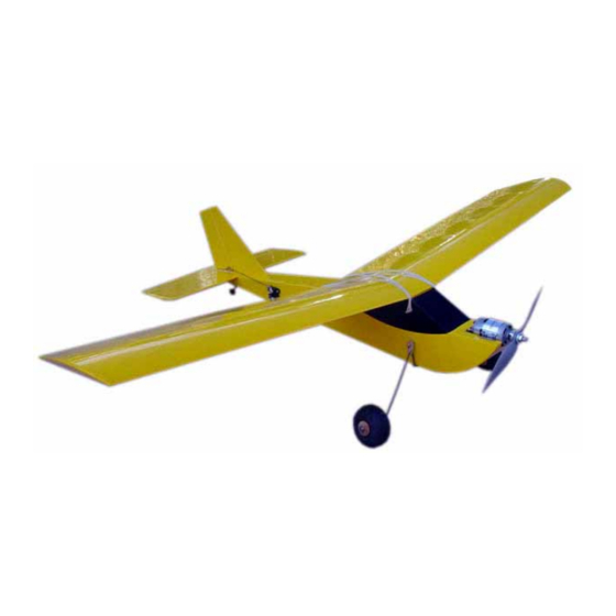
- Page 1 SQuiRT-700 A Speed 700 Primary Trainer R1.01 Span 57” / Length 39” / Area 560 Sq.” / Flying Weight 40-48 oz. © 2005 Stevens AeroModel all rights reserved.
-
Page 2: Warranty
Further, Stevens AeroModel reserves the right to change or modify this warranty without notice. In that Stevens AeroModel has no control over the final assembly or material used for final assembly, no liability shall be assumed nor accepted for any damage resulting from the use by the user of the final user-assembled product. - Page 3 • 1 - 9-10 NIMH or 3S1P 11.1v Apogee LiPo 2480mAh (or any other 11.1v lipo capable of 25A Continuous). *Included with Squirt+PS kits. Available as a stand alone motor kit from Stevens AeroModel www.stevensaero.com Brushless Motor Upgrades: NONE Suggested.
- Page 4 GENERAL ASSEMBLY INSTRUCTIONS: Thank you, for purchasing this Stevens Aeromodel SQuiRT 700 – A speed 700 primary trainer. This kit provides the builder and pilot a refreshing change of pace from heavy “ARF” style plywood box airframe construction and blends stick and tissue design methods of the past with state of the art CAD technology and precision interlocking laser cut parts;...
- Page 5 Assemble Fuselage Sides from 1/8” Balsa parts: Fa, Fb, and Fc. Use the following image as a guide. Fill/Sand the joints to a smooth finish. Assemble fuselage cross grain components F7 from F7a and F7b. © 2005 Stevens AeroModel all rights reserved.
- Page 6 CA glue into adjoining surfaces. Invert the core assembly and add the 1/16” plywood motor mount doubler F1a to the inside of the core assembly as pictured below. © 2005 Stevens AeroModel all rights reserved.
- Page 7 Repeat for the opposite side. Tip! you must fit F5 to the core prior to joining the fuselage sides. Now install the F7 cabin cross grain doublers (assembled previously). These parts key inside the fuselage as indicated in the photo below. © 2005 Stevens AeroModel all rights reserved.
- Page 8 Install F13 cross-grain doubler behind former F5 on the INSIDE of the fuselage assembly. Match the " holes in F13 to those in the fuselage side. Do this after installing F9 but prior to installing F11. © 2005 Stevens AeroModel all rights reserved.
- Page 9 13. Use the 3/32” balsa assembly of parts F11 and F14 from the previous step. Key to the fuselage as indicated in the photo below with the ply doubler F14 on the INSIDE of the fuselage. Once satisfied with the fit, square the assembly to your work table and secure with thin CA glue. © 2005 Stevens AeroModel all rights reserved.
- Page 10 F11. Tip! Sand lightly if the fit is too snug (a result of the C1,2,3 parts not being aligned properly when gluing) – don’t force the parts to fit. © 2005 Stevens AeroModel all rights reserved.
- Page 11 19. You’ll notice that the upper deck slightly overhangs the front of the windshield. Using a medium grit sand paper and your sanding block sand off the overhang as indicated in the photos below. © 2005 Stevens AeroModel all rights reserved.
- Page 12 #64 band on either side of the fuselage. You may adjust the gear tension by adding or removing wraps of the rubber band. Remove the exterior metal shield from your Speed 700 motor as illustrated below: © 2005 Stevens AeroModel all rights reserved.
- Page 13 You’ll need to drill your APC 10x5e prop hub using a 5/16” drill to fit the propeller adapter. Once you have reamed the prop hub to 5/16”, install the appropriate sized precision adapter included with your APC 10x5e propeller. Balance the propeller and install to the motor as illustrated. © 2005 Stevens AeroModel all rights reserved.
- Page 14 Additionally, part W1 is etched indicating where the inner R1 rib will meet W1. Next add the 3/32” ribs R3 at each tip of the wing as indicated in the photo below. © 2005 Stevens AeroModel all rights reserved.
- Page 15 W5 aligns with the notching in the W1 parts. Locate the two 1/16” ply spars S2 and install to both the FRONTSIDE and the BACKSIDE of the balsa spar S1. Reference this photo and the plan sheet for placement detail. © 2005 Stevens AeroModel all rights reserved.
- Page 16 TE1 to the outside edge of ribs R1 and TE2 as illustrated below. Locate the 1/16” ply trailing edge doubler part TE3 and glue into position aligned with the notch in the back side of the wing trailing edge as indicated in the following photo. © 2005 Stevens AeroModel all rights reserved.
- Page 17 R3. Once satisfied with the fit glue W3 into position. 12. Sheet the center section of the wing using the following 3/32” balsa parts W6, W7, and W8 following the plan sheet and photo series below as a reference. © 2005 Stevens AeroModel all rights reserved.
- Page 18 W2. Once the glue has set you can continue to wrap each cap strip down and back along each rib one at a time. 15. Install the 3/32” balsa wing tip cap stripping part W4 as indicated in the photo below. © 2005 Stevens AeroModel all rights reserved.
- Page 19 17. Now you need to sand the trailing edge of each of the upper W10 cap strips and W4 to “disappear” at the trailing edge of the wing. Refer to the photos below for guidance. A sanding block is STRONGLY suggested for this step. © 2005 Stevens AeroModel all rights reserved.
-
Page 20: Covering The Model
Remember more rubber bands increases the tension on the wing and will make it more likely to break in a crash. 12. Test your radio setup for function and proceed on to first flight. © 2005 Stevens AeroModel all rights reserved. -
Page 21: First Flight
Next, trim the plane in roll. Using the rudder trim tab on your transmitter add left or right rudder trim until the plane tracks a straight line. 10. The SQuiRT carries energy very well and will glide in nicely for simple landings once the plane has been trimmed. 11. Enjoy your SQuiRT! © 2005 Stevens AeroModel all rights reserved.
Need help?
Do you have a question about the SQuiRT-700 and is the answer not in the manual?
Questions and answers