Advertisement
Quick Links
Advertisement

Subscribe to Our Youtube Channel
Related Manuals for Stevens AeroModel SE5.a


Summary of Contents for Stevens AeroModel SE5.a
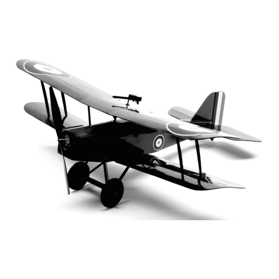
- Page 1 Britain's WWI Anti-Tyranny Aerial Platform Wing Span: 14.5 inches | Wing Area: 76 square inches | Average Flying Weight: 1.6 ounces Build Instructions - Version 1.0 (revised 05.13.2014) SE5.a UM Build Instructions. © 2013 Stevens AeroModel all rights reserved.! Page 1...
- Page 2 Build Instructions WARRANTY Stevens AeroModel guarantees this kit to be free from defects in both material and workmanship at the date of purchase. This warranty does not cover any component parts damaged by use or modification. In no case shall Stevens AeroModel’s liability exceed the original cost of the purchased kit. Further, Stevens AeroModel reserves the right to change or modify this warranty without notice.
- Page 3 1 - 1-1/2 in length of Heat Shrink Tube 1 - Nylon Receiver Clip 1 - Acetate Windscreen (Laser Cut) 1 - Pair 1-1/8 in. Plastic Wheels [SIGSH540] SE5.a UM Build Instructions. © 2013 Stevens AeroModel all rights reserved.! Page 3...
- Page 4 ☐ DEFT clear lacquer based sealant (available at most hardware stores). ☐ Design Master Color Tool lacquer based spray paint (available at most art supply stores). SE5.a UM Build Instructions. © 2013 Stevens AeroModel all rights reserved.! Page 4...
- Page 5 Build Instructions Sheet Wood Inventory (1 of 1) SE5.a UM Build Instructions. © 2013 Stevens AeroModel all rights reserved.! Page 5...
- Page 6 Build Instructions Builders Notes SE5.a UM Build Instructions. © 2013 Stevens AeroModel all rights reserved.! Page 6...
- Page 7 Build Instructions General Assembly Instructions Thank you, for purchasing this Stevens SE5.a UM. This product has been developed and manufactured using state of the art CAD/CAM systems and features a unique interlocking construction process that, when compared to traditional methods found in other model aircraft kits, save countless hours of measuring, cutting, sanding, and fitting.
- Page 8 F6 and F7 to be fitted in the next steps. Landing Gear Pocket Fit the landing gear brace F6 to the over sized slots in F5, immediately behind F2. Do not □ bond. SE5.a UM Build Instructions. © 2013 Stevens AeroModel all rights reserved.! Page 8...
- Page 9 Build Instructions Nylon Clip Bottom Step 1 Step 5 Bottom View “Slug” Bottom Step 2 Step 6 Bottom Step 7 Step 3 Step 4 Step 8 Bottom SE5.a UM Build Instructions. © 2013 Stevens AeroModel all rights reserved.! Page 9...
- Page 10 Fit and tack glue the aft fuselage bottom F13 the notches in the fuselage sides forward of □ F3, and to the tabs at the bottom of F3. SE5.a UM Build Instructions. © 2013 Stevens AeroModel all rights reserved.! Page 10...
-
Page 11: Table Of Contents
Build Instructions Step 9 Step 13 Bottom View “Slug” Step 10 Step 14 Bottom View Step 11 Step 15 Step 12 Bottom View Step 16 SE5.a UM Build Instructions. © 2013 Stevens AeroModel all rights reserved.! Page 11... -
Page 12: Step
Position F17 over F16 and repeat the process given “Step 20” above to align and bond F17 □ over F16. Fit the center stringer F18 to the center notches in F3 and F15. Bond with CA. □ SE5.a UM Build Instructions. © 2013 Stevens AeroModel all rights reserved.! Page 12... -
Page 13: Step
Build Instructions Bottom View Step 17 Step 20 Bottom View Step 17 cont. Step 21 Top View Step 18 Step 22 Step 19 Step 22 cont. SE5.a UM Build Instructions. © 2013 Stevens AeroModel all rights reserved.! Page 13... -
Page 14: Step
F24 coming together at the top of F22. Now do not bond, instead, hold F24 in place with low tack masking tape until completely dry. SE5.a UM Build Instructions. © 2013 Stevens AeroModel all rights reserved.! Page 14... -
Page 15: Step
Step 23 Step 27 Moisten this side with glass cleaner Step 24 Step 28 Tabs Step 25 Step 29 Tape and allow to dry. Step 26 Step 30 SE5.a UM Build Instructions. © 2013 Stevens AeroModel all rights reserved.! Page 15... -
Page 16: Step
“Step 38” for a better understanding of the positioning of these paired ribs. SE5.a UM Build Instructions. © 2013 Stevens AeroModel all rights reserved.! Page 16... - Page 17 Sand in line with center stringer Step 32 Step 35 Round 45 deg. Step 32 cont. Step 36 Round In line with bottom of Step 33 Step 37 fuselage F11 SE5.a UM Build Instructions. © 2013 Stevens AeroModel all rights reserved.! Page 17...
- Page 18 If you have mixed the part orientation of W5 up you’ll want to pay careful attention and work directly over the plan to make a right and left panel. SE5.a UM Build Instructions. © 2013 Stevens AeroModel all rights reserved.! Page 18...
- Page 19 Build Instructions Paired Ribs Step 38 Step 42 Step 39 Step 43 Step 40 Step 44 Step 41 Step 45 SE5.a UM Build Instructions. © 2013 Stevens AeroModel all rights reserved.! Page 19...
- Page 20 Bond the Spreader LG3 ONLY to the Landing Gear Struts with medium CA. Do not bond the Landing Gear Struts to the fuselage at this time. SE5.a UM Build Instructions. © 2013 Stevens AeroModel all rights reserved.! Page 20...
- Page 21 Build Instructions Step 46 Step 50 Step 47 Step 51 Bottom View Step 48 Step 52 Step 49 Bottom View Step 53 SE5.a UM Build Instructions. © 2013 Stevens AeroModel all rights reserved.! Page 21...
- Page 22 As viewed from the top, sand the sides of the headrest until they taper to a point in the □ center of HR1. □ Now, sand the top of the headrest to match the contour of HR3. SE5.a UM Build Instructions. © 2013 Stevens AeroModel all rights reserved.! Page 22...
- Page 23 Step 54 Step 57 M2 “Magazine” M1 “Machine Gun” Step 55 Step 58 Taper Step 56 Top View Step 59 Contour Notch Step 56 cont. Step 60 SE5.a UM Build Instructions. © 2013 Stevens AeroModel all rights reserved.! Page 23...
- Page 24 Make up the markings from the appropriately colored trim. Or simply purchase the optional trim package (available from StevensAero.com), and apply in the positions indicated on the plan sheets at this time. SE5.a UM Build Instructions. © 2013 Stevens AeroModel all rights reserved.! Page 24...
-
Page 25: Bottom View Step
Edge Optional Wheels and Covers Step 62 Round Step 63 Step 67 Leave bottom uncovered until after pushrod installation. Bevel Step 64 Bottom View Step 67 cont. SE5.a UM Build Instructions. © 2013 Stevens AeroModel all rights reserved.! Page 25... - Page 26 Pre-installation of the motor is completely acceptable just follow steps 73, 74, and 75 as given above and be careful when sanding the model not to damage the gearbox shaft. SE5.a UM Build Instructions. © 2013 Stevens AeroModel all rights reserved.! Page 26...
- Page 27 Step 68 Step72 Outer-Left hole Remove Spikes Bottom View Step 69 Step 73 Exit slot Step 70 Step 74 Step 71 Servo Tabs Bottom View Step 75 Glue SE5.a UM Build Instructions. © 2013 Stevens AeroModel all rights reserved.! Page 27...
- Page 28 Rudder on the left side. Fit and bond a control horn to the slot in the Tail Skid, extending from the right side of the □ Rudder. SE5.a UM Build Instructions. © 2013 Stevens AeroModel all rights reserved.! Page 28...
- Page 29 Heads Step 76 Step 80 Bottom View Cover Step 77 Step 81 Left side Headrest Step 81 cont. Step 75 Step 79 Windscreen Right side Step 82 SE5.a UM Build Instructions. © 2013 Stevens AeroModel all rights reserved.! Page 29...
- Page 30 Bond the strut assembly to the fuselage with Medium CA. Do not bond the landing gear wires to the struts as they must be free to flex and absorb some of the shock of landing. SE5.a UM Build Instructions. © 2013 Stevens AeroModel all rights reserved.! Page 30...
- Page 31 Bottom View Step 83 Step 87 Step 84 Step 88 Step 85 Bottom View Step 89 Bottom View Glue Bond Bottom View Step 86 Step 90 Bond SE5.a UM Build Instructions. © 2013 Stevens AeroModel all rights reserved.! Page 31...
- Page 32 Do not bond the jig to the wing assembly! SE5.a UM Build Instructions. © 2013 Stevens AeroModel all rights reserved.! Page 32...
- Page 33 Build Instructions Step 91 Step 95 Step 96 Step 92 Bond Bond Step 93 Step 96 cont. Step 94 Step 97 W17/W16 Do Not Bond! SE5.a UM Build Instructions. © 2013 Stevens AeroModel all rights reserved.! Page 33...
- Page 34 104. Fit the machine gun assembly to the two small holes near the center section trailing edge, □ and bond with medium CA. Don’t shoot your eye out! SE5.a UM Build Instructions. © 2013 Stevens AeroModel all rights reserved.! Page 34...
- Page 35 Tack glue Step 97 cont. No glue! Bond Bond Step 98 Step 102 Break off Tack Step 99 Step 103 Step 100 Step 104 Caution! Bond SE5.a UM Build Instructions. © 2013 Stevens AeroModel all rights reserved.! Page 35...
- Page 36 Remember, we just provided the canvas so you can take on personalizing your model as you see fit. What ever finishing method you choose I hope you have enjoyed building the SE5.a UM as much as I have and that you have found it to be an innovative and thoughtful kit product.
- Page 37 Build Instructions EFL9051 Step 105 Put the “Baron” on notice... Complete! SE5.a UM Build Instructions. © 2013 Stevens AeroModel all rights reserved.! Page 37...
- Page 38 ☐ Inspect battery for full charge. Never begin a flight with a partially charged battery. ☐ Clear prop! Before applying power to the model, clear and keep clear of the prop arc. SE5.a UM Build Instructions. © 2013 Stevens AeroModel all rights reserved.! Page 38...
- Page 39 Congratulations! You’ve completed your first flight(s) on your Stevens Aero SE5.a UM. By now you’ll have noticed that the SE5.a UM is a very stable airplane. When built straight, and trimmed for level flight, the model will always return to wings level from any attitude.
Need help?
Do you have a question about the SE5.a and is the answer not in the manual?
Questions and answers