Table of Contents
Advertisement
Quick Links
Download this manual
See also:
User Manual
Advertisement
Table of Contents

Related Manuals for Anaheim Scientific E200


Summary of Contents for Anaheim Scientific E200
- Page 1 Model E200 3-Axis RF Field Strength Meter GlobalTestSupply www. .com Find Quality Products Online at: sales@GlobalTestSupply.com...
-
Page 2: Table Of Contents
Table of Contents AXIS RF METER QUICK START GUIDE ..........4 INTRODUCTION ................5 The E200 Features ..............5 E201 Applications ..............6 SAFETY SUMMARY ................. 7 EMF SAFETY ..................8 COMPLIANCE STATEMENTS ............9 PRODUCT CONTENTS AND INSPECTION ........9 DEVICE DESCRIPTION .............. - Page 3 10.3 DEL Data Logger Memory Setup-3 ......... 23 10.4 Analog bar graph setup-4 ............24 10.5 Auto Power-Off Function Setup-5 ..........25 10.6 Setting the calibration factor (CAL)-6 ........26 10.7 Calibration Factor (CAL) ............27 MAKING MEASUREMENTS ............27 11.1 Short-term Measurements ............
-
Page 4: Axis Rf Meter Quick Start Guide
Axis RF Meter Quick Start Guide This meter has many capabilities, including memory, alarm, date/time, average etc. which will require some study of the manual to use properly. However, you can quickly and easily begin making measurements right out of the box. Just follow these simple steps: •... -
Page 5: Introduction
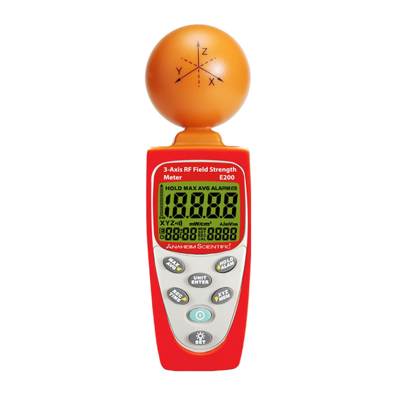
Introduction Thank you for purchasing an E200 3-Axix RF Field Strength Meter from Anaheim Scientific. This meter is designed for measuring and monitoring Radio– Frequency electromagnetic field strength. The meter is calibrated precisely over the frequency range of 50Mz~3.5 GHZ. -
Page 6: E201 Applications
• High dynamic range due to three-channel digital results processing. • Configurable alarm threshold and memory function. • Easy & safe to use • Low battery indicator “ ”. • Manual data memory storing: 200 data sets. • Over load indication “OL”. 1.2 E201 Applications •... -
Page 7: Safety Summary
Safety Summary CAUTION Adhere to the following conditions for safe and effective usage of this meter • Do not operate the meter in an environment filled with combustible gas, liquids, dust or fibers • In order to avoid reading incorrect data, please replace the battery immediately when the symbol “... -
Page 8: Emf Safety
EMF Safety • In some cases, work in the vicinity of powerful radiation sources can be life threatening. • Be aware that persons with electronic implants (e.g. cardiac pacemakers) are subject to particular dangers in some cases. • Observe the local safety regulations of the facility. •... -
Page 9: Compliance Statements
Compliance Statements Caution: This symbol indicates that the equipment and its accessories are subject to special collection and disposal procedures • This tester was designed in accordance with EMC Standards in force and its compatibility has been tested in accordance with EN61326-1 (2006) Class B •... - Page 10 Use of the original packing is essential. After the mechanical inspection, verify the contents of the shipment. The items included in this package are: • E200 Meter • User manual • 9V battery • Carrying case GlobalTestSupply www.
-
Page 11: Device Description
Device Description 1. 3-Axis RF Sensor 2. LCD 3. MAX / AVG / R Button 4. Record / Time / L Button 5. Power Button 6. UNIT / ENTER switch Button 7. Hold / ALARM On/Off / Up Button 8. Backlight/Set 9. -
Page 12: Lcd Description
LCD Description 1. Primary Display 13. E symbol 2. Hold symbol 14. Auto power off symbol 3. Analogue bar graph 15. Time unit (month:day) 4. MAX symbol (hour: minute) (second) 5. AVG symbol 16. MEM reading symbol 6. Low battery symbol 17. -
Page 13: Fundamentals
Fundamentals 8.1 Electromagnetic Pollution This meter is used to indicate electromagnetic pollution generated artificially. Wherever there is a voltage or a current, electric (E) and magnetic (H) fields arise. All types of radio broadcasting and TV transmitters produce electromagnetic fields, and they also arise in industry, business and the home, where they affect us even if our sense organs perceive nothing. -
Page 14: The Characteristic Of Electromagnetic Fields
square meter (W/m ) or, for convenience, units such as milliwatts per square centimeter (mW/cm 8.5 The Characteristic of Electromagnetic Fields Electromagnetic fields propagate as waves and travel at the speed of light (C). The wavelength is proportional to the frequency. λ... -
Page 15: Device Operation
Device Operation 9.1 Battery replacement WARNING If the symbol “ ” appears on the LCD, please replace the battery immediately • Turn off the instrument. • Remove the battery cover • Replace the battery. • Install the battery cover. • Be sure to turn unit off after use to conserve battery life. -
Page 16: Data Hold Button
9.3 Data Hold Button Press the “ ” button to go into hold mode, and “HOLD” appears on the screen to allow you to read the data. Press the “ ” button once again to deactivate it. 9.4 Units Button Change units with the “UNITS”... -
Page 17: Max / Avg Record
9.5 MAX / AVG Record Press “ ” key to switch to the next display. The display switches from MAX to AVG to MAX/AVG and back to MAX. Press and hold “ ” key for 3 seconds to disable this function. -
Page 18: Backlight Display And Reading In The Dark
9.7 Backlight Display and Reading in The Dark Press the “ ” key to turn the backlight on. Press “ ” again to turn it off. The backlight turns off automatically after 30 seconds. 9.8 Sensor Axis Selector: Press ” ”... -
Page 19: Viewing Data Records
and hold ” ” and “ ” keys to turn off the alarm function. When the Alarm sounds, the display shows 9.10 Viewing Data Records Press and hold the “ ” button and press the “ ” button to view the saved data records. Use “ ”... -
Page 20: Setup Mode
This meter’s clock uses 24 hour time setting. Default time mode setting is “2010/01/07 00: 02” “:00”. Setup Mode Press and hold “ ” button and then “ ” button to enter the setup mode. Press “ ” button to scroll through the setup functions. -
Page 21: Clock Setup-1
• Setup 5: Auto Power-Off Time Function Setup-5 • Setup 6: Setting the Calibration Factor (CAL)-6 10.1 Clock Setup-1 Press and hold the “ ” button and then press “ ” button to enable Clock Setup. This meter clock is 24 hour time setting. Use “... -
Page 22: Setting The Alarm Limit Value (Alarm)-2
10.2 Setting the Alarm Limit Value (ALARM)-2 The alarm limit value determines the level at which the alarm will sound. The alarm limit value can be edited only in the V/m unit. The ALARM setting range is from 0.001 to 999.9V/m. ALARM default is set at 999.9V/m. -
Page 23: Del Data Logger Memory Setup-3
Press “ ” button 1 more time to enter the alarm setting mode, the readout value is flashing and ”V/m” unit is displayed. Press “ ” key to move decimal. Press “ ” key to select the desired digit. Press “ ”... -
Page 24: Analog Bar Graph Setup-4
will show on the display. To exit without clearing memory, press “ ” key To clear the memory, press “ ” then press “ ”. 10.4 Analog bar graph setup-4 While the meter in ON, press and hold the “ ”... -
Page 25: Auto Power-Off Function Setup-5
Press “ ” key to store the new setting value and exit. 10.5 Auto Power-Off Function Setup-5 While the meter is on, press and hold the “ ” button and press “ ” button to enter the auto power-off setup mode. Press “ ”... -
Page 26: Setting The Calibration Factor (Cal)-6
10.6 Setting the calibration factor (CAL)-6 Press “ ” button and press “ ” button to enter Setup Mode. Press “ ” button 5 more times to enter the calibration factor setup mode. The CAL setting range is from 0.10 to 9.99. Default is 1.00 which is appropriate for most situations. -
Page 27: Calibration Factor (Cal)
10.7 Calibration Factor (CAL) The calibration factor CAL serves to calibrate the display for a specific frequency when the frequency of a single signal is known. The field strength value measured internally is multiplied by the value of CAL that has been entered and the resulting value is displayed. -
Page 28: Short-Term Measurements
11.1 Short-term Measurements Application: Use either the “instantaneous” or the “Max. instantaneous” mode if the characteristics and orientation of the field are unknown when entering an area exposed to electromagnetic radiation. Procedure: Hold the meter at arm’s length. Make several measurements at various locations around your work place or the interested areas as described above. -
Page 29: Specifications
Specifications 12.1 General Specifications Display Type Liquid-crystal (LCD), 4-1/2 digits, maximum reading 19999 Measurement Method Digital, triaxial measurement Directional Type Isotropic (triaxial) Range Selection One continuous range Resolution 0.1mV/m, 0.1µA/m, 0.001µW/m 0.001µW/cm Setting Time Typically 1.5s (0 to 90% measurement value) Sample Rate 3 times per second Units... -
Page 30: Electrical Specifications
12.2 Electrical specifications Unless otherwise stated, the following specifications hold for the following conditions: • The meter is located in the far field of a source • Sensor head is pointed towards the source • Ambient Temperature: +23 °C, ±3°C •... -
Page 31: Units Of Measurement
12.3 Units of Measurement The meter measures the electrical component of the field; the default units are those of electrical field strength (mV/m or V/m). The meter converts the measurement values to the other units of measurement, i.e. the corresponding magnetic field strength units (µA/m or mA/m) and power density units (µW/m mW/m or µW/cm... -
Page 32: Service, Repairs, Calibration
Package the unit carefully using filler or bubble wrap, and if possible, ship in the original box. Ship each unit separately. (Anaheim Scientific is not responsible for any shipping damage that may occur.) GlobalTestSupply www. - Page 33 • If the unit is out of warranty, prepayment is required by Check, Money Order or Credit Card. • Return all merchandise to Anaheim Scientific with pre-paid shipping. The flat-rate repair charge for Non-Warranty Service does not include return shipping.
-
Page 34: Limited Two-Year Warranty
The warranty is void if the serial number is altered, defaced or removed. • Anaheim Scientific shall not be liable for any consequential damages, including without limitation damages resulting from loss of use. Some states do not allow limitations of incidental or consequential damages.
Need help?
Do you have a question about the E200 and is the answer not in the manual?
Questions and answers