
Related Manuals for Anaheim Scientific E201


Summary of Contents for Anaheim Scientific E201
- Page 1 Model E201 Wide Range RF Field Strength Meter 1.800.561.8187 information@itm.com www. .com...
-
Page 2: Table Of Contents
Table of Contents E201 METER QUICK START GUIDE ..........4 INTRODUCTION ................5 The E201 Features: ..............5 E201 Applications: ..............6 SAFETY SUMMARY ................. 7 EMF SAFETY ..................8 COMPLIANCE STATEMENTS ............9 PRODUCT CONTENTS AND INSPECTION ........9 DEVICE DESCRIPTION .............. - Page 3 10.11 Clock LCD Display ..............20 SETUP MODE ................. 20 11.1 Clock Setup-1 ................21 11.2 Setting the Alarm Limit Value (ALARM)-2 ....... 22 11.3 DEL Data Logger Memory Setup-3 ......... 23 11.4 Analog Bar Graph Setup-4 ............24 11.5 Auto Power-Off Function Setup-5 ..........
-
Page 4: E201 Meter Quick Start Guide
E201 Meter Quick Start Guide This meter has many capabilities, including memory, alarm, date/time, average etc. which will require some study of the manual to use properly. However, you can quickly and easily begin making measurements right out of the box. Just follow these simple steps: •... -
Page 5: Introduction
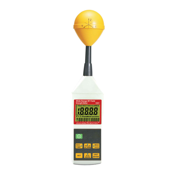
Introduction Thank you for purchasing the E201 Wide Range RF Field Strength Meter from Anaheim Scientific. This meter is designed for measuring and monitoring Radio– Frequency electromagnetic field strength. Compact, durable and easy to use. 2.1 The E201 Features: • The meter is a broadband device for monitoring high-frequency radiation in the range from 10MHz to 8GHz. -
Page 6: E201 Applications
• Low battery indicator “ ”. • Manual data memory storing: 200 data sets. • Memory over load indication “OL”. 2.2 E201 Applications: • High frequency (RF) electromagnetic wave field strength measurement • Mobile phone base station antenna radiation power density measurement •... -
Page 7: Safety Summary
Never use a wet cloth, solvents or water, etc. • Weather conditions outside the specified limits and improper handling may adversely affect the accuracy and function of the meter. Technical data subject to change without notice ©Anaheim Scientific 2013. 20130805 1.800.561.8187 information@itm.com www. -
Page 8: Emf Safety
Before using field strength measuring devices, you should thus be certain that all field components to be measured lie in the specified frequency range of the measuring device. Technical data subject to change without notice ©Anaheim Scientific 2013. 20130805 1.800.561.8187 information@itm.com www. -
Page 9: Compliance Statements
If damage to the instrument is evident, a description of the damage should be noted on the carrier’s receipt and signed by the driver or carrier agent. Save all shipping packaging for inspection. Technical data subject to change without notice ©Anaheim Scientific 2013. 20130805 1.800.561.8187 information@itm.com www. - Page 10 Use of the original packing is essential. After the mechanical inspection, verify the contents of the shipment. The items included in this package are: • E201 Meter • User manual • 9V battery • Carrying case •...
-
Page 11: Device Description
6. XYZ / MEM / Down Button 7. Power Button 8. REC/ Time / Leftward Button 9. SET Button 10. Tripod Mounting screw 11. Battery Cover Technical data subject to change without notice ©Anaheim Scientific 2013. 20130805 1.800.561.8187 information@itm.com www. .com... -
Page 12: Lcd Description
11. µA/m , A/m unit (H) 24. BUZZER symbol 12. µW/m / µW/cm unit 25. Decimal point 13. E Symbol 14. Auto power off symbol Technical data subject to change without notice ©Anaheim Scientific 2013. 20130805 1.800.561.8187 information@itm.com www. .com... -
Page 13: Fundamentals
(A/m). In far field situations, one can calculate the magnetic field using the electric field value. This meter can display the calculated magnetic field strength. Technical data subject to change without notice ©Anaheim Scientific 2013. 20130805 1.800.561.8187 information@itm.com www. -
Page 14: Power Density (S)
In near-field conditions, the magnetic field value cannot be calculated from the electric field value. This meter is designed for reliable far-field measurements only. Technical data subject to change without notice ©Anaheim Scientific 2013. 20130805 1.800.561.8187 information@itm.com www. -
Page 15: Device Operation
• Be sure to turn unit off after use to conserve battery life. 10.2 Power Key: Press “ ” key to turn ON the meter. Press “ ” key again to turn power OFF. Technical data subject to change without notice ©Anaheim Scientific 2013. 20130805 1.800.561.8187 information@itm.com www. .com... -
Page 16: Data Hold Key
10.3 Data Hold Key: Press the “ ” key to go into hold mode, and “HOLD” appears on the screen to allow you to read the data. Press “ ” key once again to deactivate it. >> > >> > 10.4 Units Key: Change units with the “UNITS”... -
Page 17: Max / Avg Record
” key, the meter will save the current measured result, and REC with a number 001~200 will appear. Manual data memory storing: 200 data sets. Over load Indication: “OL”. Technical data subject to change without notice ©Anaheim Scientific 2013. 20130805 1.800.561.8187 information@itm.com www. .com... -
Page 18: Xyz/Call
Press and hold “ ” and“ ” keys to turn off the alarm function. When the Alarm sounds, the display shows Technical data subject to change without notice ©Anaheim Scientific 2013. 20130805 1.800.561.8187 information@itm.com www. .com... -
Page 19: Viewing Data Records
10.9 Viewing Data Records Press and hold the “ ” key and press the “ ” key to view the saved data records. Use “ ” or “ ” key to see the next or previous records. Press the “ ”... -
Page 20: Clock Lcd Display
10.11 Clock LCD Display Press and hold the “ ” and “ ” keys to select the display method of the Year, Month, Date, hour and Second. This meter’s clock uses 24 hour time setting. Default time mode setting is “2010/01/07 00: 02” “:00”. Setup Mode Press and hold “... -
Page 21: Clock Setup-1
• Setup 3: Clear Data Logger Memory-3 • Setup 4: Analogue Bar Graph Setup-4 • Setup 5: Auto Power-Off Time Function Setup-5 • Setup 6: Setting the Calibration Factor (CAL)-6 11.1 Clock Setup-1 Press and hold the “ ” key first and then the “ ”... -
Page 22: Setting The Alarm Limit Value (Alarm)-2
11.2 Setting the Alarm Limit Value (ALARM)-2 The alarm limit value determines the level at which the alarm will sound. The alarm limit value can be edited in only in the V/m unit. The ALARM setting range is from 0.001 to 999.9V/m. ALARM default is set at 999.9V/m. -
Page 23: Del Data Logger Memory Setup-3
Setup Mode. Press “ ” key twice to enter the default display ’ ’’. Press “ ” or “ ” key to select Technical data subject to change without notice ©Anaheim Scientific 2013. 20130805 1.800.561.8187 information@itm.com www. .com... -
Page 24: Analog Bar Graph Setup-4
Press “ ” key to delete the memory and exit. Press “ ” or “ ” key to select ’ ’’ and then press “ ” to keep the memory and exit. 11.4 Analog Bar Graph Setup-4 Press and hold the “ ”... -
Page 25: Auto Power-Off Function Setup-5
” keys to change to: 00~99 minutes. Press “ ” key to save and exit. : 00 Auto power-off disable. : 99 Maximum auto power-off time Technical data subject to change without notice ©Anaheim Scientific 2013. 20130805 1.800.561.8187 information@itm.com www. .com... -
Page 26: Setting The Calibration Factor (Cal)-6
11.6 Setting the Calibration Factor (CAL)-6 Press “ ” key first and then “ ” key to enter the Setup Mode. Press “ ” key five times to display the “CAL SET ” the default factor. Default is 1.00 which is appropriate for most situations. -
Page 27: Calibration Factor (Cal)
• If the sensor is moved quickly, excessive field strength values could be displayed. This effect is caused by electrostatic charges. • Recommendation: hold the meter steady during the measurement. anaheimscientific.c Technical data subject to change without notice ©Anaheim Scientific 2013. 20130805 1.800.561.8187 information@itm.com www. .com... -
Page 28: Making Measurements
For example, the cables used in diathermy equipment may also radiate electromagnetic energy. Note that metallic objects within the field may locally concentrate or amplify the field from a distant source. Technical data subject to change without notice ©Anaheim Scientific 2013. 20130805 1.800.561.8187 information@itm.com www. -
Page 29: Long-Term Exposure Measurements
Note: Use the “Average” or” Max average” modes only when the instantaneous measurement values are fluctuating greatly. You may fix the meter to a wooden or plastic tripod Technical data subject to change without notice ©Anaheim Scientific 2013. 20130805 1.800.561.8187 information@itm.com www. -
Page 30: Specifications
Specifications 13.1 General Specifications Display Type Liquid-crystal (LCD), 4-1/2 digits, maximum reading 19999 Measurement Digital, triaxial measurement Method Directional Type Isotropic (triaxial) Range Selection One continuous range Resolution 0.1mV/m, 0.01V/m, 0.1µA/m, 0.1mA/m, 0.001µW/m , 0.01mW/ m , 0.001µW/cm Setting Time Typically 1.5s (0 to 90% measurement value) Sample Rate 1.5 times per second... -
Page 31: Electrical Specifications
±1.0dB (1.9 GHz to 3.5GHz) Isotropy deviation • Typically ±1.0dB (2.45GHz) Overload limit • 0.083mW/cm , (17.7 V/m) per axis Overload limit • (0 to 50°C): ±0.2dB Technical data subject to change without notice ©Anaheim Scientific 2013. 20130805 1.800.561.8187 information@itm.com www. .com... -
Page 32: Units Of Measurement
Maximum instantaneous (MAX): The digital display shows the highest instantaneous value measured, the “MAX “symbol is displayed. Technical data subject to change without notice ©Anaheim Scientific 2013. 20130805 1.800.561.8187 information@itm.com www. .com... -
Page 33: External Dc Power
13.5 External DC Power External AC to DC adapter: Voltage: 9V DC (8~14VDC Max) Output current: 500mA Socket: Center Pin Positive Outer Diameter 5.5mm; Internal Diameter 2.1 mm Technical data subject to change without notice ©Anaheim Scientific 2013. 20130805 1.800.561.8187 information@itm.com www. .com... -
Page 34: Service, Repairs, Calibration
• If the unit is out of warranty, prepayment is required by Check, Money Order or Credit Card. • Return all merchandise to Anaheim Scientific with pre-paid shipping. The flat-rate repair charge for Non-Warranty Service does not include return shipping. - Page 35 • For overnight shipments and non-North American shipping fees please contact Anaheim Scientific 1.800.561.8187 information@itm.com www. .com...
-
Page 36: Limited Two-Year Warranty
The warranty is void if the serial number is altered, defaced or removed. • Anaheim Scientific shall not be liable for any consequential damages, including without limitation damages resulting from loss of use. Some states do not allow limitations of incidental or consequential damages.
Need help?
Do you have a question about the E201 and is the answer not in the manual?
Questions and answers