Table of Contents
Advertisement
Quick Links
INSTALLATION MANUAL
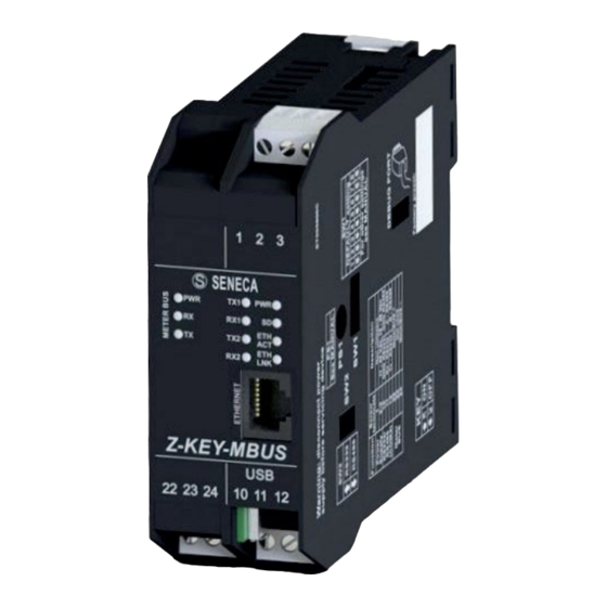
Z-KEY-MBUS
MeterBUS to Serial / Ethernet MODBUS gateway
E
SENECA s.r.l.
Via Austria, 26 – 35127 – PADOVA – ITALY
Tel. +39.049.8705355 - 8705359 - Fax +39.049.8706287
For manuals in other languages and the configuration software, visit
www.seneca.it/products/z-key-mbus
This document is the property of SENECA srl. Copies and reproduction are prohibited unless authorised. The
content of this document corresponds to the described products and technologies. Stated data may be modified
or supplemented for technical and/or sales purposes.
MI005230-E
ISTRUZIONI IN LINGUA ORIGINALE
ENGLISH - 1/8
Advertisement
Table of Contents

Related Manuals for Seneca Z-KEY-MBUS


Summary of Contents for Seneca Z-KEY-MBUS
- Page 1 For manuals in other languages and the configuration software, visit www.seneca.it/products/z-key-mbus This document is the property of SENECA srl. Copies and reproduction are prohibited unless authorised. The content of this document corresponds to the described products and technologies. Stated data may be modified or supplemented for technical and/or sales purposes.
-
Page 2: Technical Specifications
TECHNICAL SPECIFICATIONS EN61000-6-4 Electromagnetic emissions, industrial environment. STANDARDS EN61000-6-2. Electromagnetic immunity, industrial environment. EN60950 -1 Safety. IDC10 RJ45 USB 1500 VA RS485 INSULATION MeterBUS RS232 POWER SUPPLY ENVIRONMENTAL CONDITIONS -20°– + 65°C Temperature 30%– 90% non condensing. Humidity -20 – + 85°C Storage temperature IP20. -
Page 3: Preliminary Warnings
WARNING: The full content of this manual must be read before operation. The module must only be used by qualified electricians. Specific documentation is available at www.seneca.it/prodotti/z--key-mbus. The module must be repaired and damaged parts replaced by the Manufacturer. The product is sensitive to electrostatic discharges;... - Page 4 1 2 3 4 5 6 SENECA hooks on the side of the IDC10 rear connector as illustrated in Fig. 1a. DI3 ETH Z-KEY-MBUS micro 22 23 24 10 11 12 Fig. 1b Removal from the OMEGA IEC EN 60715 rail:...
-
Page 5: Electrical Connections
For the connection it is possible to use a two-wire shielded telephone cable or an unshielded duplex cable following the indications in the table. If a shielded cable is used, this must be connected to earth only from the Z-KEY-MBUS side. ENGLISH - 5/8... -
Page 6: Module Layout
Z- KEY-MBUS section. To access the maintenance Web Server, connect with a browser to the maintenance page at the IP address of the Z-KEY-MBUS, for example: http://192.168.90.101 and, when requested, enter the following credentials: Username: admin Password: admin. - Page 7 LED SIGNALS ON THE FRONT PANEL Status LED meaning TX1 (Red) Flashing Data transmission on COM1 RS485 port RX1 (Red) Flashing Data reception on COM1 RS485 port TX2 (Red) Flashing Data transmission on COM2 RS485 or RS232 port RX2 (Red) Flashing Data reception on COM2 RS485 or RS232 port Device powered...
-
Page 8: Inserting The Sd Card
SENECA I D 2 I D 3 I D 4 The module has a microUSB I socket on the front panel. Z-KEY-MBUS 19 20 21 The figure shows where to insert the micro-USB connector. micro 22 23 24 10 11 12 For more information see the USER MANUAL.
Need help?
Do you have a question about the Z-KEY-MBUS and is the answer not in the manual?
Questions and answers