CIB UNIGAS R91A Manual Of Installation - Use - Maintenance
Progressive/fully modulating
Hide thumbs
Also See for R91A:
- Installation, use & maintenance manual (149 pages) ,
- Manual of installation - use - maintenance (132 pages)

Related Manuals for CIB UNIGAS R91A


Summary of Contents for CIB UNIGAS R91A
- Page 1 R91A - R92A - R93A R512A -R515A R520A - R525A Gas burners Progressive / Fully modulating MANUAL OF INSTALLATION - USE - MAINTENANCE BURNERS - BRUCIATORI - BRULERS - BRENNER - QUEMADORES - ГОРЕЛКИ M039209CG Rel. 6.0 03/2015...
-
Page 2: General Introduction
DANGERS, WARNINGS AND NOTES OF CAUTION THIS MANUAL IS SUPPLIED AS AN INTEGRAL AND ESSENTIAL PART OF THE PRODUCT AND MUST BE DELIVERED TO THE USER. INFORMATION INCLUDED IN THIS SECTION ARE DEDICATED BOTH TO THE USER AND TO PERSONNEL FOLLOWING PRO- DUCT INSTALLATION AND MAINTENANCE. -
Page 3: Directives And Standards
DIRECTIVES AND STANDARDS do not leave the equipment exposed to weather (rain, sun, etc.) Gas burners unless expressly required to do so; European directives: do not allow children or inexperienced persons to use equipment; - Directive 2009/142/EC - Gas Appliances; The unit input cable shall not be replaced by the user. -
Page 4: Symbols Used
-EN 55014-1Electromagnetic compatibility - Requirements for household appliances, electric tools and similar apparatus. -UNI EN 676 (Gas Burners; -CEI EN 60335-1(Household and similar electrical appliances - Safety. Part 1: General requirements; - EN 50165 Electrical equipment of non-electric appliances for household and similar purposes. -
Page 5: General Features
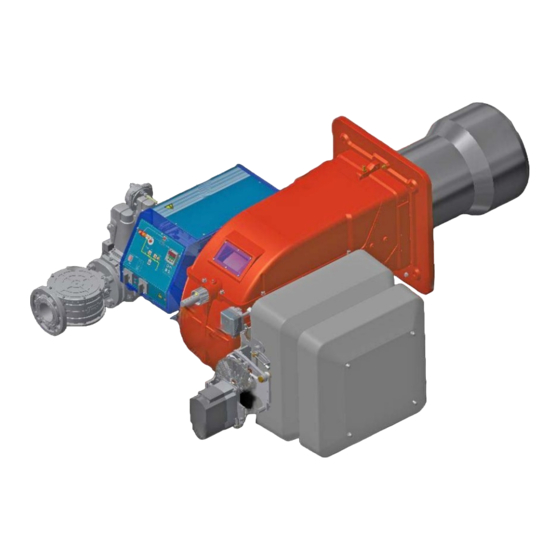
PART I: SPECIFICATIONS PART I: SPECIFICATIONS 1.0 GENERAL FEATURES Note: the figure is indicative only Control panel with startup switch Gas train Electrical panel Cover Blast tube + Combustion head Flange Silencer Adjusting cam Actuator 10 Air pressure switch 11 Combustion head adjusting ring nut The gas coming from the supply line, passes through the valves group provided with filter and stabiliser. -
Page 6: Gas Connection
Burners are identified by burner type and model. Burner model identification is described as follows. R91A MD. S. Type Model R91A, R92A, R93A, R512A, R515A, R520A, R525A BURNER TYPE FUEL M - Natural gas L - LPG OPERATION (Available versions) -
Page 7: Burner Type
PART I: SPECIFICATIONS 2.2 Technical Specifications BURNER TYPE R91A M-... R92A M-... R93A M-... 480 - 2670 480 - 3050 550 - 4100 Output min. - max. kW Natural gas Fuel see next paragraph Category Natural gas 51 - 283... - Page 8 PART I: SPECIFICATIONS BURNER TYPE R512A M-... R515A M-... R520A M-... R525A M-..50 R525A M-..xx 600 - 4500 770 - 5200 1000 - 6400 2000 - 6700 2000 - 8000 Output min. - max. kW Natural gas Fuel see next paragraph Category 63 - 476 81 - 550...
- Page 9 Burner flange Boiler recommended drilling tem- plate AA AD AN Omin Omax R91A 1495 242 35 550 100 441 1005 421 1160 435 265 295 228 450 360 464 M12 424 300 532 148 384 624 190 649 228 185...
- Page 10 Burner flange Boiler recommended drilling template AA AD AN 1683 320 35 595 100 530 517 1153 446 1590 644 340 380 494 540 494 M14 552 390 390 763 149 614 845 190 764 311 270 1683 320 35 611 117 530 517 1153 446 1613 644 340 380 494 540 494 M14 552 390 390 636 149 487 845 292 764 311 270 R512A 1683 320 35 626 132 530 517 1153 446 1646 1002 644 340 380 494 540 494 M14 552 390 390 687 149 538 875 310 764 311 270...
- Page 11 PART I: SPECIFICATIONS 2.5 How to read the burner “Performance curve” To check if the burner is suitable for the boiler to which it must be instal- Campo di lavoro bruciatori lled, the following parameters are needed: Tipo P60 Mod. M-xx.x.IT.A.0.50 - M-.xx.x.IT.A.0.65 furnace input, in kW or kcal/h (kW = kcal/h / 860);...
- Page 12 PART I: SPECIFICATIONS 2.7 Performance Curves R91A R92A 1200 1600 2000 2400 2800 3200 1200 1600 2000 2400 2800 R93A R512A 500 1000 1500 2000 2500 3000 3500 4000 4500 1500 2500 3500 4500 R515A R520A 1500 2500 3500 4500...
- Page 13 PART I: SPECIFICATIONS 2.8 Pressure in the Network / gas flow rate curves (natural gas) R91A M-.. R92A M-.. R93A M-.. R512A M-.. R515A M-.. R520A M-.. R525A M-.. Rp2 R525A M-.. DN65-80-100 Caution: the gas rate value is quoted on the x-axis, the related network pressure is quoted on the y-axis (pressure value in the combustion chamber is not included).
- Page 14 PART I: SPECIFICATIONS 2.9 Pressure in the Network / gas flow rate curves(LPG) R91A L-.. R93A L-.. R512A L-.. R520A L-.. Caution: the gas rate value is quoted on the x-axis, the related network pressure is quoted on the y-axis (pressure value in the combustion chamber is not included).
- Page 15 PART I: SPECIFICATIONS 2.10 Combustion head gas pressure curves depending on the flow rate The curves referred to the gas pressure in the combustion head, depending on the gas flow rate, are referred to the burner properly adjusted (percentage of residual O in the flues as shown in the “Recommended combustion values”...
- Page 16 PART I: SPECIFICATIONS 2.12 Pressure - rate in combustion head curves (natural gas) Curves are referred to pressure = 0mbar in the combustion chamber! R91A M-.. R92A M-.. 100 120 140 160 180 200 220 240 260 280 300 40 60 80 100 120 140 160 180 200 220 240 260 280 300 320 340 R93A M-..
- Page 17 PART I: SPECIFICATIONS 2.13 Pressure - rate in combustion head curves (LPG) Curves are referred to pressure = 0mbar in the combustion chamber! R91A L-.. R93A L-.. 100 110 120 130 140 150 160 R512A L-.. R520A L-.. 1 0 0...
- Page 18 PART II: INSTALLATION PART II: INSTALLATION 3.0 MOUNTING AND CONNECTING THE BURNER 3.1 Packing The burners are despatched in wooden crates whose dimensions are: 9xA series: 1672mm x 1072mm x 1016mm (L x P x H) 5xxA series: 1886mm x 1456mm x 1120mm (L x P x H) Packing cases of this type are affected by humidity and are not suitable for stacking.
- Page 19 PART II: INSTALLATION 3.3 Fitting the burner to the boiler To install the burner into the boiler, proceed as follows: make a hole on the closing door of the combustion chamber as described on paragraph “Overall dimensions”) place the burner to the boiler: lift it up and handle it according to the procedure described on paragraph “Handling the burner”; place the 4 stud bolts (5) on boiler’s door, according to the burner drilling template described on paragraph “Overall dimensions”;...
- Page 20 PART II: INSTALLATION spacer to move the burner backwards or to design a blast tube tha suites the utilisation (please, contact the manifacturer). a) Heat output in kW b) Lenght of the flame tube in meters c) Flame tube firing intensity in MW/m d) Combustion chamber diameter (m) Fig.
- Page 21 PART II: INSTALLATION 4.0 GAS TRAIN CONNECTIONS The diagrams show the components of the gas trai included in the delivery and which must be fitted by the installer.The diagrams are in compliance with the current laws. ATTENTION: BEFORE EXECUTING THE CONNECTIONS TO THE GAS PIPE NETWORK, BE SURE THAT THE MANUAL CUTOFF VALVES ARE CLOSED.
- Page 22 PART II: INSTALLATION 4.1 Assembling the gas grain gas supply network ”direction” arrows for installation Keys 1A..1E Gasket Gas filter Gas valves group Bellows unit Manual valve Fig. 6 - Example of gas train To mount the gas train, proceed as follows: 1-a) in case of threaded joints: use proper seals according to the gas used;...
- Page 23 PART II: INSTALLATION 4.2 Siemens VGD20.. and VGD40.. gas valves - with SKP2.. (pressure governor) Mounting When mounting the VGD.. double gas valve, two flanges are required (as for VGD20.. model, the flanges are threaded); to prevent cuttings from falling inside the valve, first fit the flanges to the piping and then clean the associated parts; install the valve;...
- Page 24 PART II: INSTALLATION ATTENTION: it is reccomended to install the filter with gas flow parallel to the floor in order to prevent dust fall on the safety valve during maintenance operation. Integrated proving system (burners equipped with LME7x, LMV, LDU) This paragraph describes the integrated proving system operation sequence: At the beginning both the valves (EV1 and EV2) must be closed.
-
Page 25: Electrical Connections
PART II: INSTALLATION 5.0 ELECTRICAL CONNECTIONS WARNING! Respect the basic safety rules. make sure of the connection to the earthing system. do not reverse the phase and neutral connections. fit a differential thermal magnet switch adequate for connection to the mains. - Page 26 PART III: OPERATION PART III: OPERATION WARNING: before starting the burner up, be sure that the manual cutoff valves are open and check that the pres- sure upstream the gas train complies the value quoted on paragraph “Technical specifications”. Be sure that the mains switch is closed.
- Page 27 PART III: OPERATION Fig. 11 - Burner front panel Keys Lock-out LED Hi-flame operation LED Lo-flame operation LED “Ignition transformer operation” LED “Fan motor overload tripped” LED “EV2 opening” LED “EV1 opening” LED “Gas pressure switch signal ” LED Main switch (only on fully modulating burners) Operation selector MAN - AUTO (operation in manual or automatic mode): MIN = operation with minimum output 0 = Stop...
- Page 28 PART III: OPERATION 6.0 AIR FLOW AND FUEL ADJUSTMENT WARNING! During commissioning operations, do not let the burner operate with insufficient air flow (danger of formation of carbon monoxide); if this should happen, make the fuel decrease slowly until the normal combustion values are achieved.
- Page 29 PART III: OPERATION requested by the boiler/utilisation: - Siemens VGD valves group: remove cap T and act on the VR adjusting screw to increase or decrease the pressure and conse- quently the gas rate; screwind VR the rate increases, unscrewing it decreases (see next figure). Siemens VGD..
- Page 30 PART III: OPERATION .To adjust the fully-modulating burners, use the CMF switch on the burner control panel (see next picture), instead of the TAB thermo- stat as described on the previous paragraphs about the progressive burners. Go on adjusting the burner as described before, paying attention to use the CMF switch intead of TAB.
- Page 31 PART III: OPERATION if the maximum pressure switch is mounted downstream the “gas governor-gas valves” group and upstream the butterfly valve: light the burner, adjust it according to the procedure in the previous paragrph. Then, measure the gas pressure at the operating flow rate, downstream the “gas governor-gas valves”...
- Page 32 PART III: OPERATION 6.9 Adjusting the combustion head Attention! if it is necessary to change the head position, repeat the air and gas adjustments described above. Only if necessary, change the combusiton head position: to let the burner operate at a lower output, loose the VB screw and move pro- gressively back the combustion head towards the MIN position, by turning clockwise the VRT ring nut.
- Page 33 PART III: OPERATION opened holes closed holes The adjusting plate correct position must be regulated in the plant during the commissioning. The factory setting depends on the type of fuel for which the burner is designed: For LPG burners, plate holes are opened about 1.5mm (9x series) or 1.3 (5xx series)
-
Page 34: Routine Maintenance
PART IV: MAINTENANCE PART IV: MAINTENANCE WARNING: ALL OPERATIONS ON THE BURNER MUST BE CARRIED OUT WITH THE MAINS DISCONNECTED AND THE FUEL MANAUL CUTOFF VALVES CLOSED! ATTENTION: READ CAREFULLY THE “WARNINGS” CHAPTER AT THE BEGINNIG OF THIS MANUAL.. At least once a year carry out the maintenance operations listed below. In the case of seasonal servicing, it is recommended to carry out the maintenance at the end of each heating season;... - Page 35 PART IV: MAINTENANCE 7.2 Replacing the spring in the gas valve group To replace the spring in the gas valve group,proceed as follows: Carefully twist the protection cap 1 and the O-ring 2. remove the “set value” spring 3 from housing 4. Replace spring 3.
- Page 36 PART IV: MAINTENANCE 7.4 Electrodes Adjustment Important Note: Check the ignition and detection electrodes after removing/adjusting the combustion head. ATTENTION: avoid the ignition and detection electrodes to contact metallic parts (blast tube, head, etc.), other- wise the boiler’s operation would be compromised. Check the electrodes position after any intervention on the combustion head.
- Page 37 PART IV: MAINTENANCE 7.6 Replacing the detection electrode ATTENTION: avoid the electrode to get in touch with metallic parts (blast tube, head, etc.), otherwise the boiler operation would be compromised. Check the electrode position after any intervention on the combustion head. To replace the detection electrode, proceed as follows: remove the combustion head according to the procedure on paragraph “Removing the combustion head”;...
- Page 38 PART IV: MAINTENANCE 7.10 Burner disposal In case of disposal, follow the instructions according to the laws in force in your country about the “Disposal of materials”.
-
Page 39: Wiring Diagrams
PART IV: MAINTENANCE 8.0 WIRING DIAGRAMS Refer to the attached wiring diagrams. WARNING 1 - Electrical supply 230V 50Hz 1 a.c./400V 50Hz 3N a.c. 2 - Do not reverse phase with neutral 3 - Ensure burner is properly earthed... -
Page 40: Troubleshooting
TROUBLESHOOTING TROUBLE CAUSE MAIN SWITCH OPEN LACK OF GAS MAXIMUM GAS PRESSURE SWITCH DEFECTIVE THERMOSTATS/PRESSURE SWITCHES DEFECTIVES OVERLOAD TRIPPED INTERVENTION AUXILIARIES FUSE INTERRUPTED DEFECTIVE CONTROL BOX DEFECTIVE ACTUATOR AIR PRESSURE SWITCH FAULT OR BAD SETTING MINIMUM GAS PRESSURE SWITCH DEFECTIVE OR GAS FILTER DIRTY IGNITION TRANSFORMER FAULT IGNITION ELECTRODES BAD POSITION... - Page 41 BURNER EXPLODED VIEW ITEM DESCRIPTION ITEM DESCRIPTION ITEM DESCRIPTION FLANGE STANDARD BLAST TUBE 13.4.2 GAS VALVE HOUSING AIR INLET CONE AIR DAMPER INDEX 13.4.3 "SKP" ACTUATOR INDEX LABEL IGNITION CABLE 13.4.4 "SKP" ACTUATOR PRESSURE PLUG DETECTION CABLE 13.4.5 GAS PROVING SYSTEM BUTTERFLY GAS VALVE 12.1 14.1...
- Page 43 APPENDIX SIEMENS LFL 1.3.. CONTROL BOX consent to start-up by means of the thermostat or pressostat "R" start-up program Automatic programme in the event of interruption and indication of posi- tion when interrupted normal burner operation By default, in the event of any kind of interruption, the flow of fuel is imme- regulation stop caused by "R"...
- Page 44 Ionisation monitor Twin-tube burners (**) voltage in detector electrode Preignition time until the all clear to the pilot burner valve at normal working 330V ±10% terminal 17. test 380V ±10% First safety time (pilot flame strenght); at the end of the safety time short circuit current max.
- Page 45 Programmer diagram pre-ventilation time limit contact switch for damper OPEN position safety time block remote signal '1st safety time main relay (working network) with contacts "ar" pre-ignition time Monitor fuse 'pre-ignition time block relay with "br" contacts interval for creating current between terminals 18 and 19 fuel valve 'interval for creating current between terminals 17 and 19 reset button...
- Page 48 C.I.B. UNIGAS S.p.A. Via L.Galvani, 9 - 35011 Campodarsego (PD) - ITALY Tel. +39 049 9200944 - Fax +39 049 9200945/9201269 web site: www.cibunigas.it - e-mail: cibunigas@cibunigas.it Note: specifications and data subject to change. Errors and omissions exceptd.
Need help?
Do you have a question about the R91A and is the answer not in the manual?
Questions and answers