CIB UNIGAS Idea Series Manual Of Installation - Use - Maintenance
Hide thumbs
Also See for Idea Series:
- Manual of installation - use - maintenance (36 pages) ,
- Manual of installation - use - maintenance (52 pages)

Related Manuals for CIB UNIGAS Idea Series


Summary of Contents for CIB UNIGAS Idea Series
- Page 1 LG/NG/NGX120 LG/NG140 LG/NG/NGX200 Idea Series Gas burners MANUAL OF INSTALLATION - USE - MAINTENANCE BURNERS - BRUCIATORI - BRULERS - BRENNER - QUEMADORES - ГОРЕЛКИ M039155CD Rel. 3.2 10/2012...
-
Page 2: Table Of Contents
TABLE OF CONTENTS WARNINGS ................................3 PART I: INSTALLATION ............................5 GENERAL FEATURES ................................... 5 How to interpret the burner’s “Performance curve” ......................... 6 Checking the proper gas train size ..............................6 Specifications ....................................7 Low NOx burners ..................................10 Country and usefulness gas categories ............................ -
Page 3: Warnings
WARNINGS THIS MANUAL IS SUPPLIED AS AN INTEGRAL AND ESSENTIAL PART OF THE PRODUCT AND MUST BE DELIVERED TO THE USER. INFORMATION INCLUDED IN THIS SECTION ARE DEDICATED BOTH TO THE USER AND TO PERSONNEL FOLLOWING PRO- DUCT INSTALLATION AND MAINTENANCE. THE USER WILL FIND FURTHER INFORMATION ABOUT OPERATING AND USE RESTRICTIONS, IN THE SECOND SECTION OF THIS MANUAL. - Page 4 DIRECTIVES AND STANDARDS 3b) FIRING WITH GAS, LIGHT OIL OR OTHER FUELS Gas burners GENERAL European directives: The burner shall be installed by qualified personnel and in com- - Directive 90/396/CEE - Gas Appliances; pliance with regulations and provisions in force; wrong installation Directive 2006/95/EC on low voltage;...
-
Page 5: Part I: Installation
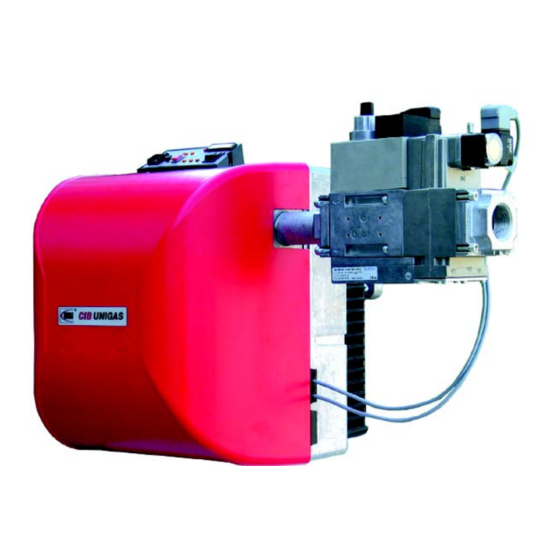
CIB UNIGAS - M039155CD PART I: INSTALLATION GENERAL FEATURES Burners of this series are provided with a removable cover made of ABS, a heat and crash proof plastic material. The design of the shi- fitng flange assures a n efficient tightness and room savin g. The i nspection glass al lows checking the flame d uring operation. All the mechanical components are mopunted on a removable plate that makes routine maintenance operation easier. -
Page 6: How To Interpret The Burner's "Performance Curve
CIB UNIGAS - M039155CD How to interpret the burner’s “Performance curve” To check if the burner is suitable for the boiler to which it must be installled, the following parameters are needed: furnace input, in kW or kcal/h (kW = kcal/h / 860);... -
Page 7: Specifications
CIB UNIGAS - M039155CD Burner model identification Burners are identified by burner type and model. Burner model identification is described as follows. Type NG200 Model NG - Natural gas burner LG - L.P.G. burner (1) BURNER TYPE NGX - Low NOx burners... - Page 8 CIB UNIGAS - M039155CD BURNERS LG140..TN..15 LG140..TN..20 LG140..TN..25 60 - 170 Output min.- max. kW L.P.G. Fuel Category 3B/P 2.3 - 6.5 Gas rate min.-max.(Stm Note2 Gas pressure min.-max.mbar 230V - 50 Hz Power supply 0.48 Total power consumption 0.18...
- Page 9 CIB UNIGAS - M039155CD BURNERS NG200..xx..20 NG200..xx..25 LG200..xx..20 LG200..xx..25 42 - 200 Output min.- max. kW Natural gas L.P.G. Fuel Category see next paragraph 4.4 - 21 1.5 - 7.7 Gas rate min.-max.(Stm Note2 Gas pressure min.-max.mbar 230V - 50 Hz Power supply 0.48...
-
Page 10: Low Nox Burners
CIB UNIGAS - M039155CD Low NOx burners BURNERS NGX120 M-.TN...20 NGX120 M-.xx...20 75 - 120 35 - 120 Output min.- max. kW Natural gas Fuel Category see next paragraph 8.0 - 12.7 3.7 - 12.7 Gas rate min.-max.(Stm Note2) Gas pressure min.-max.mbar... -
Page 11: Overall Dimensions
Overall dimensions (mm) Burner flange and boiler drilling plate Bmin. Bmax. Cmin. Cmax. Omin. Omax. Tmin. NG120- (S) Ø101 Ø128 Ø108 NG120- (L) Ø101 Ø128 Ø108 NG140- (S) Ø101 Ø128 Ø108 NG140- (L) Ø101 Ø128 Ø108 NG140- (S) Ø101 Ø128 Ø108 NG14- (L) Ø101 Ø128... -
Page 12: Performance Curves
CIB UNIGAS - M039155CD Performance curves Natural gas burners LPG burners NG120 M-.TN... LG120 L-.TN... NG140 M-.TN... LG140 L-.TN... NG140 M-.xx... LG140 L-.xx... NG200 M-.TN... LG200 L-.TN... NG200 M-.xx... LG200 L-.xx... To get the input in kcal/h, multiply value in kW by 860. -
Page 13: Pressure/Rate In The Network Curves
CIB UNIGAS - M039155CD Pressure/rate in the network curves Natural gas Burners LPG burners NG120 M-.TN... LG120 L-.TN... Rp ½" (15) Rp ½" (15) Rp ¾" (20) Rp ¾" (20) Rp 1" (25) Gas rate Stm Gas rate Stm NG140 M-.TN... -
Page 14: Low Nox Gas Burners
CIB UNIGAS - M039155CD Low NOx gas burners Performance curves NGX120 M-.TN..NGX120 M-.AB... NGX200 M-.TN... NGX200 M-.xx... To get the input in kcal/h, multiply value in kW by 860. Data are referred to standard conditions: atmospheric pressure at 1013mbar, ambient temperature at 15°C. -
Page 15: Mountings And Connections
CIB UNIGAS - M039155CD MOUNTINGS AND CONNECTIONS Packing The burners are dispatched in cardboard packages whose dimensions are: Standard Blast tube: 600mm x 370mm x 400mm (L x P x H) Extended Blast tube: 750mm x 370mm x 400mm (L x P x H) Packing cases of this kind are affected by humidity and are not suitable for stacking. - Page 16 CIB UNIGAS - M039155CD spacer to move the burner backwards or to design a blast tube tha suites the utilisation (please, contact the manifacturer). a) Heat output in kW b) Lenght of the flame tube in meters c) Flame tube firing intensity in MW/m d) Combustion chamber diameter (m) Fig.
-
Page 17: Installing The Gas Train
CIB UNIGAS - M039155CD Installing the gas train ATTENTION: BEFORE EXECUTING THE CONNECTIONS TO THE GAS PIPE NETWORK, BE SURE THAT THE MANUAL CUTOFF VALVES ARE CLOSED. READ CAREFULLY THE “WARNINGS” CHAPTER AT THE BEGINNING OF THIS MANUAL. The following diagram shows the gas train components which are included in the delivery and those which must be fitted by the custo- mer. - Page 18 CIB UNIGAS - M039155CD Connectors identification Burner power supply connector HIGH/LOW flame connector Single stage burner connector Double-stage burner connectors 7-pins connector 7-pins and 4-pins connectors BURNER IN LOW FLAME SIGNALLING LAMP LOW FLAME TIME METER FAN MOTOR HIGH FLAME TIME METER...
- Page 19 CIB UNIGAS - M039155CD Fully-modulating burners connectors: Fig. 7 - Probes connection by 7-pole connector BURNER LOCKOUT SIGNALLING LAMP BURNER IN LOW FLAME SIGNALLING LAMP FAN MOTOR LOW FLAME TIME METER SD-0÷10V VOLTAGE SIGNAL LINE FUSE FOR FAN MOTOR SD-0/4÷20mA...
-
Page 20: Power Supply Without Neutral
CIB UNIGAS - M039155CD Power supply without neutral If the power supply to the burner is 230V phase-phase (without the neutral wire), with the Siemens LME.. control box, between the ter- minal 2 on the board and the earth terminal, an RC Siemens RC466890660 filter must be inserted. -
Page 21: Adjusting The Air And Gas Flow Rates
CIB UNIGAS - M039155CD ADJUSTING THE AIR AND GAS FLOW RATES Combustion head pressure curves vs. the gas flow rate Curves are referred to pressure= 0mbar in the combustion head! The curves referred to the gas pressure in the combustion head, depending on the gas flow rate, are referred to the burner in the com- bustion stage (3% of residual O in the flues and CO values in the limits set by law). -
Page 22: Pressure In Combustion Head - Gas Flow Rate Curves
CIB UNIGAS - M039155CD Pressure in combustion head - gas flow rate curves Natural gas Burners NG120 Gas rate Stm NG140 NG200 Gas rate Stm Gas rate Stm L.P.G. Burners LG120 Gas rate Stm LG140 LG200 Gas rate Stm Gas rate Stm... -
Page 23: Setting Gas And Air Flow Rate
CIB UNIGAS - M039155CD Low NOx burners NGX120 NGX200 Gas rate Stm Gas rate Stm SETTING GAS AND AIR FLOW RATE To perform the adjustments, unscrew the fixing screws and remove the burner cover. ATTENTION: before starting the burner up, be sure that the manual cutoff valves are open and check that the pres- sure upstream the gas train complies the value quoted on paragraph “Technical specifications”. -
Page 24: Adjustment Procedure
CIB UNIGAS - M039155CD Adjustment procedure Before starting the burner up, drive the high flame actuator microswitch matching the low flame one (in order to let the burner ope- rates at the lowest output) to safely achieve the high flame stage. -
Page 25: Single Stage Burners
CIB UNIGAS - M039155CD Single stage burners To execute the air flow rate adjustment, proceed as follows: 11 loosen VR screw (see picture below) 12 move the ID index along the graduated slot towards + or -, in order to increase or decrease the air flow-rate, according to the requi- red combustion values;... -
Page 26: Adjusting The Gas Valves Group Fo Single-Stage And Double-Stage Burners
CIB UNIGAS - M039155CD Adjusting the gas valves group fo single-stage and double-stage burners Multibloc MB-DLE VS T(VR) The multibloc unit is a compact uni t consisting of two valves, gas p ressure switch, pres- sure stabilizer and gas filter. -
Page 27: Progressive, Fully-Modulating Burner Adjustments
CIB UNIGAS - M039155CD Progressive, fully-modulating burner adjustments Progressive and fully-modulating burners are provided with the combination control KROM-SCHROEDER CG2. Use a 2.5mm allen key to perform all the adjustments: do not use force! The pressu re switch is fa ctory-set to 14 mba r as deli vered. As fa r a s the next adj ustment see “Ad justing th e air an d gas p ressure switches”... -
Page 28: Gas Proving System Vps504 (Option)
CIB UNIGAS - M039155CD In order to avoid the governor vibrating, keep the pressure loss across the governor as small as possible by means of a low inlet pres- sure or by fitting an orifice module, an adjusting valve or the like between CG ... V and burner. Setting V to 2 or larger will dampen the vibrations. -
Page 29: Adjusting The Air And Gas Pressure Switches
CIB UNIGAS - M039155CD Adjusting the air and gas pressure switches The air pressure switch locks the control box if the air pressure is not the one requested. If it happens, unlock the burner by means of the control box unlock pushbutton, placed on the burner control panel. -
Page 30: Part Ii: Operation
CIB UNIGAS - M039155CD PART II: OPERATION LIMITATIONS OF USE THE BURNER IS AN APPLIANCE DESIGNED AND CONSTRUCTED TO OPERATE ONLY AFTER BEING CORRECTLY CON- NECTED TO A HEAT GENERATOR (E.G. BOILER, HOT AIR GENERATOR, FURNACE, ETC.), ANY OTHER USE IS TO BE CONSI- DERED IMPROPER AND THEREFORE DANGEROUS. -
Page 31: Part Iii: Maintenance
CIB UNIGAS - M039155CD PART III: MAINTENANCE At least once a year carry o ut the maintenance operations listed below. In the case of seasonal servicing, it is re commended to carry out the main tenance at the e nd of each heating season; in the case of continuous operation the maintenance is carried out every 6 months. -
Page 32: Removing The Filter In Themultibloc Dungs Mb-Dle 415 - 420
CIB UNIGAS - M039155CD Removing the filter in theMULTIBLOC DUNGS MB-DLE 415 - 420 B01 1” 1/2 - 2” Check the filter at least once a year! Change the filter if the pressure difference between pressure connection 1 and 2 (Fig. 26-Fig. 27) ∆p> 10 mbar. -
Page 33: Disassembling The Burner Plate To Service The Burner Fan
CIB UNIGAS - M039155CD Disassembling the burner plate to service the burner fan Before proceeding to maintenance/replacing operations, follow the next procedure: remove the component plate "C" by unscrewing the V1, V2, V3, V4 screws and the "F" securing pin (Fig. 30);... -
Page 34: Correct Electrodes Positioning
CIB UNIGAS - M039155CD Correct electrodes positioning To get a goo d ignition, it is necessary to observe the mea sures showed in the ne xt pictures. Be sure to fa sten the electrodes fixing screw VE, before reassembling the burner. -
Page 35: Checking The Detection Current
CIB UNIGAS - M039155CD Checking the detection current If the burner locks, execute the following inpesctions. To measure the detection signals refer to the diagrams in the following picture . If the signal is less than the value shown, check the position of the detection electrode, the electrical contacts and if necessary replace the detection electrode. -
Page 36: Troubleshooting
TROUBLESHOOTING TROUBLE CAUSE ● MAIN SWITCH OPEN ● ● LACK OF GAS MAXIMUM GAS PRESSURE SWITCH DEFECTIVE (IF ● ● PROVIDED) ● ● ● THERMOSTATS/PRESSURE SWITCHES DEFECTIVE ● OVERLOAD TRIPPED INTERVENTION ● AUXILIARIES FUSE INTERRUPTED ● ● ● ● ● CONTROL BOX FAULTY ●... -
Page 37: Spare Parts
CIB UNIGAS - M039155CD SPARE PARTS Desription Code LG/NG120 LG/NG140 LG/NG200 COVER 1011807 1011807 1011807 CONTROL BOX (one-stage regulation) 2020466 2020467 2020467 CONTROL BOX (double-stage regulation) 2020468 2020468 DETECTION ELECTRODE 2080108 2080108 2080108 GROUND ELECTRODE 2080234 2080234 2080234 INGNITION ELECTRODE... -
Page 38: Burner Exploded View
CIB UNIGAS - M039155CD SINGLE-STAGE BURNER EXPLODED VIEW DESCRIPTION HALF FLANGE HALF FLANGE BLAST TUBE COVER FIXING SCREW COVER UNLOCK BUTTON RUBBER COVER INDEX BLOCKING SCREW INDEX HOLDER BUSH SCREW SELF-BLOCKING NUT WASHER WASHER EXTENSION SCREW GAS PRESSURE INTAKE ÎELBOW... - Page 39 CIB UNIGAS - M039155CD...
- Page 40 CIB UNIGAS - M039155CD DOUBLE-STAGE BURNER EXPLODED VIEW DESCRIPTION 1.1 - 1.2 HALF FLANGE BLAST TUBE COVER FIXING SCREW COVER FIXING SCREWCOVER UNLOCK BUTTON RUBBER COVERUNLOCK BUTTON RUBBER COVER INDEX BLOCKING SCREW GAS PRESSURE INTAKE ELBOW REDUCTION VALVE GROUP VALVE GROUP FLANGE...
- Page 41 CIB UNIGAS - M039155CD...
-
Page 42: Wiring Diagrams
CIB UNIGAS - M039155CD WIRING DIAGRAMS Complete key Operation time counter first stage Operation time counter second stage Operation time counter Flame detection electrode Gas network side solenoid valve (or valves group) Burner side solenoid valve (or valves group) Fuse... -
Page 51: Appendix
APPENDIX: COMPONENTS CHARACTERISTICS Status Color code Color SIEMENS LME11/21/22 CONTROL BOX Undervoltage Yellow - red The series of equipment LME.. is used for the starup and supervisione of 1- or 2- stage gas burners. The series LME..is interchangeable with the ........ - Page 52 LME11 control sequence LME22 control sequence B´ B´ SB / R W / GP SB / R W / GP (LR) BV2 7101d02/0606 LME21 control sequence B´ SB / R W / GP Control sequence Waiting time Purge time TSA Ignition safety time Preignition time Postignition time (LR) BV2...
- Page 53 LME11 connection diagram Connection diagram Error message (alarm) Fuel valve C control RESET EK2 Remote lockout reset button Flame signal Gas pressure switch Air pressure switch Load controller K2/1 K2/2 Fan motor Control thermostat/pressurestat R / W Safety limit thermostat Limit thermostat /pressure switch Ignition transformer 7101 24 /0606...
- Page 54 CONTROL PROGRAM IN THE EVENT OF FAULT In the event of lockout, the LME.. remains locked and the red signal lamp (LED) will light up.The burner control can immediately be reset. This state If a fault occurs, all outputs will immediately be deactivated (in less is also mantained in the case fo mains failure.
- Page 56 C.I.B. UNIGAS S.p.A. Via L.Galvani, 9 - 35011 Campodarsego (PD) - ITALY Tel. +39 049 9200944 - Fax +39 049 9200945/9201269 web site: www.cibunigas.it - e-mail: cibunigas@cibunigas.it Note: Specifications and and data subject to change. Errors and omissions excepted.
Need help?
Do you have a question about the Idea Series and is the answer not in the manual?
Questions and answers