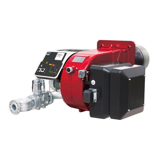
CIB UNIGAS R91A Installation, Use & Maintenance Manual
Progressive / fully modulating gas burners
Hide thumbs
Also See for R91A:
- Manual of installation - use - maintenance (48 pages) ,
- Manual of installation - use - maintenance (132 pages)

Related Manuals for CIB UNIGAS R91A


Summary of Contents for CIB UNIGAS R91A
- Page 1 R91A - R92A - R93A R512A -R515A R520A - R525A Gas burners Progressive / Fully modulating MANUAL OF INSTALLATION - USE - MAINTENANCE BURNERS - BRUCIATORI - BRULERS - BRENNER - QUEMADORES - ГОРЕЛКИ M039347CB Rel. 0.4 11/2021...
-
Page 2: General Introduction
DANGERS, WARNINGS AND NOTES OF CAUTION THIS MANUAL IS SUPPLIED AS AN INTEGRAL AND ESSENTIAL PART OF THE PRODUCT AND MUST BE DELIVERED TO THE USER. INFORMATION INCLUDED IN THIS SECTION ARE DEDICATED BOTH TO THE USER AND TO PERSONNEL FOLLOWING PRODUCT INSTALLATION AND MAINTENANCE. -
Page 3: Directives And Standards
3b) FIRING WITH GAS, LIGHT OIL OR OTHER FUELS DIRECTIVES AND STANDARDS Gas burners GENERAL European directives The burner shall be installed by qualified personnel and in compliance -Regulation 2016/426/UE (appliances burning gaseous fuels) with regulations and provisions in force; wrong installation can cause -2014/35/UE (Low Tension Directive) injuries to people and animals, or damage to property, for which the -2014/30/UE (Electromagnetic compatibility Directive) -
Page 4: Symbols Used
Burner data plate Type For the following information, please refer to Model Gas - Light oil burners Year the data plate: European Directives S.Number -Regulation 2016/426/UE (appliances burning gaseous fuels) burner type and burner model: must be Output Oil Flow -2014/35/UE (Low Tension Directive) reported in any communication with the Fuel... -
Page 5: General Features
PART I: SPECIFICATIONS PART I: SPECIFICATIONS GENERAL FEATURES Control panel with startup switch Gas valve group Electrical panel Cover Blast tube + Combustion head Flange Silencer Adjusting cam Actuator 10 Air pressure switch 11 Head adjusting ring Gas operation: the gas coming from the supply line passes through filter, gas valves and pressure regulator. This one forces the pres- sure in the utilisation limits. -
Page 6: Burner Model Identification
Burners are identified by burner type and model. Burner model identification is described as follows. Type R91A Model MD. S. BURNER TYPE R91A, R92A, R93A, R512A, R515A, R520A, R525A M - Natural gas FUEL L - LPG PR - Progressive OPERATION (Available versions) - Page 7 PART I: SPECIFICATIONS Technical Specifications BURNER TYPE R91A M-... R92A M-... R93A M-... 480 - 2670 480 - 3050 550 - 4100 Output min. - max. kW Natural gas Fuel (see next paragraph) Category Gas rate- Natural gas 51 - 283...
- Page 8 PART I: SPECIFICATIONS BURNER TYPE R512A M-... R515A M-... R520A M-... R525A M-..50 R525A M-..xx 600 - 4500 770 - 5200 1000 - 6400 2000 - 6700 2000 - 8000 Output min. - max. kW Natural gas Fuel see next paragraph Category Gas rate- Natural gas 63 - 476...
- Page 9 Burner flange Boiler recommended drilling tem- plate AA AD AN Omin Omax R91A 1495 136 35 550 100 441 1005 506 1160 435 265 295 228 450 360 464 M12 424 300 532 148 384 624 190 649 228 185...
- Page 10 Burner flange Boiler recommended drilling template 1683 1153 1590 1683 1153 1613 R512A 1683 1153 1646 1002 1683 1153 1726 1082 1683 1153 1590 1683 1153 1613 R515A 1683 1153 1646 1002 1683 1153 1726 1082 1683 1153 1590 1683 1153 1613 R520A...
- Page 11 PART I: SPECIFICATIONS How to read the burner “Performance curve” To check if the burner is suitable for the boiler to which it must be instal- Campo di lavoro bruciatori lled, the following parameters are needed: Tipo P60 Mod. M-xx.x.IT.A.0.50 - M-.xx.x.IT.A.0.65 furnace input, in kW or kcal/h (kW = kcal/h/860);...
-
Page 12: Performance Curves
PART I: SPECIFICATIONS Performance Curves R91A R92A 1200 1600 2000 2400 2800 3200 1200 1600 2000 2400 2800 R93A R512A 500 1000 1500 2000 2500 3000 3500 4000 4500 1500 2500 3500 4500 R515A R520A 1500 2500 3500 4500 5500... - Page 13 PART I: SPECIFICATIONS Pressure in the Network / gas flow rate curves (natural gas) R91A M-.. R92A M-.. R93A M-.. R512A M-.. R515A M-.. R520A M-.. R525A M-.. Rp2 R525A M-.. DN65-80-100 ATTENTION: the gas rate value is quoted on the x-axis, the related network pressure is quoted on the y-axis (pressure value in the combustion chamber is not included).
- Page 14 PART I: SPECIFICATIONS Pressure in the Network / gas flow rate curves(LPG) R91A L-.. R93A L-.. R512A L-.. R520AL-.. ATTENTION: the gas rate value is quoted on the x-axis, the related network pressure is quoted on the y-axis (pressure value in the combustion chamber is not included). To know the minimum pressure at the gas train inlet, necessary to get the requested gas rate, add the pressure value in the combustion chamber to the value read on the y-axis.
- Page 15 PART I: SPECIFICATIONS Combustion head gas pressure curves Combustion head gas pressure depends on gas flow and combustion chamber backpressure. When backpressure is subtracted, i depends only on gas flow, provided combustion is properly adjusted, flue gases residual O2 percentage complies with “Recommended combustion values”...
- Page 16 PART I: SPECIFICATIONS Pressure - rate in combustion head curves (natural gas) Curves are referred to pressure = 0 mbar in the combustion chamber! R91A M-.. R92A M-.. 100 120 140 160 180 200 220 240 260 280 300 40 60 80 100 120 140 160 180 200 220 240 260 280 300 320 340 R93A M-..
- Page 17 PART I: SPECIFICATIONS Pressure - rate in combustion head curves (LPG) Curves are referred to pressure = 0mbar in the combustion chamber! R91A L-.. R93A L-.. 100 110 120 130 140 150 160 R512A L-.. R520A L-.. 1 0 0...
-
Page 18: Transport And Storage
PART II: INSTALLATION PART II: INSTALLATION MOUNTING AND CONNECTING THE BURNER Transport and storage ATTENTION! The equipment must be installed in compliance with the regulations in force, following the manufac- turer’s instructions, by qualified personnel. All handling operations must be carried out with appropriate resources and qualified personnel ATTENTION: Use intact and correctly dimensioned hoisting equipment, conforms to the local regulations and health and safety regulations. - Page 19 PART II: INSTALLATION Fitting the burner to the boiler To install the burner into the boiler, proceed as follows: make a hole on the closing door of the combustion chamber as described on paragraph “Overall dimensions”) place the burner to the boiler: lift it up and handle it according to the procedure described on paragraph “Handling the burner”; place the 4 stud bolts (5) on boiler’s door, according to the burner drilling template described on paragraph “Overall dimensions”;...
- Page 20 PART II: INSTALLATION GAS TRAIN CONNECTIONS The diagrams show the components of the gas trai included in the delivery and which must be fitted by the installer.The diagrams are in compliance with the current laws. Gas train with valves group VGD and MBE with built-in gas pressure governor + gas leakage pressure switch (PGCP) by others supplied by burner constructor gas inlet...
- Page 21 PART II: INSTALLATION To mount the gas train, proceed as follows: In case of threaded joints: use proper seals according to the gas used- in case of flanged joints: place a gasket between the ele- ments Fasten all the items by means of screws, according to the diagrams showed, observing the mounting direction for each item NOTE: the bellows unit, the manual cutoff valve and the gaskets are not part of the standard supply MultiBloc MBE ALLA V.
- Page 22 PART II: INSTALLATION Mounting VD-R & PS-... ActuatorVD-V ActuatorVD-R M12 x 5 Pin The actuator VD-V does not need any adjustment (funzione ON-OFF) The actuator VD-R It must be combined with the PS sensor (include regolatore di pressione) VD-R + PS 1.
-
Page 23: Mounting Positions
PART II: INSTALLATION = BS SKP1. SKP2. SIEMENS VGD.. Mounting positions version with SKP2 (built-in pressure stabilizer) Siemens VGD valves with SKP actuator: The pressure adjusting range, upstream the gas valves group, changes according to the spring provided with the valve group. To replace the spring supplied with the valve group, proceed as fol- lows: - Remove the cap (T) - Page 24 PART II: INSTALLATION Integrated proving system (burners equipped with LME7x, LMV, LDU) This paragraph describes the integrated proving system operation sequence: At the beginning both the valves (EV1 and EV2) must be closed. Test space evacuating: EV2 valve (burner side) opens and keep this position for a preset time ...
-
Page 25: Electrical Connections
PART III: OPERATION PART III: OPERATION ELECTRICAL CONNECTIONS WARNING! Respect the basic safety rules. make sure of the connection to the earthing system. do not reverse the phase and neutral connections. fit a differential thermal magnet switch adequate for connection to the mains. WARNING! before executing the electrical connections, pay attention to turn the plant’s switch to OFF and be sure that the burner’s main switch is in 0 position (OFF) too. - Page 26 PART III: OPERATION A FUNDAMENTAL FACTOR IN THIS RESPECT IS THE ELECTRICAL CONNECTION TO THE GENERATOR’S CONTROL AND SAFETY UNITS (CONTROL THERMOSTAT, SAFETY, ETC.) WHICH GUARANTEES CORRECT AND SAFE FUNCTIONING OF THE BURNER. THEREFORE, ANY OPERATION OF THE APPLIANCE MUST BE PREVENTED WHICH DEPARTS FROM THE INSTALLATION OPERATIONS OR WHICH HAPPENS AFTER TOTAL OR PARTIAL TAMPERING WITH THESE (E.G.
- Page 27 PART III: OPERATION AIR FLOW AND FUEL ADJUSTMENT WARNING! During commissioning operations, do not let the burner operate with insufficient air flow (danger of formation of carbon monoxide); if this should happen, make the fuel decrease slowly until the normal combustion values are achieved.
- Page 28 PART III: OPERATION shaft the air damper closes and the air flow rate decreases. Note: once the procedure is perfomed, be sure that the blocking nut RA is fasten. Do not change the position of the air dam- per rods. 10 If necessary, adjust the combustion head position (see the dedicated paragraph).
-
Page 29: Pressure Taps
PART III: OPERATION Regulation VD-R whith PS MultiBloc MBE Setting scale is „Not“ linear! Various sensors available. Output pressure according to sensor‘s measuring range. Increasing pressure Adjust the outlet pressure to the value specified by the burner or equipment manufacturer! While making outlet pressure adjustments, do not exceed a value that creates a hazardous condition to the burner! Decreasing pressure... - Page 30 PART III: OPERATION Calibration air and gas pressure switches The air pressure switch locks the control box if the air pressure is not the one requested. If it happens, unlock the burner by means of the control box unlock pushbutton, placed on the bur- ner control panel.
- Page 31 PART III: OPERATION Adjusting the combustion head Attention! if it is necessary to change the head position, repeat the air and fuel adjustments described above. Only if necessary, change the combusiton head position: to let the burner operate at a lower output, loose the VB screw and move pro- gressively back the combustion head towards the MIN position, by turning clockwise the VRT ring nut.
- Page 32 PART III: OPERATION opened holes closed holes The adjusting plate correct position must be regulated in the plant during the commissioning. The factory setting depends on the type of fuel for which the burner is designed: For natural gas burners, plate holes are fully opened ...
-
Page 33: Routine Maintenance
PART IV: MAINTENANCE PART IV: MAINTENANCE At least once a year carry out the maintenance operations listed below. In the case of seasonal servicing, it is recommended to carry out the maintenance at the end of each heating season; in the case of continuous operation the maintenance is carried out every 6 months. - Page 34 PART IV: MAINTENANCE Head adjusting screw Threaded rod Fixing screw Gas manifold ”O” ring Cover Baffle...
-
Page 35: Electrodes Adjustment
PART IV: MAINTENANCE Electrodes Adjustment Important Note: Check the ignition and detection electrodes after removing/adjusting the combustion head. ATTENTION: avoid the ignition and detection electrodes to contact metallic parts (blast tube, head, etc.), other- wise the boiler’s operation would be compromised. Check the electrodes position after any intervention on the combustion head. -
Page 36: Seasonal Stop
PART IV: MAINTENANCE replace the combustion head. ATTENTION: avoid the electrode to get in touch with metallic parts (blast tube, head, etc.), otherwise the boiler operation would be compromised. Check the electrode position after any intervention on the combustion head. Checking the detection current with electrode (natural gas) To check the detection signal follow the scheme in the picture below. -
Page 37: Wiring Diagrams
PART IV: MAINTENANCE disconnect the power mains close the fuel valve of the supply line Burner disposal In case of disposal, follow the instructions according to the laws in force in your country about the “Disposal of materials”. WIRING DIAGRAMS Refer to the attached wiring diagrams. - Page 38 PART IV: MAINTENANCE TROUBLESHOOTNG GUIDE Gas operation * No electric power supply * Restore power supply * Main switch open * Close switch * Thermostats open * Check set points and thermostat connections * Bad thermostat set point or broken thermostat * Reset or replace the thermostat * No gas pressure * Restore gas pressure...
- Page 40 C.I.B. UNIGAS S.p.A. Via L.Galvani, 9 - 35011 Campodarsego (PD) - ITALY Tel. +39 049 9200944 - Fax +39 049 9200945/9201269 web site: www.cibunigas.it - e-mail: cibunigas@cibunigas.it Note: specifications and data subject to change. Errors and omissions excepted.
- Page 41 CIB UNIGAS 600V CONTROLLER USER’S MANUAL COD. M12925CA Rel 1.2 08/2014 SOFTWARE VERSION 1.0x code 80379 / Edition 01 - 06/2012 1 • INSTALLATION 2 • TECHNICAL SPECIFICATIONS Display 2x4 digit green, high display 10 and 7mm Keys 4 of mechanical type (Man/Aut, INC, DEC, F) •...
- Page 42 3 • DESCRIPTION OF FACEPLATE Function indicators Indication of output states Indicates modes of operation OUT 1 (AL1); OUT 2 (OPEN); OUT 3 (CLOSED) MAN/AUTO = OFF (automatic control) ON (manual control) PV Display: Indication of process variable Error Indication: LO, HI, Sbr, Err PRE-HEATING = ON (running) LO= the value of process variable is <...
-
Page 43: Programming And Configuration
5 • “EASY” PROGRAMMING and CONFIGURATION S4 Jumper THE EASY CONFIGURATION (Pro=0...12) IS SUITABLE FOR (CPU) VERSIONS WITH AL1/OPEN/CLOSED LEVEL 1 MENU P.V. / S.V. Process variable P.V. / S.V. (PV display) Work Setpoint (SV display) or control output value with controller in manual Password Local Setpoint... - Page 44 • InFo Display Information display Software version 0 No Error Self diagnostic 1 Lo error code 2 Hi 3 ERR 4 SBR OUTPUT 2 OUTPUT 3 SERIAL COMMUNICATION 0 = None 0 = None 0 = None +8 error OUT2 card recognition 1 = Relay 1 = Relay +16 error OUT3 card recognition...
- Page 45 • InP Input settings S, R range 0...1750°C; error < 0.2% f.s. (t > 300°C) / for other sp. r 0 default (remote setpoint present) Def. remote setpoint range; error < 0.5% f.s. error < 0.2% f.s. (t > -150°C) range 44...1800°C;...
- Page 46 • Out Output settings Select a1. r reference signal for alarm1 AL.1.r AL.x.r Variable to be compared PV (process variable) AL.1.t AL.x.t Direct (high limit) Absolute or Normal 2/3 for a1. t Inverse (low limit) relative to Symmetrical alarm 1 active setpoint (window) direct...
- Page 47 • Prot Protection code Prot Display Modification SP, Hy.P, Hy.n, AL.2, AL.3, PoS, OuP, INF SP, Hy.P , Hy.n, AL.2, AL.3, PoS SP, Hy.P, Hy.n, AL.2, AL.3, PoS, OuP, INF SP, OuP, INF + 4 to disable InP, Out + 8 to disable CFG + 16 to disable SW “power-up - power down”...
- Page 48 ld. 1 Function of LEDs Val. Function none MAN/AUTO controller ld. 2 HOLD Selftuning enabled Autotuning enabled ld. 3 Error present Softstart running Set point gradient running Pre-heating running + 16 LED flashes if active • Lin Custom linearization for main input Step 0 beginning Display limits s.
- Page 49 7 • CONSENT FOR BURNER AL1 Obtain burner consent by configuring alarm 1 as inverse deviation with positive hysteresis Hy.P and negative hysteresis Hy.n 8 • PRE-HEATING FUNCTION Enable the pre-heating function by setting parameters GS.0, Ht.0, GS.1 other than zero. It consists of three phases that are activated sequentially at firing: - Ramp 0 phase Enabled by setting GS.0 >...
- Page 50 9 • ADJUSTMENT WITH MOTORIZED VALVE In an adjustment process the adjustment valve has the function of varying fuel delivery (frequently corresponding to the thermal energy introduced into the process) in relation to the signal coming from the controller. For this purpose it is provided with an actuator able to modify its opening value, overcoming the resistances produced by the fluid passing inside it.
-
Page 51: Control Actions
Valve control modes With the controller in manual, the setting of parameter At.y ≥ 8 allows direct control of the valve open and close commands through the keyboard Increments and Decrements on the front seats. V0 - for floating valve without potentiometer Model V0 have similar behaviour: every manoeuvre request greater than the minimum impulse t.Lo is sent to the actuator by means of the OPEN/CLOSE relays;... -
Page 52: Manual Tuning
11 • MANUAL TUNING A) Enter the setpoint at its working value. B) Set the proportional band at 0.1% (with on-off type setting). C) Switch to automatic and observe the behavior of the variable. It will be similar to that in the figure: Process D) The PID parameters are calculated s follows: Proportional band Variable... - Page 53 15 • ACCESSORIES • Interface for instrument configuration Kit for PC via the USB port (Windows environment) for GEFRAN instruments configuration: KIT PC USB / RS485 o TTL Lets you read or write all of the parameters • A single software for all models •...
- Page 55 21/06/2012 rev. 0 Set-up for 600V RRR0-1-T73 regulator Set up for temperature probe Pt100 (ex Siemens QAE2120 130°C max.) The regulator comes out of the factory preset with the corresponding values of the Siemens RWF40.000 and RWF50.2x Verify wiring of the sensor Regulation of the set-point = 80 It can be modified by using arrows "up"...
-
Page 56: Manual Operation
A1.r … A1.t 3 (operating mode AL1 =inverse-relative-normal) … rL.1 2 (AL1) rL.2 18 (open) rL.3 19 (close) A.ty 9 (type of servocontrol command) Ac.t 12 (servocontrol running time: SQN72.4…/STA12..=12; SQM40.265=30) t_Lo t_Hi t.on t.oF dE.b 0,1 (dead zone in % of end scale) 99 then push and keep pushed F until visualization of Hrd …... - Page 57 Set up for temperature probe Pt100 for high temperature (350°C max.) Verify wiring of the sensor Regulation of the set-point = 80 It can be modified by using arrows "up" and "down". By pushing F you go to parameters: Hy.P 10 (hysteresis positive for output 1 terminals 21-22 (ex Q13-Q14) Hy.n -5 (hysteresis negative for output 1 terminals 21-22 (ex Q13-Q14)
- Page 58 A1.r … A1.t 3 (mode AL1 =inverse-relative-normal) … rL.1 2 (AL1) rL.2 18 (open) rL.3 19 (close) A.ty 9 (type of servocontrol command) Ac.t 12 (servocontrol running time: SQN72.4…/STA12..=12; SQM40.265=30) t_Lo t_Hi t.on t.oF dE.b 0,1 (dead zone in % of end scale) 99 then push and keep pushed F until visualization of Hrd …...
- Page 59 Set up for pressure transmitter 2 wires signal 4÷20mA With pressure transmitters first we need to enable their power supply: remove the part as shown below, then, on the CPU unit, move the bridge from Pt100 to +Vt IN/OUT cards Signal selection on terminal 3 Verify wiring of the sensor...
- Page 60 …. 44 (4÷20mA) … dP_S 2 (decimals num.) Transmitter 1,6bar 3bar 10bar 16bar 25bar 40bar Lo.S 0,00 0,00 0,00 0,00 0,00 0,00 min. sensor scale Hi.S 1,60 3,00 10,00 16,00 25,00 40,00 max sensor scale offset of input correction Lo.L 0,00 0,00 0,00...
- Page 61 Set -up for thermocouples type Verify wiring of the sensor Regulation of the set-point = 80 It can be modified by using arrows "up" and "down". By pushing F you go to parameters: Hy.P 10 (hysteresis positive for output 1 terminals 21-22 (ex Q13-Q14) Hy.n -5 (hysteresis negative for output 1 terminals 21-22 (ex Q13-Q14) Keep pushing F until you see PASS, release F and through the arrows set 99, push F and visualize Pro...
- Page 62 A1.r … A1.t 3 (mode AL1 =inverse-relative-normal) … rL.1 2 (AL1) rL.2 18 (open) rL.3 19 (close) A.ty 9 (type of servocontrol command) Ac.t 12 (servocontrol running time: SQN72.4…/STA12..=12; SQM40.265=30) t_Lo t_Hi t.on t.oF dE.b 0,1 (dead zone in % of end scale) 99 then push and keep pushed F until visualization of Hrd …...
- Page 65 MANUAL FOR OPERATION AND CALIBRATION MODULATOR SIEMENS RWF 40…. M12905CH Rev. 07 11/09...
-
Page 66: Instrument Mounting
INSTRUMENT MOUNTING Mount the instrument using the relevant mounts as illustrated in the figure. To wire the instrument and sensors, follow the instructions given on the burner's wiring diagrams. INSTRUMENT FRONTAL PANEL Current value or value of parameter (red) Setpoint or name of parameter (green) Manual operation... -
Page 67: Instrument Settings
INSTRUMENT SETTINGS The instrument comes with a number of factory settings that are good for 90% of cases. However, you can set or edit parame- ters proceeding as follows 1. Setting or editing of setpoint value With the burner switched off (thermostat/pressure switch series contacts open, i.e. terminals 3-4 open), press the PGM key, holding it down for less than 2 sec.. - Page 68 SCL2:lower limit for analogue input 2 (same as SCL but for input 2 - factory setting 0); SCH2:upper limit for analogue input 2 (same as SCH but for input 2 - factory setting 100); SPL: lower setpoint limit (same as SCL but for setpoint - factory setting 0); SPH: upper setpoint limit (same as SCH but for setpoint - factory setting 100);...
- Page 69 TABLE 1 - "PID" PARAMETERS AND RELEVANT FACTORY SETTINGS Parameter Display Values range Factory setting Remarks Limit value for auxiliary from -1999 to 9999 Do not alter contact (*) digit Auxiliary contact switching HYST from 0 to 999.9 digit Do not alter differential (*) from 0.1 to 9999 Proportional band (*)
- Page 70 TABLE 2 - INPUTS CONFIGURATION C111 Red display Analog input 1 1^ digit 2^ digit 3^ digit 4^ digit Pt100 3 wires Pt100 22 wires Ni100 3 wires Ni100 22 wires Pt1000 3 wires Pt 1000 22 wires Ni1000 3 wires DIN 43760 Ni1000 22 wires DIN 43760 Ni1000 3 wires Siemens Ni1000 22 wires Siemens...
- Page 71 TABLE 3 - CONFIGURATION C112 Red display 1^ digit 2^ digit 3^ digit 4^ digit Auxiliary limit switch K6 none lk1 function for input 1 lk2 function for input 1 lk3 function for input 1 lk4 function for input 1 lk5 function for input 1 lk6 function for input1 lk7 function for input 1...
- Page 72 TABLE 4 - CONFIGURATION C113 Red display 1^ digit 2^ digit 3^ digit 4^ digit Instrument addresses (for RWF 40.003 only address 0 address 1 address... address 99 Unit of measurement and decimal place °C without decimal °C and 1 decimal °F without decimal °F and 1 decimal Activation of “K6”...
- Page 73 TABLE 5 - SUMMARY OF STANDARD PARAMETER SETTINGS PARAMETERS TO BE EDITED SENSORS/PROBES C111 C113 HYS1 (*) HYS3 (*) Pb. 1 SP1 (*) Siemens QAE2120.010 9030 0110 80°C Siemens QAM2120.040 9030 0110 -2,5 40°C Pt1000 (130°C max.) 5030 0110 80°C Pt1000 (350°C max.) 5030 0110...
- Page 74 Probe electric connection : With 7 pins connector version With terminals version TRASDUCER PASSIVE TRASDUCER PASSIVE CONNECTION ONLY CONNECTION ONLY TRASDUCER PASSIVE TRASDUCER PASSIVE CONNECTION ONLY CONNECTION ONLY...
- Page 75 With external setpoint C111 configuration code = X1X1 With setpoint modified by independent management system C111 configuration code = X9XX SCH2= 0.5x (SPH - SPL) SCL2= -0.5 x (SPH - SPL) Example: SPH= max. 130° C SPL= min. 30° C SCH2= 0.5 x (130 - 30) = 50 SCL2= -0.5 x (130 - 30) = -50...
- Page 76 APPENDIX: PROBES CONNECTION To assure the utmost comfort, the control system needs reliable information, which can be obtained provided the sensors have been installed correctly. Sensors measure and transmit all variations encountered at their location. Measurement is taken based on design features (time constant) and according to specific operating conditions. With wiring run in raceways, the sheath (or pipe) containing the wires must be plugged at the sensor's terminal board so that currents of air cannot affect the sensor's measurements Ambient probes (or ambient thermostats)
- Page 77 Duct or pipe sensors Installing pressure sensors Installing temperature sensors A - installation on ducts carrying fluids at max. temperature For measuring outlet air: 80°C B - installation on ducts at temperature over 80°C and for refri- after delivery fan or gerants after coil to be controlled, at a distance of at least 0,5 m C - installation on ducts at high temperatures:...
- Page 78 Immersion or strap-on sensors Immersion probes mounting Sensors must be installed on the stretch of pipe in which fluid circulates all the time. The rigid stem (sensing element doing the measuring) must be inserted by at least 75mm and must face the direction of flow.
- Page 79 Duct pressure switches and sensors Installing differential pressure probes for air Basic principles Measuring static pressure (i.e. pressure exerted by air on pipe walls) A - Control a filter (clogging) Measuring dinamic pressure B - Control a fan (upstream/downstream) kg/m3, specific weight of air m/s, air speed 9.81 m/s2, gravity acceleration mm C.A., dynamic pressure...
- Page 80 Spare parts Description Code Modulator RWF40.000 2570112 Adapting frame Siemens ARG40 from RWF32.. to RWF40.. 2570113 Temperature probe Siemens QAE2120.010A (30÷130°C) 2560101 Temperature probe Siemens QAM2120.040 (-15÷+50°C) 2560135 Thermoresistor Pt1000 ø = 6mm L = 100mm (30÷130°C) 2560188 Thermoresistor Pt1000 ø = 10mm L = 200mm (0÷350°C) 2560103 Pressure probe Siemens QBE2..
- Page 81 RWF50.2x & RWF50.3x User manual M12922CB Rel.1.0 07/2012...
-
Page 82: Device Installation
DEVICE INSTALLATION Install the device using the relevant tools as shown in the figure. To wire the device and sensors, follow the instructions on the burner wiring diagram. -
Page 83: Front Panel
FRONT PANEL NAVIGATION MENU Parameter level Basic display User Level - Opr SP1 or SP2 (editable) dSP readable and editable through bin1 = 2 InP1 or y (only display) Parameter Level - PArA HYS1 , HYS2 , HYS3 Pb1, dt, rt, db, tt Next parameter Main navigation... - Page 84 RWF5 is preset good for 90% of applications. However, you can set or edit parameters as follow: Set-point: set or modification: When the burner is in stand-by, (safety loop open, that is terminals 3-4/T1-T2 on the 7 pole plug open) push the Enter button: on the lower display (green) Opr appears;...
- Page 85 Setting the kind of sensor to be connected to the device: push the Enter button: on the lower display (green) Opr appears. Using the up and down arrows find ConF. Push Enter to confirm. Now on the green display the group InP appears. Push Enter and InP1 is displaied. Enter to confirm. ...
- Page 86 ConF > Cntr Parameter Value Description CtYP 1 = 3-position controller (open-stop-close only RWF50.2) controller type 2 = continuative action controller (only RWF50.3) CACt 1 = heating controller control action 0 = cooling controller least value of the set-point limitation prevents entry of values outside the defined set-point range -1999..0..+9999 range...
- Page 87 ConF > OutP (parameter under group only for RWF50.3) Parameter Value Description FnCt 1 = analog input 1 doubling with possibility to convert tipo di controllo (depending on par SiGn) 4 = modulation controller SiGn physical output signal (terminals A+, A-) type of output signal 0 = 0÷20mA 1 = 4÷20mA...
- Page 88 Manual control : in order to manual change the burner load, while firing keep pushing the ESC button for more than 5 s; on the lower green display Hand appears. using the UP and DOWN arrows, the load varies. ...
-
Page 89: Electric Connection
Electric connection : With 7 pins connector version With terminals version Matches terminals between RWF50.2 and RWF40.0x0... - Page 90 Parameters summarising for RWF50.2x: Conf Conf Navigation menù Inp1 Cntr diSP PArA Types of probe SEn1 OFF1 SCL1 SCH1 Unit dECP Pb. 1 dt HYS1 (*) HYS3 (*) SP1 (*) Siemens QAE2120… needless needless 80 350 (#) 80 °C Siemens QAM2120.. needless needless 80 350 (#)
- Page 91 APPENDIX: PROBES CONNECTION To assure the utmost comfort, the control system needs reliable information, which can be obtained provided the sensors have been installed correctly. Sensors measure and transmit all variations encountered at their location. Measurement is taken based on design features (time constant) and according to specific operating conditions.With wiring run in raceways, the sheath (or pipe) containing the wires must be plugged at the sensor's terminal board so that currents of air cannot affect the sensor's measurements.
- Page 92 Duct or pipe sensors Installing pressure sensors A - installation on ducts carrying fluids at max. temperature 80°C Installing temperature sensors For measuring outlet air: B - installation on ducts at temperature over 80°C and for refrigerants after delivery fan or C - installation on ducts at high temperatures: ...
- Page 93 Immersion or strap-on sensors Immersion probes installation Sensors must be installed on the stretch of pipe in which fluid circulates all the time. The rigid stem (sensing element doing the measuring) must be inserted by at least 75mm and must face the direction of flow. Recommended locations: on a bend or on a straight stretch of pipe but tilted by 45°...
- Page 94 Duct pressure switches and sensors Installing differential pressure probes for air Basic principles Measuring static pressure(i.e. pressure exerted by air on pipe walls) A - Control a filter (clogging) Measuring dinamic pressure B - Control a fan (upstream/downstream) Kg/m , specific weight of air m/s, air speed 9.81 m/s gravity acceleration...
-
Page 95: Spare Parts
Spare parts Description Code Modulator RWF50.2 (uscita a 3 punti - apri, fermo, chiudi) 2570148 2570149 Modulator RWF50.3 (uscita continua 0÷20mA, 4÷20mA, 0÷10V) Temperature probe Siemens QAE2120.010A (30÷130°C) 2560101 2560135 Temperature probe Siemens QAM2120.040 (-15÷+50°C) 2560188 Thermoresistor Pt1000 ø6mm L100mm (30÷130°C) Thermoresistor Pt1000 ø10mm L200mm (0÷350°C) 2560103 2560145... - Page 96 Note: Specifications and data subject to change. Errors and omissions excepted.
- Page 97 KM3 Modulator USER MANUAL M12927CA Rel.1.0 10/2020...
- Page 98 M12927CA MOUNTING...
-
Page 99: Outp Ut Leds
M12927CA DISPLAY Y AND KEY onsent to the burner is rned off OUTP UT LEDs ON (o out1) - Consen nt to the burne ▲ - (o out2) Output i ncrease ▼ - (o out3) Output d decrease ● - (ou ut4) Modulato r is powered o perator Mode... -
Page 100: Probe Connection
M12927CA CONNECTIONS DIAGRAM Probe connection: • PT1000/NTC/PTC: between terminal 3 and 2 • PT 100: between terminal 3 and 2 with terminal 1 • Passive pressure probe 0/4-20 mA: between terminal 4 ( + ) e 1 ( - ) Note: out4 must be activated ( IO4F must be setted to ON ) •... -
Page 101: Operation Example
M12927CA SETPOINT AND HYSTERESIS CONFIGURATION (SP, AL1, HAL1 parameters) Push the button to enter into the setpoint configuration: SP setpoint value change: increase decrease 2480 Confirm / Next AL1 parameter value change: increase decrease Confirm / Next HAL1 HAL1 parameter value change: increase decrease Confirm / Next Back to the first parameter To return to normal mode, press the key for 3 seconds or wait the 10s timeout... - Page 102 M12927CA LIMITED ACCESS LEVEL Proceed as follows to change some parameters that are not visible in standard user mode: Press the key for Password = 20 3 seconds Access to parameter: Increase the displayed value Decrease the displayed value Confirm and go to next parameter Param Description...
- Page 103 M12927CA...
-
Page 104: Configuration Parameters
M12927CA CONFIGURATION How to access configuration level The configuration parameters are collected in various groups. Every group defines all parameters related with a specific function (e.g.: control, alarms, output functions). Push the button for more than 5 seconds. The upper display will show PASS while the lower display will show 0. - Page 105 M12927CA Safety output value -100... 100 io4.F I/O4 function selection on = Out4 will be ever ON (used as a transmitter power supply) ,out4 = Uscita 4 (Used as digital output 4), dG2c = Digital input 2 for contact closure, dG2U = Digital input 2 driven by 12... 24 diF1 Digital input 1 function oFF = Not used,...
- Page 106 M12927CA windows SE.br = Sensor Break LodE = Deviation low alarm (relative) HidE = Deviation high alarm (relative) LHdo = Relative band alarm in alarm out of the band LHdi = Relative band alarm in alarm inside the band Alarm 1 function 0...
- Page 107 M12927CA AL3 Group - alarm 3 parameters Param Description Values Liv N° Default AL3t Alarm 3 type nonE = Alarm not used nonE LoAb = Absolute low alarm HiAb = Absolute high alarm LHAo = Windows alarm in alarm outside the windows LHAI = Windows alarm in alarm inside the windows...
- Page 108 M12927CA SELF Self tuning enabling no = The instrument does not perform the self- tuning YES = The instrument is performing the self- tuning Proportional band 1... 9999 (E.U.) page 7 Integral time 0 (oFF) ... 9999 (s) page 7 Derivative time 0 (oFF) ...
- Page 109 M12927CA AAc = Alarm reset ASi = Alarm acknowledge chSP = Sequential set point selection St.by = Stand by mode. The first press puts the instrument in stand by mode while a second one puts the instrument in Auto mode. Str.t = Timer run/hold/reset P.run = Program run P.rES = Program reset...
- Page 110 M12927CA con Group - Consumption parameters Param Description Values N° Default Co.tY Count type oFF = Not used 1 = Instantaneous power (kW) 2 = Power consumption (kW/h) 3 = Energy used during program execution. This measure starts from zero when a program runs end stops at the end of the program.
-
Page 111: Automatic Mode
M12927CA OPERATIVE MODES When the instrument is powered, it starts immediately to work according to the parameters values loaded in its memory. The instrument behaviour and its performance are governed by the value of the stored parameters. At power ON the instrument can start in one of the following mode depending on its configuration: Automatic Mode In Automatic mode the instrument drives automatically the control output according to the parameter value set and the set point/measured value. -
Page 112: Manual Mode
M12927CA Direct set point modification This function allows to modify rapidly the set point value selected by [83] A.SP (selection of the active Set point) or to the set point of the segment group (of the programmer) currently in progress. Push button. -
Page 113: List Of Possible Errors
M12927CA ERROR MESSAGES The upper display shows the OVER-RANGE and UNDERRANGE conditions with the following indications: Over-range: Under-range The sensor break will be signalled as an out of range: Note: When an over-range or an under-range is detected, the alarms operate as in presence of the maximum or the minimum measurable value respectively. - Page 114 RWF55.5X & RWF55.6X User manual M12926CA Rel.0.1 10/2015...
- Page 115 DEVICE INSTALLATION Fixing system Drilling dimensions:...
- Page 116 FRONT PANEL Burner release Controlling element CLOSED/stage 1 Controlling element OPEN/stage 2 Operating mode 2-stage Actual value display (red) and parameter value USB led Comunication via interface Operating mode 2-stage Thermal shock protection Alarm function Decrease value Increase value ESC button Enter button...
- Page 117 NAVIGATION MENU User Level - Opr Parameter level SP1 or SP2 (editable) dSP readable and editable through bin1 = 2 InP1 or y (only display) Basic display Parameter level - PArA Pb1, dt, rt, db, tt Heating controllerHYS1 , HYS2 , HYS3 Cooling controller HYS4 , HYS5 , HYS6...
- Page 118 PID parameters set and modifications (PArA): Push Enter button, on the green display Opr appears; using the down arrow, scroll until group PArA is reached and push Enter. On the green display Pb1 e appears and on the red one the set parameter. Push is sequence the down or up arrow the menu is scrolled. Push Enter to select and the arrows to choose the desired value.
- Page 119 Setting the kind of sensor to be connected to the device: Push the Enter button: on the lower display (green) Opr appears. Using the up and down arrows find ConF. Push Enter to confirm. Now on the green display the group InP appears. Push Enter and InP1 is displaied. Enter to confirm.You are inside InP1; the green display shows Sen1 (sensor type), while the red display shows the chosen sensor code Push Enter to enter the Sen1 parameter, then choose the desired sensor using the arrows.
- Page 120 ConF > InP >InP2 Input 2 : this input can be used to specify an external setpoint or carry out setpoint shifting Parameter Value Description no function FnC2 external setpoint (display SPE) setpoint shifting (display dSP) angular positioning feedback SEn2 0 ÷...
- Page 121 ConF > Cntr Here, the type of controller, operating action, setpoint limits and presettings for self-optimization are selected Parameter Value Description CtYP 3-position controller (open-stop-close) ontroller type continuative action controller (0 ÷10V 4 ÷ 20mA) heating controller CACt control action cooling controller minimum set-point scale -1999..0..+9999...
- Page 122 Alarm functionAF The alarm function can be used to monitor the analog inputs. If the limit value is exceeded, multifunctional relay K6 (terminals 6N and 6P) is activated (depending on the switching characteristic) The alarm function can have different switching functions (lk1 to lk8) and can be set to a deviation from the active setpoint or to a fixed limit value Limit value AL relative to setpoint (x) Fixed limit value AL...
-
Page 123: Switched-Off
ConF > AF Parameter Value Description FnCt Without function type of control monitored input Ik1 = InP1 monitored input Ik2 = InP1 monitored input Ik3 = InP1 monitored input Ik4 = InP1 monitored input Ik5 = InP1 monitored input Ik6 = InP1 monitored input Ik7 =... - Page 124 ConF > binF This setting decides on the use of the binary inputsD1, D2, DG Parameter Value Description without function bin1 binary imput terminals set-point changeover (SP1 / SP2) – D1) set-point shift (Opr > dSP parameter = value of set-point modify) 2 = l input alarm changeover of operating mode...
- Page 125 ConF > IntF The controller can be integrated into a data network using an optional RS-485 (terminals R+ and R-) interface or an optional Profibus DP interface(only modelRWF55.6x terminalsC1-C2-C3-C4) Parameter Value Description bdrt 0 = 4800 baud baudrate 1 = 9600 baud 2 = 19200 baud 3 = 38400 baud Address in the data network...
- Page 126 Display of software version : The software version is shown by pushing Enter + UP arrow on the upper display Weather-compensated setpoint shifting(climatic regulation): The RWF55 can be configured so that weather-compensated setpoint shifting is activated when an LG-Ni1000 outside sensor or a Pt1000 is connected (see parameter InP3).
- Page 127 Modbus interface The tables that follow in this chapter specify the addresses of the readable and writable words that the customer is able to access. The customer may read and/or write the values using SCADA programs, PLCs, or similar. The entries under Access have the following meanings: R/O Read Only, value can only be read R/W Read/Write, value can be read and written The number of characters specified under Data type in the case of character strings includes the final \0.
- Page 128 Configuration level Address Access Data type Signal reference Parameter 0x3426 Float SCL1 Start of display input 1 0x3428 Float SCH1 End of display input 1 0x3432 Float SCL2 Start value input 2 0x3434 Float SCH2 End value input 2 0x3486 Float Start of setpoint limitation 0x3488...
- Page 129 Dati dell’apparecchio Address Access Data type Signal reference Parameter 0x8000 Char12 Software version 0x8006 Char14 VdN number Stato dell’apparecchio Address Access Data type Signal reference Parameter 0x0200 Word Outputs and states Bit 0 Output 1 Bit 1 Output 3 Bit 2 Output 2 Bit 3 Output 4...
-
Page 130: Electric Connections
Electric connections : With 7 pins connector version With terminals version Corrispondences bornes entre RWF55.5x y RWF40.0x0Matches terminals betweenRWF55.5x and RWF40.0x0... - Page 131 Parameters summarising for RWF55.xx : ConF ConF Navigation menù Inp1 Cntr diSP PArA Types of probe SEn1 OFF1 Unit dECP Pb. 1 HYS1 (*) HYS3 (*) SP1 (*) ...
- Page 132 APPENDIX: PROBES CONNECTION To assure the utmost comfort, the control system needs reliable information, which can be obtained provided the sensors have been installed correctly. Sensors measure and transmit all variations encountered at their location. Measurement is taken based on design features (time constant) and according to specific operating conditions.With wiring run in raceways, the sheath (or pipe) containing the wires must be plugged at the sensor's terminal board so that currents of air cannot affect the sensor's measurements.
- Page 133 Duct or pipe sensors Installing pressure sensors Installing temperature sensors A - installation on ducts carrying fluids at max. temperature 80°C For measuring outlet air: B - installation on ducts at temperature over 80°C and for refrigerants "after delivery fan or C - installation on ducts at high temperatures : "after coil to be controlled, at a distance of at least 0,5 m ·"increase length of siphon...
- Page 134 Immersion or strap-on sensors Immersion probes installation Sensors must be installed on the stretch of pipe in which fluid circula- tes all the time. The rigid stem (sensing element doing the measuring) must be inser- ted by at least 75mm and must face the direction of flow. Recommended locations: on a bend or on a straight stretch of pipe but tilted by 45°...
- Page 135 Duct pressure switches and sensors Installing differential pressure probes for air Basic principles Measuring static pressure(i.e. pressure exerted by air on pipe walls) A - Control a filter (clogging) Measuring dinamic pressure B - Control a fan (upstream/downstream) Legend Kg/m3, specific weight of air m/s, air speed 9.81 m/s2 gravity acceleration mm C.A., dynamic pressure...
- Page 137 Note: Specifications and data subject to change. Errors and omissions excepted.
- Page 143 GEFRAN 1600V 15-18 16...
Need help?
Do you have a question about the R91A and is the answer not in the manual?
Questions and answers