
Related Manuals for CIB UNIGAS HR1025


Summary of Contents for CIB UNIGAS HR1025
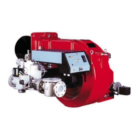
- Page 1 HR1025 HR1030 HR1040 Progressive and fully-modulating gas - light oil burners MANUAL OF INSTALLATION - USE - MAINTENANCE BURNERS - BRUCIATORI - BRULERS - BRENNER - QUEMADORES - ГОРЕЛКИ M039115CF Rel. 5.0 12/2014...
-
Page 2: General Introduction
DANGERS, WARNINGS AND NOTES OF CAUTION THIS MANUAL IS SUPPLIED AS AN INTEGRAL AND ESSENTIAL PART OF THE PRODUCT AND MUST BE DELIVERED TO THE USER. INFORMATION INCLUDED IN THIS SECTION ARE DEDICATED BOTH TO THE USER AND TO PERSONNEL FOLLOWING PRO- DUCT INSTALLATION AND MAINTENANCE. -
Page 3: Directives And Standards
DIRECTIVES AND STANDARDS do not leave the equipment exposed to weather (rain, sun, etc.) Gas burners unless expressly required to do so; European directives: do not allow children or inexperienced persons to use equipment; - Directive 2009/142/EC - Gas Appliances; The unit input cable shall not be replaced by the user. -
Page 4: Symbols Used
-EN 55014-1Electromagnetic compatibility - Requirements for household appliances, electric tools and similar apparatus. -UNI EN 676 (Gas Burners; -CEI EN 60335-1(Household and similar electrical appliances - Safety. Part 1: General requirements; - EN 50165 Electrical equipment of non-electric appliances for household and similar purposes. -
Page 5: General Features
PART I: SPECIFICATIONS PART I: SPECIFICATIONS 1.0 GENERAL FEATURES This series represents monobloc gas burners made in die-cast aluminium housing, that can burn either gas or light oil, thanks to the adjustable combustion head which allows a good performance with both fuels.They can be provided in progressive or fully-modulating version. -
Page 6: Burner Type
1.1 Burner model identification Burners are identified by burner type and model. Burner model identification is described as follows. HR1025 MD. S. Type Model HR1025 - HR1030 - HR1040 BURNER TYPE FUEL G - Light oil M - Natural gas B - Biogas... - Page 7 PART I: SPECIFICATIONS 1.2 Technical Specifications HR1025 HR1025 HR1030 HR1030 HR1040 BRUCIATORE TIPO MG..50 MG..xx MG..65 MG..xx MG..xx Output min. - max. kW 2550 - 6700 2550 - 8700 2550 - 9500 2550 - 10600 2550 - 13000 Natural gas - Light oil...
- Page 8 80 2088 377 1452 651 25 585 841 132 544 641 1544 680 21231301 822 400 450 709 660 816 M16 651 460 460 936 200 265 736 80 1092 142 322 1146 379 330 HR1025 100 2088 377 1452 651 25 585 854 145 544 641 1544 680 21391317 822 400 450 709 660 816 M16 651 460 460 842 200 265 642 80 1092 142 382 1146 379 330...
- Page 9 Fig. 2 - 3I2MG-17 v1 Hydraulic diagram - nozzle M3 ON BOARD ITEMS SUPPLIED LOOSE ITEMS oil inlet oil outlet gas inlet combustion air BY OTHERS LPG inlet BY CIB UNIGAS LPG gas - out of Cib Unigas scope of supply...
- Page 10 3I2MG17 LEGEND OIL TRAIN MAIN GAS TRAIN Filter Manual valve Flexible hose Bellows unit Pump and pressure governor Filter Electrical motor Safety valve with built in gas governor Solenoid valve Pressure switch - PGMIN Flexible hose Proving system pressure switch - PGCP Oil distributor Pressure switch - PGMAX Pressure gauge with manual valve...
- Page 11 Fig. 3 - 3I2MG-18 v1 Hydraulic diagram - nozzle type G ON BOARD ITEMS SUPPLIED LOOSE ITEMS oil inlet oil outlet gas inlet combustion air BY OTHERS LPG inlet BY CIB UNIGAS LPG gas - out of Cib Unigas scope of supply...
- Page 12 3I2MG18 LEGEND OIL TRAIN MAIN GAS TRAIN Filter Manual valve Flexible hose Bellows unit Pump and pressure governor Filter Electrical motor Safety valve with built in gas governor Solenoid valve Pressure switch - PGMIN Flexible hose Proving system pressure switch - PGCP Oil distributor Pressure switch - PGMAX Pressure gauge with manual valve...
- Page 13 PART I: SPECIFICATIONS 1.5 How to read the burner “Performance curve” To check if the burner is suitable for the boiler to which it must be instal- Campo di lavoro bruciatori lled, the following parameters are needed: Tipo P60 Mod. M-xx.x.IT.A.0.50 - M-.xx.x.IT.A.0.65 furnace input, in kW or kcal/h (kW = kcal/h / 860);...
- Page 14 PART I: SPECIFICATIONS 1.7 Performance Curves HR1025 2” HR1025 DN65 - DN80 - DN100 2000 3000 4000 5000 6000 7000 8000 9000 2000 3000 4000 5000 6000 7000 HR1030 DN65 HR1030 DN80 - DN100 HR1040 2000 3000 4000 5000 6000 7000 8000 9000 1 0000 1 1 000 1 2000 1 3000 To get the input in kcal/h, multiply value in kW by 860.
- Page 15 PART I: SPECIFICATIONS Pressure in the Network / gas flow rate curves(natural gas) HR1025 M-..1.xx Gas rate Stm HR1030 M-..65 HR1030 M-..1.xx Gas rate Stm Gas rate Stm HR1040 M-. Gas rate Stm Caution: the gas rate value is quoted on the x-axis, the related network pressure is quoted on the y-axis (pressure value in the combustion chamber is not included).
- Page 16 PART I: SPECIFICATIONS 1.8 Combustion head gas pressure curves depending on the flow rate The curves referred to the gas pressure in the combustion head, depending on the gas flow rate, are referred to the burner properly adjusted (percentage of residual O in the flues as shown in the “Recommended combustion values”...
- Page 17 PART I: SPECIFICATIONS 1.10 Pressure - rate in combustion head curves (natural gas) Curves are referred to pressure = 0mbar in the combustion chamber! HR1025 Gas rate Stm HR1030 HR1040 Gas rate Stm Gas rate Stm...
- Page 18 PART II: INSTALLATION PART II: INSTALLATION 2.0 MOUNTING AND CONNECTING THE BURNER 2.1 Packing The burners are despatched in wooden crates whose dimensions are: 2270mm x 1720mm x 1320mm (L x P x H) Packing cases of this type are affected by humidity and are not suitable for stacking. The following are placed in each packing case: burner with detached gas train;...
- Page 19 PART II: INSTALLATION 2.3 Fitting the burner to the boiler To perform the installation, proceed as follows: drill the furnace plateas decribed in paragraph (“Overall dimensions”); place the burner towards the furnace plate: lift and move the burner by means of its eyebolts placed on the top side (see”Lifting and moving the burner”);...
- Page 20 PART II: INSTALLATION 2.4 Matching the burner to the boiler The burners described in this manual have been tested with combustion chambers that comply with EN676 regulation and whose dimensions are described in the diagram . In case the burner must be coupled with boilers with a combustion chamber smaller in dia- meter or shorter than those described in the diagram, please contact the supplier, to verify that a correct matching is possible, with respect of the application involved.
- Page 21 PART II: INSTALLATION 3.0 GAS TRAIN CONNECTIONS The diagrams show the components of the gas trai included in the delivery and which must be fitted by the installer.The diagrams are in compliance with the current laws. ATTENTION: BEFORE EXECUTING THE CONNECTIONS TO THE GAS PIPE NETWORK, BE SURE THAT THE MANUAL CUTOFF VALVES ARE CLOSED.
- Page 22 PART II: INSTALLATION 3.1 Assembling the gas grain gas supply network ”direction” arrows for installation Keys 1A..1E Gasket Gas filter Gas valves group Bellows unit Manual valve Fig. 7 - Example of gas train To mount the gas train, proceed as follows: 1-a) in case of threaded joints: use proper seals according to the gas used;...
- Page 23 PART II: INSTALLATION to the burner connection to the gas supply network gas proving system connection (optional) SIEMENS VGD40.. Fig. 8 - pipe port (3) for connecting the pilot gas train to the valves group of the main gas train The procedures of installation fo the gas valves are showed in the next paragraphs, according to the gas train used: threaded gas trains with Siemens VGD20..
- Page 24 PART II: INSTALLATION SKP1. SKP2. 7631z05/0101 SIEMENS VGD..MOUNTING POSITIONS Fig. 10 Fig. 11 Fig. 9 (spring) (cap) Fig. 12 Siemens VGD valves with SKP actuator : The pressure adjusting range, upstream the gas valves group, changes according to the spring provided with the valve group. Performance range (mbar) 0 - 22 15 - 120...
- Page 25 PART II: INSTALLATION Integrated proving system (burners equipped with LME7x, LMV, LDU) This paragraph describes the integrated proving system operation sequence: At the beginning both the valves (EV1 and EV2) must be closed. Test space evacuating: EV1 valve (burner side) opens and keep this position for a preset time (td4), in order the bring the test space to ambient pressure.Test atmospheric pressure: EV1 closes and keep this position for a preset time (test time td1).
- Page 26 PART II: INSTALLATION OIL TRAIN CONNECTIONS 4.1 Hydraulic diagrams for light oil supplying circuits Fig. 13 - Gravity circuit Fig. 14 - Ring circuit Fig. 15 - Suction circuit Manual valve Light oil filter Light oil feeding pump One way valve Flexible hoses Relief valve...
- Page 27 PART II: INSTALLATION 4.2 Installation diagram of light oil pipes PLEASE READ CAREFULLY THE “WARNINGS” CHAPTER AT THE BEGINNING OF THIS MANUAL. From tank To tank Fig. 16 - Double-pipe system The burner is supplied with filter and flexible hoses, all the parts upstream the filter and downstream the return flexible hose, must be installed by the customer.
- Page 28 PART II: INSTALLATION 4.3 About the use of fuel pumps Do not use fuel with additives to avoid the possible formation over time of compounds which may deposit between the gear teeth, thus obstructing them. After filling the tank, wait before starting the burner. This will give any suspended impurities time to deposit on the bottom of the tank, thus avoiding the possibility that they might be sucked into the pump.
-
Page 29: Electrical Connections
PART II: INSTALLATION 5.0 ELECTRICAL CONNECTIONS WARNING! Respect the basic safety rules. make sure of the connection to the earthing system. do not reverse the phase and neutral connections. fit a differential thermal magnet switch adequate for connection to the mains. - Page 30 PART III: OPERATION PART III: OPERATION WARNING: before starting the burner up, be sure that the manual cutoff valves are open and check that the pres- sure upstream the gas train complies the value quoted on paragraph “Technical specifications”. Be sure that the mains switch is closed.
- Page 31 PART III: OPERATION Fig. 17 - Burner control panel B2 B3 Keys Main switch Reset pushbutton for control box CMF switch (0=stop, 1=low flame, 2=high flame, 3=automatic) - fully modulating burners only Lock-out LED Hi-flame operation LED Lo-flame operation LED “Ignition transformer operation”...
- Page 32 PART III: OPERATION 5.3 Gas operation Check the gas feeding pressure is sufficient (signalling lamp G3 on). the gas proving system test begins; when the test is performed the proving system LED turns on. At the end of the test, the burner staring cycle begins: in case of leakage in a valve, the gas proving system stops the burner and the lamp B1 turns on.
- Page 33 PART III: OPERATION 5.5 AIR FLOW AND FUEL ADJUSTMENT WARNING! During commissioning operations, do not let the burner operate with insufficient air flow (danger of formation of carbon monoxide); if this should happen, make the fuel decrease slowly until the normal combustion values are achieved.
- Page 34 PART III: OPERATION Siemens VGD.. To adjust the air flow rate in the high flame stage, loose the RA nut and screw VRA as to get the desired air flow rate: moving the rod TR towards the air damper shaft, the air damper opens and consequently the air flow rate increases, moving it far from the shaft the air damper closes and the air flow rate decreases.
- Page 35 PART III: OPERATION 5.8 Fully-modulating burners .To adjust the fully-modulating burners, use the CMF switch on the burner control panel (see next picture), instead of the TAB thermo- stat as described on the previous paragraphs about the progressive burners. Go on adjusting the burner as described before, paying attention to use the CMF switch intead of TAB.
- Page 36 PART III: OPERATION if the maximum pressure switch is mounted upstreaam the gas valves: measure the gas pressure in the network, when flame is off; by means of the adjusting ring nut VR, set the value read, increased by the 30%. if the maximum pressure switch is mounted downstream the “gas governor-gas valves”...
- Page 37 PART III: OPERATION 6.0 Adjustment procedure for light oil operation The light oil flow rate can be adjusted choosing a by-pass nozzle that suits the boiler/utilisation output and setting the delivery and return pressure values according to the ones quoted on the table below and the diagram on Fig. 20 (as far as reading the pressure values, see next paragraphs).
- Page 38 PART III: OPERATION Pump flow rate Nozzle flow rate Fig. 19 - Bergonzo B nozzle - example with 850kg/h nozzle...
- Page 39 PART III: OPERATION Oil Flow Rate Settings Once the air and gas flow rates are adjusted, turn the burner off, switch to the oil operation (OIL, on the burner control panel). with the electrical panel open, prime the oil pump acting directly on the related CP contactor (see next picture): check the pump motor rotation and keep pressing for some seconds until the oil circuit is charged;...
- Page 40 PART III: OPERATION tion. Turn the burner off; then start it up again. If the adjustment is not correct, repeat the previous steps. Pressure gauge port Fig. 22 Fig. 23 Fig. 21 7.2 Fully-modulating burners .To adjust the fully-modulating burners, use the CMF switch on the burner control panel (see next picture), instead of the TAB thermo- stat as described on the previous paragraphs about the progressive burners.
-
Page 41: Routine Maintenance
PART IV: MAINTENANCE PART IV: MAINTENANCE At least once a year carry out the maintenance operations listed below. In the case of seasonal servicing, it is recommended to carry out the maintenance at the end of each heating season; in the case of continuous operation the maintenance is carried out every 6 months. - Page 42 PART IV: MAINTENANCE 8.2 Replacing the spring in the gas valve group To replace the spring in the gas valve group,proceed as follows: Carefully twist the protection cap 1 and the O-ring 2. remove the “set value” spring 3 from housing 4. Replace spring 3.
- Page 43 PART IV: MAINTENANCE 8.4 Adjusting the ignition electrode ATTENTION: avoid the electrode to get in touch with metallic parts (blast tube, head, etc.), otherwise the boiler operation would be compromised. Check the electrode position after any intervention on the combustion head. Fig.
- Page 44 PART IV: MAINTENANCE 8.5 Replacing the ignition electrode ATTENTION: avoid the electrode to get in touch with metallic parts (blast tube, head, etc.), otherwise the boiler operation would be compromised. Check the electrode position after any intervention on the combustion head. To replace the ignition electrode, proceed as follows: remove the burner cover disconnect the electrode (E) cable (CE);...
- Page 45 PART IV: MAINTENANCE 8.8 Seasonal stop To stop the burner in the seasonal stop, proceed as follows: turn the burner main switch to 0 (Off position) disconnect the power mains close the fuel valve of the supply line 8.9 Burner disposal In case of disposal, follow the instructions according to the laws in force in your country about the “Disposal of materials”.
-
Page 46: Troubleshooting
PART IV: MAINTENANCE 9.0 TROUBLESHOOTING 9.1 Heavy oil operation MAIN SWITCH OPEN LINE FUSE INTERVENTION MAX. PRESSURE SWITCH FAULT FAN THERMAL CUTOUT INTERVENTION AUXILIARY RELAIS FUSES INTERVENTION CONTROL BOX FAULT SERVOCONTROL FAULT SMOKEY FLAME IGNITION TRANSFORMER FAULT IGNITION ELECTRODE DIRTY OR WRONG POSITIONED DIRTY NOZZLE FUEL SOLENOID VALVE DEFECTIVE... - Page 47 9.2 Gas operation TROUBLE CAUSE MAIN SWITCH OPEN LACK OF GAS MAXIMUM GAS PRESSURE SWITCH DEFECTIVE THERMOSTATS/PRESSURE SWITCHES DEFECTIVES OVERLOAD TRIPPED INTERVENTION AUXILIARIES FUSE INTERRUPTED DEFECTIVE CONTROL BOX DEFECTIVE ACTUATOR AIR PRESSURE SWITCH FAULT OR BAD SETTING MINIMUM GAS PRESSURE SWITCH DEFECTIVE OR GAS FILTER DIRTY IGNITION TRANSFORMER FAULT IGNITION ELECTRODES BAD POSITION...
-
Page 48: Wiring Diagrams
10.0 WIRING DIAGRAMS Refer to the attached wiring diagrams. WARNING 1 - Electrical supply 230V 50Hz 1 a.c./400V 50Hz 3N a.c. 2 - Do not reverse phase with neutral 3 - Ensure burner is properly earthed... - Page 49 11.0 BURNER EXPLODED VIEW ITEM DESCRIPTION ITEM DESCRIPTION ITEM DESCRIPTION AIR INLET CONE 10.5.1 ADJUSTING BUSH 14.1 BRACKET SPACER 10.5.2 STANDARD COMPLETE OIL GUN 14.2 PUMP FLEXIBLE HOSE 10.5.2.1.1 SOLENOID VALVE 14.3 COUPLING FLEXIBLE HOSE 10.6 IGNITION CABLE 14.4 PRESSURE GOVERNOR FLEXIBLE HOSE 10.7 GAS FLEXIBLE HOSE...
- Page 50 10.5.2.1.1...
- Page 51 APPENDIX SIEMENS LFL 1.3.. CONTROL BOX consent to start-up by means of the thermostat or pressostat "R" start-up program Automatic programme in the event of interruption and indication of posi- tion when interrupted normal burner operation By default, in the event of any kind of interruption, the flow of fuel is imme- regulation stop caused by "R"...
- Page 52 Ionisation monitor Twin-tube burners (**) voltage in detector electrode Preignition time until the all clear to the pilot burner valve at normal working 330V ±10% terminal 17. test 380V ±10% First safety time (pilot flame strenght); at the end of the safety time short circuit current max.
- Page 53 Programmer diagram pre-ventilation time limit contact switch for damper OPEN position safety time block remote signal '1st safety time main relay (working network) with contacts "ar" pre-ignition time Monitor fuse 'pre-ignition time block relay with "br" contacts interval for creating current between terminals 18 and 19 fuel valve 'interval for creating current between terminals 17 and 19 reset button...
- Page 55 C.I.B. UNIGAS S.p.A. Via L.Galvani, 9 - 35011 Campodarsego (PD) - ITALY Tel. +39 049 9200944 - Fax +39 049 9200945/9201269 web site: www.cibunigas.it - e-mail: cibunigas@cibunigas.it Note: specifications and data subject to change. Errors and omissions exceptd.
Need help?
Do you have a question about the HR1025 and is the answer not in the manual?
Questions and answers