Table of Contents
Advertisement
Esie06-03
What is in this part?
This part contains the following chapters:
Chapter
1–General Outline: Altherma
2–Specifications
3–Functional Diagrams
4–Piping Diagrams
5–Switch Box Layout
6–Wiring Diagrams
7–PCB Layout
System Outline
1
4
Part 1
3
See page
1–3
1–15
4
1–21
1–27
1–33
1–39
5
1–51
1–1
Advertisement
Table of Contents
Troubleshooting

Subscribe to Our Youtube Channel
Related Manuals for Daikin Altherma EKHBH Series


Summary of Contents for Daikin Altherma EKHBH Series
- Page 1 ESIE06-03 Part 1 System Outline What is in this part? This part contains the following chapters: Chapter See page 1–General Outline: Altherma 1–3 2–Specifications 1–15 3–Functional Diagrams 1–21 4–Piping Diagrams 1–27 5–Switch Box Layout 1–33 6–Wiring Diagrams 1–39 7–PCB Layout 1–51 Part 1 –...
- Page 2 ESIE06-03 1–2 Part 1 – System Outline...
- Page 3 ESIE06-03 General Outline: Altherma Part 1 General Outline: Altherma What Is in This Chapter? Introduction This chapter contains the following information on the Altherma: Outlook and dimensions Installation and service space Componentss Physical limitations and limits of operation General outline This chapter contains the following general outlines: General outline See page...
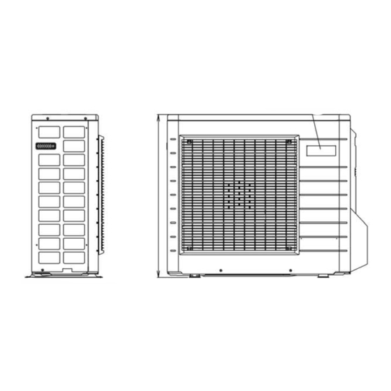
- Page 4 General Outline: Altherma ESIE06-03 ERYQ005~007AAV3N: Outlook and Dimensions Outlook and The illustration below shows the outlook and the dimensions of the unit (mm). dimensions In case of removing stop valve cover Installation and See page 1–12. service space 1–4 Part 1 – System Outline...
- Page 5 ESIE06-03 General Outline: Altherma Components The table below contains the different components of the unit. Component Brand name label Name plate Wiring inlet Terminal strip with earth terminal Outdoor air temperature thermistor Gas stop valve (φ15.9CuT) Service port Liquid stop valve (φ6.4CuT) Drain outlet (I.D.
- Page 6 General Outline: Altherma ESIE06-03 EKHBH007A***: Outlook and Dimensions Outlook and The illustration below shows the outlook and the dimensions of the unit (mm). dimensions Service door (CLOSED) 361 1’ Female BSP (OPEN) 553 1’ Male BSP Installation and See page 1–13. service space 1–6 Part 1 –...
- Page 7 ESIE06-03 General Outline: Altherma Components The table below contains the different components of the unit. Component Pump + switch for speed setting Remocon Water IN connection 1e M BSP Water OUT connection 1e M BSP Power supply intake (+ sanitary warm water tank) Drain/fill valve Air purge Expansion vessel + nipple...
-
Page 8: Ekhbx007A***: Outlook And Dimensions
General Outline: Altherma ESIE06-03 EKHBX007A***: Outlook and Dimensions Outlook and The illustration below shows the outlook and the dimensions of the unit (mm). dimensions Service door 1' Female BSP (CLOSED) 461 (OPEN) 653 1' Male BSP Dimensions wallbracket Installation and See page 1–13. - Page 9 ESIE06-03 General Outline: Altherma Components The table below contains the different components of the unit. Component Pump + switch for speed setting Remocon Water IN connection 1e M BSP Water OUT connection 1e M BSP Power supply intake (+ sanitary warm water tank) Drain/fill valve Air purge Expansion vessel + nipple...
-
Page 10: Eksww150~300V3: Outlook And Dimensions - Service Space
General Outline: Altherma ESIE06-03 EKSWW150~300V3: Outlook and Dimensions - Service Space Outlook and The illustration below shows the outlook and the dimensions of the unit (mm). dimensions - Service space 150 L 200 L 300 L 90° 90° 90° Required service space around the tank 1–10 Part 1 –... - Page 11 ESIE06-03 General Outline: Altherma Components The table below contains the different components of the unit. Component Water mains IN female 3/4’ BSP Water mains OUT female 3/4’ BSP Thermistor connection female 1/2’ BSP Flow (from Hydro-box) female 3/4’ BSP Return (to Hydro-box) female 3/4’ BSP Switchbox Clixon Connection female 1/2’...
-
Page 12: Eryq005~007Aav3N: Installation And Service Space
General Outline: Altherma ESIE06-03 ERYQ005~007AAV3N: Installation and Service Space Installing near a Where a wall or other obstacle is in the path of the outdoor unit air intake or exhaust airflow, follow wall or obstacle the installation guidelines below. For any of the installation patterns below, the wall height on the exhaust side should be 1200 mm or less. - Page 13 ESIE06-03 General Outline: Altherma EKHBH(X)007A: Installation and Service Space EKHBH The illustration below shows the minimum service space for service and ventilation. ≥ 200 ≥ 200 ≥ 400 Setup 1 ≥ 350 ≥ 200 Setup 2 EKHBX The illustration below shows the minimum service space for service and ventilation. ≥...
-
Page 14: Physical Limitations And Limits Of Operation
General Outline: Altherma ESIE06-03 Physical Limitations and Limits of Operation Distance between The illustrations and table below show the limitations. components OUTDOOR Thermostat Sanitary INDOOR tank 2 way valve 3 way valve Heat emitters Allowable heigth: indoor Total system : ≤ 20 m (outdoor unit can be above or below the hydro-box) outdoor... -
Page 15: Part 1 – System Outline
ESIE06-03 Specifications Part 1 Specifications What Is in This Chapter? Introduction This chapter contains the following information: Technical specifications Electrical specifications Altherma This chapter contains the following specifications: Specifications See page 2.2–ERYQ005~007 1–16 2.3–EKHBH and EKHBX 1–18 2.4–EKSWW150~300V3/Z2 1–20 Part 1 – System Outline 1–15... - Page 16 Specifications ESIE06-03 ERYQ005~007 Technical The table below contains the technical specifications. specifications Specification ERYQ005~007 Colour Ivory white Casing Material Polyester painted galvanised steel Packing Height 797 mm Width 960 mm Depth 390 mm Dimensions Unit Height 735 mm Width 825 mm Depth 300 mm Machine weight...
- Page 17 ESIE06-03 Specifications Specification ERYQ005~007 Refrigerant oil Type FVC50K Charged volume 0.75 l Piping connections Liquid Type Flare connection Diameter (OD) 6.35 mm Type Flare connection Diameter (OD) 15.9 mm Drain Quantity Type Socket Diameter (OD) 18 mm Piping length Min. Max.
- Page 18 Specifications ESIE06-03 EKHBH and EKHBX Technical The table below contains the technical specifications. specifications Specification EKHBH* EKHBX* EKHBH007A* EKHBH007A* EKHBH007A* EKHBX007* EKHBX007* EKHBX007* Outdoor units ERYQ005A ERYQ006A ERYQ007A ERYQ005A ERYQ006A ERYQ007A Nominal input (indoor only without electric heater) 230 W Casing Colour RAL9010...
- Page 19 ESIE06-03 Specifications Notes: The sound pressure level is measured via a microphone at a certain distance from the unit. It is a relative value, depending on the distance and acoustic environment: (2): ERYQ-models: 6.35 mm EKHB-models: 9.52 mm (flare connection) Electrical The table below contains the electrical specifications.
- Page 20 Specifications ESIE06-03 EKSWW150~300V3/Z2 Technical The table below contains the technical specifications. specifications Specification EKSWW150V3 EKSWW200V3 EKSWW300V3 EKSWW200Z2 EKSWW300Z2 Casing Colour Neutral white Material Epoxy-coated mild steel Dimensions Packing Height 950 mm 1200 mm 1650 mm 1200 mm 1650 mm Width 600 mm Depth 600 mm...
- Page 21 ESIE06-03 Functional Diagrams Part 1 Functional Diagrams What Is in This Chapter? Introduction This chapter contains the following information: Overview complete system Electrical connection diagram Pipe connection diameters. Functional This chapter contains the following functional diagrams: diagrams Functional diagram See page 3.2–Complete System 1–22 3.3–Electrical Connection Diagram...
- Page 22 Functional Diagrams ESIE06-03 Complete System 1–22 Part 1 – System Outline...
- Page 23 ESIE06-03 Functional Diagrams Components The table below contains the different components of the functional diagrams. Name Outdoor air temperature thermistor Heat exchanger Heat exchanger thermistor Propeller fan Filter Expansion valve Liquid stop valve Gas stop valve with service port Accumulator Compressor Discharge pipe thermistor 4-way valve ON: heating...
-
Page 24: Electrical Connection Diagram
Functional Diagrams ESIE06-03 Electrical Connection Diagram Standard parts Power Supply OUTDOOR UNIT For more details 3 core unit power supply: 230V + earth X1M:L-N-earth please check unit wiring diagram backup heater power supply (3/6/9kW): 400V or 230V + earth Optional power supply: X2M:1-2-3-earth booster heater power supply(3kW): 400V or 230V + earth <10m:4Gx1.5... -
Page 25: Pipe Connection Diameters
ESIE06-03 Functional Diagrams Pipe Connection Diameters Outdoor units The table below contains the refrigerant pipe connection diameters. ∅ Gas pipe (flare) ∅ Liquid pipe (flare) Model ERYQ005ABV3 15.9 mm 6.4 mm ERYQ006ABV3 ERYQ007ABV3 Hydro-box The table below contains the refrigerant pipe connection diameters. ∅... - Page 26 Functional Diagrams ESIE06-03 1–26 Part 1 – System Outline...
- Page 27 ESIE06-03 Piping Diagrams Part 1 Piping Diagrams What Is in This Chapter? Introduction This chapter contains the following information: Piping diagrams Piping diagrams This chapter contains the following piping diagrams: Functional diagram See page 4.2–ERYQ005~007 1–28 4.3–EKHBH(X) 1–30 Part 1 – System Outline 1–27...
- Page 28 Piping Diagrams ESIE06-03 ERYQ005~007 1–28 Part 1 – System Outline...
- Page 29 ESIE06-03 Piping Diagrams Components The table below contains the different components of the functional diagrams. Name Heat exchanger Heat exchanger thermistor Capillary Tube 1 Capillary Tube 2 Capillary Tube 3 Capillary Tube 4 Muffler with filter Filter Motor operated valve Liquid stop valve Field piping Gas stop valve with service port...
- Page 30 Piping Diagrams ESIE06-03 EKHBH(X) 1–30 Part 1 – System Outline...
- Page 31 ESIE06-03 Piping Diagrams Components The table below contains the different components of the functional diagrams. Name Filter Shut off valve Pressure gauge Drain valve Safety valve Expansion vessel Pump Air purge Electric heater body Flowswitch Outlet water heat-exchanger thermistor Outlet water backup heater thermistor Refrigerant liquid side thermistor Inlet water thermistor Part 1 –...
- Page 32 Piping Diagrams ESIE06-03 1–32 Part 1 – System Outline...
- Page 33 ESIE06-03 Switch Box Layout Part 1 Switch Box Layout What Is in This Chapter? Introduction This chapter shows the switch box components. Altherma This chapter contains the following switch box layouts: Switch box layout See page 5.2–ERYQ005~007 1–34 5.3–EKHBH(X)005~007A*** 1–36 5.4–EKSWW***V3/Z2 1–37 Part 1 –...
- Page 34 Switch Box Layout ESIE06-03 ERYQ005~007 The illustration below shows the outdoor switch box 1 layout: Item Description PCB1 Printed circuit board (main) Reactor coil 1–34 Part 1 – System Outline...
- Page 35 ESIE06-03 Switch Box Layout The illustration below shows the outdoor switch box 2 layout: Item Description PCB2 Printed circuit board Terminal strip: Power supply Terminal strip: Communication Part 1 – System Outline 1–35...
- Page 36 Switch Box Layout ESIE06-03 EKHBH(X)005~007A*** The illustration below shows the switch box layout: Item Description Contactor backup heater step 1 Contactor backup heater step 2 Contactor booster heater Terminal strip nr 1-6: power supply backup heater Terminal strip nr 7-25: power supply & interconnection wiring Fuse backup heater Fuse booster heater PCB (A1P)
- Page 37 ESIE06-03 Switch Box Layout EKSWW***V3/Z2 The illustration below shows the switch box layout: Item Description Terminal strip nr 1-2: power supply booster heater Thermal protector booster heater: connection nr 3-4 Booster heater 3 kW 230 V (1) (1) Remark: Internal connection of Booster heater 3 kW 400 V is slightly different. Part 1 –...
- Page 38 Switch Box Layout ESIE06-03 1–38 Part 1 – System Outline...
-
Page 39: Wiring Diagrams
ESIE06-03 Wiring Diagrams Part 1 Wiring Diagrams What Is in This Chapter? Introduction This chapter contains the wiring diagrams of the outdoor, hydro-box and sanitary water tank. Altherma: This chapter contains the following wiring diagrams: Wiring diagram See page 6.2–EKHBH(X)005~007A3V3 1–40 6.3–EKHBH(X)005~007A6V3 1–42... - Page 40 Wiring Diagrams ESIE06-03 EKHBH(X)005~007A3V3 Wiring diagram The illustration below shows the wiring diagram of the unit. EKHBH(X)005~ 007A3V3 1–40 Part 1 – System Outline...
- Page 41 ESIE06-03 Wiring Diagrams Printed circuit board (Main) 2-way valve for cooling mode Printed circuit board (Remocon) 3-way valve: floorheating/sanitary warm water Thermostat (field supply, PC = internal power Thermal protector backup heater Thermal protector booster heater circuit) Backup heater element 1 Q1DI Earth leakage protector Backup heater element 2...
- Page 42 Wiring Diagrams ESIE06-03 EKHBH(X)005~007A6V3 Wiring diagram The illustration below shows the wiring diagram of the unit. EKHBH(X)005~ 007A6V3 1–42 Part 1 – System Outline...
- Page 43 ESIE06-03 Wiring Diagrams Printed circuit board (Main) 2-way valve for cooling mode Printed circuit board (Remocon) 3-way valve: floorheating/sanitary warm water Thermostat (field supply, PC = internal power Thermal protector backup heater Thermal protector booster heater circuit) Backup heater element 1 Q1DI Earth leakage protector Backup heater element 2...
- Page 44 Wiring Diagrams ESIE06-03 EKHBH(X)005~007A6W1/A9W1 Wiring diagram The illustration below shows the wiring diagram of the unit. 1–44 Part 1 – System Outline...
- Page 45 ESIE06-03 Wiring Diagrams Printed circuit board (Main) 3-way valve: floorheating/sanitary warm water Printed circuit board (Remocon) Thermal protector backup heater Thermostat (field supply) Thermal protector booster heater Backup heater element 1 Q1DI Earth leakage protector Backup heater element 2 R1T (A1P) Outlet water heat exchanger thermistor Backup heater element 3 R1T (A2P)
- Page 46 Wiring Diagrams ESIE06-03 EKHBH(X)005~007A6T1/A9T1 Wiring diagram The illustration below shows the wiring diagram of the unit. 1–46 Part 1 – System Outline...
- Page 47 ESIE06-03 Wiring Diagrams Printed circuit board (Main) 3-way valve: floorheating/sanitary warm water Printed circuit board (Remocon) Thermal protector backup heater Thermostat (field supply) Thermal protector booster heater Backup heater element 1 Q1DI Earth leakage protector Backup heater element 2 R1T (A1P) Outlet water heat exchanger thermistor Backup heater element 3 R1T (A2P)
- Page 48 Wiring Diagrams ESIE06-03 ERYQ005~007AAV3N Wiring diagram The illustration below shows the wiring diagram of the unit. 1–48 Part 1 – System Outline...
- Page 49 ESIE06-03 Wiring Diagrams AC1, AC2, U, V, W, Connector Power module Overload protector X11A, X12A, E1, R1T~R3T Thermistor E2, HR1, HR2 FU1, FU2, FU3 Fuse S2~S102 Connector Live Surge arrester Reactor Sheet metal Terminal strip fixed plate LEDA Pilot lamp Forced operation On/Off SW (SW1) Fan motor Local setting SW (SW4)
- Page 50 Wiring Diagrams ESIE06-03 EKSWW150~300V3/Z2 Wiring diagram The illustration below shows the wiring diagram of the sanitary water tank. RESET 1–50 Part 1 – System Outline...
- Page 51 ESIE06-03 PCB Layout Part 1 PCB Layout What Is in This Chapter? Introduction This chapter contains the following information: It describes which unit uses which PCB types It shows the PCB connectors. Outdoor units This chapter contains the following PCB layouts: PCB layout See page 7.2–ERYQ005~007AAV3N...
- Page 52 PCB Layout ESIE06-03 ERYQ005~007AAV3N Outdoor PCB 1 The illustration below shows the PCB connectors. (main) 1–52 Part 1 – System Outline...
- Page 53 ESIE06-03 PCB Layout Connectors The table below describes the PCB connectors. Connector Connected to Description Terminal strip: Communication Electronic expansion valve Overload protector PCB2 (S52) Printed circuit board Fan motor 4-Way valve Thermistor (Discharge) Thermistor (Condensor) Thermistor (Outdoor) S101 PCB2 (S102) Printed circuit board Terminal strip: Power supply Reactor coil...
- Page 54 PCB Layout ESIE06-03 Outdoor PCB 2 The illustration below shows the PCB connectors. 1–54 Part 1 – System Outline...
- Page 55 ESIE06-03 PCB Layout Connectors The table below describes the PCB connectors. Connector Connected to Description Not applicable PCB 1 (S51) Printed circuit board S102 PCB 1 (S101) Printed circuit board Forced operation On/Off Dip switch Part 1 – System Outline 1–55...
- Page 56 PCB Layout ESIE06-03 EKHBH(X) Main PCB The illustration below shows the PCB connectors. 1–56 Part 1 – System Outline...
- Page 57 ESIE06-03 PCB Layout Connectors The table below describes the PCB connectors for EKHBH(X). Connector Connected to Terminal nr. Description Transformer (220 V/24 V) Transformer (220 V/24 V) 24-25 Thermal protector backup heater Flowswitch R1T (A1P) Outlet water heat exchanger thermistor Outlet water backup heater thermistor Refrigerant liquid side thermistor Inlet water thermistor...
- Page 58 PCB Layout ESIE06-03 1–58 Part 1 – System Outline...
-
Page 59: Functional Description
ESIE06-03 Part 2 Functional Description What is in this part? This part contains information on the functions used to control the system. Understanding these functions is vital when diagnosing a malfunction that is related to the functional control. Overview This part contains the following chapters: Chapter See page 1–General Functionality... - Page 60 ESIE06-03 2–2 Part 2 – Functional Description...
-
Page 61: General Functionality
ESIE06-03 General Functionality Part 2 General Functionality What Is in This Chapter? Introduction This chapter will explain all functions not related to the compressor frequency control, outdoor unit fan control and expansion valve control. These functions have been programmed to ensure the unit's reliability and lifetime, enable the operation in case of malfunction. -
Page 62: Esie06
General Functionality ESIE06-03 Preheating Operation Outline Operate the inverter in the open phase operation with the conditions including the outdoor air temperature, discharge pipe temperature, and fin temperature (internal temperature of PM1). Outside temperature ≥ 10°C −> Control A (preheating for normal state) Detail Outside temperature <... - Page 63 ESIE06-03 General Functionality Four Way Valve Switching Outline of heating Heat pump operation During the heating operation current must be conducted and during cooling and defrosting current must not be conducted. In order to eliminate the switching sound (as the four way valve coil switches from ON to OFF) when the heating is stopped, the delay switch of the four way valve must be carried out after the operation stopped.
- Page 64 General Functionality ESIE06-03 Freeze-up Protection Control Outline During cooling operation, the signals being sent from the hydro-box allow the operating frequency limitation and then prevent freezing of the indoor heat exchanger. (The signal from the hydro-box must be divided into the zones as the followings. Conditions for start Judge the controlling start with the indoor heat exchanger temperature after 2 sec from operation start.
- Page 65 ESIE06-03 Hydro-box Functional Concept Part 2 Hydro-box Functional Concept What Is in This Chapter? Introduction This chapter will explain more details about the various functions that are programmed for the hydro-box. Overview This chapter contains the following topics: Topic See page 2.2–Defrost Control 2–8 2.3–Forced Operation Mode...
-
Page 66: Defrost Control
Hydro-box Functional Concept ESIE06-03 Defrost Control Outline Heat pump Defrosting is carried out by the cooling cycle (reverse cycle). The defrosting time or outdoor heat exchanger temperature must be more than its fixed value when finishing. Conditions for The starting conditions must be made with the outdoor air temperature and heat exchanger starting defrost temperature. -
Page 67: Forced Operation Mode
ESIE06-03 Hydro-box Functional Concept Forced Operation Mode Outline Forced operating mode includes only forced cooling as pumpdown operation. Detail Forced cooling Item Forced cooling Forced operation allowing The outdoor unit is not abnormal and not in the 3-minute conditions stand-by mode. The operating mode of the outdoor unit is the stop mode. - Page 68 Hydro-box Functional Concept ESIE06-03 2–10 Part 2 – Functional Description...
- Page 69 ESIE06-03 Outdoor Unit Functional Concept Part 2 Outdoor Unit Functional Concept What Is in This Chapter? Introduction This chapter will explain more details about the various functions that are programmed for the sky-air R410A inverter outdoor units. Overview This chapter contains the following topics: Topic See page 3.2–Frequency Principle...
-
Page 70: Frequency Principle
Outdoor Unit Functional Concept ESIE06-03 Frequency Principle Main control The compressor is frequency-controlled during normal operation. The target frequency is set by the parameters following 2 parameters coming from the operating hydro-box: The load condition of the operating hydro-box The difference between the water temperature and the set temperature Additional control The target frequency is adapted by additional parameters in the following cases: parameters... - Page 71 ESIE06-03 Outdoor Unit Functional Concept Inverter features The inverter provides the following features: The regulating capacity can be changed according to the changes in the outside temperature and cooling/heating load. Quick heating and quick cooling The compressor rotational speed is increased when starting the heating (or cooling). This enables a quick set temperature.
-
Page 72: Frequency Control
Outdoor Unit Functional Concept ESIE06-03 Frequency Control Outline Frequency will be determined according to the difference between water and set temperature. The function is explained as follows. How to determine frequency. Frequency command from a hydro-box (the difference between the water temperature and the temperature set by the remote controller). - Page 73 ESIE06-03 Outdoor Unit Functional Concept Indoor frequency The difference between the outlet water temperature and the temperature set by the remote controller command (∆D will be taken as the “∆D signal” and is used for frequency command. signal) Frequency initial When starting the compressor, or when conditions are varied due to the change of the room, the frequency must be initialized according to the total of a maximum ∆D value of the hydro-box and the setting...
- Page 74 Outdoor Unit Functional Concept ESIE06-03 Controls at Mode Changing / Start-up Four way valve Heat pump operation compensation At the beginning of the operation as the four way valve is switched, acquire the differential pressure required for activating the four way valve by having output the operating frequency, which is more than a certain fixed frequency, for a certain fixed time.
-
Page 75: Discharge Pipe Temperature Control
ESIE06-03 Outdoor Unit Functional Concept Discharge Pipe Temperature Control Outline The discharge pipe temperature is used as the compressor's internal temperature. If the discharge pipe temperature rises above a certain level, the operating frequency upper limit is set to keep this temperature from going up further. -
Page 76: Input Current Control
Outdoor Unit Functional Concept ESIE06-03 Input Current Control Outline The microcomputer calculates the input current during the compressor is running, and set the frequency upper limit from such input current. This control is the upper limit control function of the frequency which takes priority of the lower limit of four way valve activating compensation. - Page 77 ESIE06-03 Outdoor Unit Functional Concept Heating Peak-cut Control Outline Heat pump only During heating operation, the signals being sent from the hydro-box allow the operating frequency limitation and prevent abnormal high pressure (the signal from the hydro-box must be divided as follows).
-
Page 78: Fan Control
Outdoor Unit Functional Concept ESIE06-03 Fan Control Outline Fan control is carried out according to the following priority: Fan ON control for electric component cooling fan Fan control when defrosting Fan OFF delay when stopped Fan control for maintaining pressure difference Fan control when the compressor starts for heating Fan control in forced operation Fan control in powerful mode... -
Page 79: Liquid Compression Protection Function
ESIE06-03 Outdoor Unit Functional Concept Liquid Compression Protection Function 2 In order to obtain the dependability of the compressor, the compressor must be stopped Outline according to the conditions of the temperature of the outdoor air and outdoor heat exchanger Heat pump model Operation stop depending on the outdoor air temperature. -
Page 80: Low Hz High Pressure Limit
Outdoor Unit Functional Concept ESIE06-03 3.10 Low Hz High Pressure Limit Outline Heat Pump Only Set the upper limit of high pressure in a low Hz zone. Set the upper limit of the indoor heat exchanger temperature by its operating frequency of Hz. Separate into three zones, reset zone, unchanged zone and drooping zone and the frequency control must be carried out in such zones. -
Page 81: Electronic Expansion Valve Control
ESIE06-03 Outdoor Unit Functional Concept 3.11 Electronic Expansion Valve Control Overview This chapter contains the following topics: Topic See page 3.11.1–Fully Closing with Power ON 2–24 3.11.2–Pressure Equalization Control 2–25 3.11.3–Opening Limit 2–25 3.11.4–Starting Operation Control 2–25 3.11.5–High Temperature of the Discharge Pipe 2–25 3.11.6–Disconnection of the Discharge Pipe Thermistor 2–25... - Page 82 Outdoor Unit Functional Concept ESIE06-03 Detail The followings are the examples of control which function in each mode by the electronic expansion valve control. Operation pattern : function × : not function When power is turned ON × × Fully closed when power is turned ON Cooling operation ×...
- Page 83 ESIE06-03 Outdoor Unit Functional Concept 3.11.2 Pressure Equalization Control When the compressor is stopped, open and close the electronic expansion valve and develop pressure equalization. 3.11.3 Opening Limit Outline Limit a maximum and minimum opening of the electronic expansion valve. Detail A maximum electronic expansion valve opening: 480 pulses A minimum electronic expansion valve opening: 54 pulses...
- Page 84 Outdoor Unit Functional Concept ESIE06-03 Detect When the 630-seconds timer for open control is over, the following adjustment must be made. disconnection When the operation mode is cooling When the following condition is fulfilled, the discharge pipe thermistor disconnection is ascertained. Discharge pipe temperature +6°C <...
- Page 85 ESIE06-03 Outdoor Unit Functional Concept 3.12 Malfunctions Overview This chapter contains the following topics: Topic See page 3.12.1–Sensor Malfunction Detection 2–27 3.12.2–Detection of Overload and Over Current 2–27 3.12.3–Insufficient Gas Control 2–28 3.12.1 Sensor Malfunction Detection General Sensor malfunction may occur either in the thermistor or current transformer (CT) system. Relating to Outdoor heat exchanger thermistor thermistor...
- Page 86 Outdoor Unit Functional Concept ESIE06-03 3.12.3 Insufficient Gas Control Outline If a power consumption is below the specified value in which the frequency is higher than the specified frequency, it must be regarded as gas insufficient. In addition to such conventional function, if the discharge temperature is higher than the target discharge pipe temperature, and the electronic expansion valve is fully open (450 pulses) more than the specified time, it is considered as an insufficient gas.
- Page 87 ESIE06-03 Part 3 Troubleshooting What is in this part? This part contains the following chapters: Chapter See page 1–Troubleshooting 3–3 2–Error Codes: Hydro-box 3–7 3–Error Codes: Outdoor Units 3–11 4–Error Codes: System Malfunctions 3–41 5–Additional Checks for Troubleshooting 3–49 Part 3 – Troubleshooting 3–1...
- Page 88 ESIE06-03 3–2 Part 3 – Troubleshooting...
- Page 89 ESIE06-03 Troubleshooting Part 3 Troubleshooting What Is in This Chapter? Introduction When a problem occurs, you have to check all possible malfunctions. This chapter gives a general idea of where to look for malfunctions. Not all repair procedures are described. Some procedures are considered common practice. Overview This chapter contains the following topics: Topic...
- Page 90 Troubleshooting ESIE06-03 Procedure of Self-Diagnosis by Remote Controller The following modes can be selected by using the [Inspection/Test Operation] button on the The inspection/test button remote control. Depress Inspection/Test Operation button for more than 4 seconds. Service data can be obtained. System settings can be made.
- Page 91 ESIE06-03 Troubleshooting Fault-diagnosis by Remote Controller Explanation If operation stops due to malfunction, the remote controller’s operation LED blinks, and malfunction code is displayed. (Even if stop operation is carried out, malfunction contents are displayed when inspection mode is entered.) The malfunction code enables you to tell what kind of malfunction caused operation to stop.
- Page 92 Troubleshooting ESIE06-03 Overview of Error Codes Malfunction code Malfunction contents See page Inlet water temperature thermistor abnormality 3–10 Outlet water temperature thermistor abnormality 3–10 Water heat exchanger freez-up abnormality Flow abnormality Outlet water temperature too high Booster heater thermal protector is open Hydro-box PCB abnormality 3–8 Freez-up protection or High pressure control...
- Page 93 ESIE06-03 Error Codes: Hydro-box Part 3 Error Codes: Hydro-box What Is in This Chapter? Introduction In the first stage of the troubleshooting sequence, it is important to correctly interpret the error code on the remote controller display. The error code helps you to find the cause of the problem. Shutdown For some errors, the system only shuts down when the error occurs several times.
- Page 94 Error Codes: Hydro-box ESIE06-03 “A1” Hydro-box PCB Abnormality Error code Method of Evaluation of zero-cross detection of power supply by hydro-box. malfunction detection Malfunction When there is no zero-cross detection in approximately 10 continuous seconds. decision conditions Supposed causes Faulty hydro-box PCB Faulty connector connection Troubleshooting Connector connection check...
- Page 95 ESIE06-03 Error Codes: Hydro-box “A5” Freeze-up Protection Control or High Pressure Control Error code Method of High pressure control (heat pump model only) malfunction During heating operations, the temperature detected by the hydro-box heat exchanger thermistor detection is used for the high pressure control (stop, outdoor fan stop, etc.) The freeze-up protection control (operation halt) is activated during cooling operation according to the temperature detected by the hydro-box heat exchanger thermistor.
- Page 96 Error Codes: Hydro-box ESIE06-03 “C4, 81, 80, HC” Thermistor or Related Abnormality (Hydro-box) C4, 81, 80, HC Error code Method of The temperatures detected by the thermistors are used to determine thermistor errors. malfunction detection Malfunction When the thermistor input is more than 4.96 V or less than 0.04 V during compressor operation*. decision conditions * (reference) When above about 212°C (less than 120 ohms) or below about –50°C (more than 1,860 kohms).
- Page 97 ESIE06-03 Error Codes: Outdoor Units Part 3 Error Codes: Outdoor Units What Is in This Chapter? Introduction In the first stage of the troubleshooting sequence, it is important to correctly interpret the error code on the remote controller display. The error code helps you to find the cause of the problem. Overview This chapter contains the following topics: Topic...
- Page 98 Error Codes: Outdoor Units ESIE06-03 “E1” Outdoor Unit PCB Abnormality Error code Method of Detect within the programme of the microcomputer that the programme is in normal running order. malfunction detection Malfunction When the programme of the microcomputer is in abnormal running order. decision conditions Supposed causes Out of control of microcomputer caused by external factors...
- Page 99 ESIE06-03 Error Codes: Outdoor Units “E5” OL Activation (Compressor Overload) Error code Method of A compressor overload is detected through compressor OL. malfunction detection Malfunction If the compressor OL is activated twice, the system will be shut down. decision conditions The error counter will reset itself if this or any other error does not occur during the following 60-minute compressor running time (total time).
- Page 100 Error Codes: Outdoor Units ESIE06-03 Troubleshooting Discharge pipe Insert the thermistor in position. thermistor disconnected? Check No. 06 Malfunctioning Check the thermistors Replace the discharge pipe ∗ Discharge pipe thermistor thermistor. Functioning Check No. 04 Malfunctioning Check the electronic expansion Replace the valve itself or the valve.
- Page 101 ESIE06-03 Error Codes: Outdoor Units “E6” Compressor Lock Error code Method of A compressor lock is detected by checking the compressor running condition through the position malfunction detection circuit. detection Malfunction Judging from current waveform generated when high-frequency voltage is applied to the decision conditions compressor.
- Page 102 Error Codes: Outdoor Units ESIE06-03 “E7” DC Fan Lock Error code Method of A fan motor or related error is detected by checking the high-voltage fan motor rpm being detected by malfunction the Hall IC. detection Malfunction The fan does not start in 30 seconds even when the fan motor is running. decision conditions The system will be shut down if the error occurs 16 times.
- Page 103 ESIE06-03 Error Codes: Outdoor Units “E8” Input Over Current Detection Error code Method of An input over-current is detected by checking the input current value being detected by CT with the malfunction compressor running. detection Malfunction The following CT input with the compressor running continues for 2.5 seconds. decision conditions CT input: Above 20 A The system will be shut down if the error occurs 16 times.
- Page 104 Error Codes: Outdoor Units ESIE06-03 Troubleshooting An input over-current may result from wrong internal wiring. If the wires have been disconnected and reconnected for part replacement, for example, and the system is interrupted by an input over-current, take the following procedure: Get restarted and measure the input current.
- Page 105 ESIE06-03 Error Codes: Outdoor Units “EA” Four Way Valve Abnormality Error code Method of The indoor air temperature thermistor, the hydro-box heat exchanger thermistor, the outdoor malfunction temperature thermistor and the outdoor unit heat exchanger thermistor are checked to see if they detection function within their normal ranges in the operating mode.
- Page 106 Error Codes: Outdoor Units ESIE06-03 Troubleshooting Four way valve coil Correct. disconnected (loose)? Harness out of connector? Reconnect. Check the continuity of the four way valve coil and harness. Disconnect the harness from the connector. Replace the four way valve coil. Resistance between harnesses about 3kΩ±0.5kΩ? Check No.
- Page 107 ESIE06-03 Error Codes: Outdoor Units “F3” Discharge Pipe Temperature Control Error code Method of The discharge pipe temperature control (stop, frequency drooping, etc.) is checked with the malfunction temperature being detected by the discharge pipe thermistor. detection Malfunction If a stop takes place 6 times successively due to abnormal discharge pipe temperature, the system decision conditions will be shut down.
- Page 108 Error Codes: Outdoor Units ESIE06-03 Troubleshooting Check No. 6 Malfunctioning Replace a defective thermistor. Check the thermistors. ∗Discharge pipe thermistor ∗Outdoor unit heat exchanger thermistor ∗Outdoor themperature thermistor Functioning Check No. 4 Malfunctioning Check the electronic expansion Replace the valve itself or the valve.
- Page 109 ESIE06-03 Error Codes: Outdoor Units “F6” High Pressure Control in Cooling Error code Method of High-pressure control (stop, frequency drop, etc.) is activated in the cooling mode if the temperature malfunction being sensed by the heat exchanger thermistor exceeds the limit. detection Malfunction Activated when the temperature being sensed by the heat exchanger thermistor rises above 60°C.
- Page 110 Error Codes: Outdoor Units ESIE06-03 Troubleshooting Check the installation space. Check No. 7 Abnormal Change the air outlet grille Installation condition check position. Change the installation location. Normal Clean the heat exchanger. Check No. 9 Abnormal Replace fan motor. Outdoor fan check Repair the connector or fan motor lead wires.
- Page 111 ESIE06-03 Error Codes: Outdoor Units “H0” Compressor Sensor System Abnormality 3.10 Error code Method of Fault condition is identified by the supply voltage and the DC voltage which is detected before the malfunction compressor startup. detection Fault condition is identified by compressor current which is detected right after the compressor startup.
- Page 112 Error Codes: Outdoor Units ESIE06-03 Troubleshooting Turn off the power Reactor connection check Connect properly. Connection OK? Compressor connection check Connection OK? Connect properly. Disconnect the reactor from the outdoor unit PCB and measure the resistance Reactor check value between reactor terminals with tester.
- Page 113 ESIE06-03 Error Codes: Outdoor Units “H6” Compressor Startup Failure 3.11 Error code Method of A compressor startup failure is detected by checking the compressor running condition through the malfunction position detection circuit. detection Malfunction The compressor fails to start in about 15 seconds after the compressor run command signal is decision conditions sent.
- Page 114 Error Codes: Outdoor Units ESIE06-03 Troubleshooting Check No. Check for short-circuit. Normal Replace the outdoor unit PCB, outdoor unit fan. Check the electrolytic capacitor voltage. DC320±30V? Replace the outdoor unit PCB. Electricals or compressor harnesses Reconnect as specified. connected as specified? Turn off the power.
- Page 115 ESIE06-03 Error Codes: Outdoor Units “H8” CT or Related Abnormality 3.12 Error code Method of A CT or related error is detected by checking the compressor running frequency and CT-detected input malfunction current. detection Malfunction The compressor running frequency is below 55 Hz and the CT input is below 0.1 V. decision conditions (The input current is also below 0.5 A.) If this error repeats 4 times, the system will be shut down.
- Page 116 Error Codes: Outdoor Units ESIE06-03 Troubleshooting Turn off the power and turn it on again. Get the system started. * Running current Replace the outdoor unit PCB. as shown at right with relay Current Capacitor charged when cable 1 or 2? (guideline) the hydro-box or outdoor unit main relay turns on...
- Page 117 ESIE06-03 Error Codes: Outdoor Units “P4, J3, J6, H9” Thermistor or Related Abnormality (Outdoor Unit) 3.13 P4, J3, J6, H9 Error code Method of This type of error is detected by checking the thermistor input voltage to the microcomputer. malfunction [A thermistor error is detected by checking the temperature.] detection Malfunction...
- Page 118 Error Codes: Outdoor Units ESIE06-03 Troubleshooting Turn on the power again. Error displayed Reconnect. again on remote controller? Connector or Reconnect. thermistor disconnected? Check No. Check the thermistor resistance value. Normal? Replace defective one(s) of the following thermistors. • Radiation fin thermistor •...
- Page 119 ESIE06-03 Error Codes: Outdoor Units “L3” Switch Box Temperature Rise 3.14 Error code Method of An electrical box temperature rise is detected by checking the radiation fin thermistor with the malfunction compressor off. detection Malfunction With the compressor off, the radiation fin temperature is above 95°C. (Reset is made when the decision conditions temperature drops below 80°C.) Supposed causes...
- Page 120 Error Codes: Outdoor Units ESIE06-03 Troubleshooting WARNING Turn off the power and turn it on again. To cool down the electricals, the outdoor unit fan gets started when the radiation fin temperature rises above 95˚C and stops itself when it drops below 80˚C.
- Page 121 ESIE06-03 Error Codes: Outdoor Units “L4” Radiation Fin Temperature Rise 3.15 Error code Method of A radiation fin temperature rise is detected by checking the radiation fin thermistor with the compressor malfunction detection Malfunction If the radiation fin temperature with the compressor on is above 105°C, decision conditions The error is cleared when the temperature drops below 99°C.
- Page 122 Error Codes: Outdoor Units ESIE06-03 Troubleshooting Turn off the power and turn it on again to get the system started. Error displayed again? Check the radiation fin temperature. Above 105˚C? Check the power transistor and fin for looseness. If they are found to be fit tightly, replace the PCB or the power transistor.
- Page 123 ESIE06-03 Error Codes: Outdoor Units “L5” Output Over Current Detection 3.16 Error code Method of An output over-current is detected by checking the current that flows in the inverter DC section. malfunction detection Malfunction A position signal error occurs while the compressor is running. decision conditions A speed error occurs while the compressor is running.
- Page 124 Error Codes: Outdoor Units ESIE06-03 Troubleshooting 1 An output over-current may result from wrong internal wiring. If the wires have been disconnected and reconnected for part replacement, for example, and the system is interrupted by an output over-current, take the following procedure: Stop valve fully open? Fully open the stop valve.
- Page 125 ESIE06-03 Error Codes: Outdoor Units See also: "Check No.07" on page 3-55 "Check No.08" on page 3-56 "Check No.13" on page 3-61 Caution Be sure to turn off power switch before connect or disconnect connector, or parts damage may be occurred.
- Page 126 Error Codes: Outdoor Units ESIE06-03 Troubleshooting 2 Any thermistor Reconnect in position. disconnected? ∗ Discharge pipe thermistor ∗ Hydro-box / outdoor unit heat exchanger thermistor * Outdoor air thermistor Stop valve closed? Open the stop valve. Check for gas leakage. Oil oozing at Repair the pipe flare or replace relay pipe connections?
- Page 127 ESIE06-03 Error Codes: System Malfunctions Part 3 Error Codes: System Malfunctions What Is in This Chapter? Introduction In the first stage of the troubleshooting sequence, it is important to correctly interpret the error code on the remote controller display. The error code helps you to find the cause of the problem. Overview This chapter contains the following topics: Topic...
- Page 128 Error Codes: System Malfunctions ESIE06-03 “U0” Insufficient Gas Error code Method of Gas shortage detection I: malfunction A gas shortage is detected by checking the CT-detected input current value and the compressor detection running frequency. Gas shortage detection II: A gas shortage is detected by checking the difference between hydro-box heat exchanger temperature and room temperature as well as the difference between outdoor unit heat exchanger temperature and room temperature.
- Page 129 ESIE06-03 Error Codes: System Malfunctions Troubleshooting Any thermistor Reconnect in position. disconnected? ∗ Discharge pipe thermistor ∗ Hydro-box / outdoor unit heat exchanger thermistor ∗ Room temperature thermistor ∗ Outdoor air thermistor Stop valve closed? Open the stop valve. Check for gas leakage. Oil oozing at Repair the pipe flare or replace relay pipe connections?
- Page 130 Error Codes: System Malfunctions ESIE06-03 “U2” Low-voltage Detection or Over-voltage Detection Error code Method of An abnormal voltage rise or drop is detected by checking the detection circuit or DC voltage detection malfunction circuit. detection Malfunction An over-voltage signal is fed from the over-voltage detection circuit to the microcomputer, or the decision conditions voltage being detected by the DC voltage detection circuit is judged to be below 150 V for 0.1 second.
- Page 131 ESIE06-03 Error Codes: System Malfunctions “U4” Signal Transmission Error (between Hydro-box and Outdoor Units) Error code Method of The data received from the outdoor unit in hydro-box-outdoor unit signal transmission is checked malfunction whether it is normal. detection Malfunction When the data sent from the outdoor unit cannot be received normally, or when the content of the data decision conditions is abnormal.
- Page 132 Error Codes: System Malfunctions ESIE06-03 Troubleshooting Check the hydro-box - outdoor unit connection wires. Is there any wiring Correct the hydro-box - error? outdoor unit connection wires. Check the outdoor unit's LED A. Is LED A flashing? Diagnose the outdoor unit. Check the voltage of the hydro-box - outdoor unit connection wires between No.
- Page 133 ESIE06-03 Error Codes: System Malfunctions “U7” Malfunction of Transmission between Remote Controller and Control box Error code Method of Communication error between microcomputer mounted on the main microcomputer and PM1. malfunction detection Malfunction When the data sent from the PM1 can not be received successively for 9 sec. decision conditions The abnormality is determined if the above fault conditions occurs once.
- Page 134 Error Codes: System Malfunctions ESIE06-03 3–48 Part 3 – Troubleshooting...
-
Page 135: Additional Checks For Troubleshooting
ESIE06-03 Additional Checks for Troubleshooting Part 3 Additional Checks for Troubleshooting What Is in This Chapter? Introduction This chapter explains how you must check the units to carry out troubleshooting correctly. Overview This chapter contains the following topics: Topic See page 5.2–Fan Motor Connector Output Check 3–50 5.3–Electronic Expansion Valve Check... -
Page 136: Fan Motor Connector Output Check
Additional Checks for Troubleshooting ESIE06-03 Fan Motor Connector Output Check Check No.01 1 Check connector connection. 2 Check motor power supply voltage output (pins 4-7). 3 Check motor control voltage (pins 4-3). 4 Check rotation command voltage output (pins 4-2). 5 Check rotation pulse input (pins 4-1) Motor power supply voltage Unused... -
Page 137: Electronic Expansion Valve Check
ESIE06-03 Additional Checks for Troubleshooting Electronic Expansion Valve Check Check No.04 Conduct the followings to check the electronic expansion valve (EV). 1 Check to see if the EV connector is correctly inserted in the PCB. Compare the EV unit and the connector number. -
Page 138: Four Way Valve Performance Check
Additional Checks for Troubleshooting ESIE06-03 Four Way Valve Performance Check Check No.05 Turn off the power and turn it on again. ∗ Four way valve coil Start the heating-mode run. Cooling / dry : No continuity Heating : Continuity S80 voltage at DC 220-240 V with Replace the outdoor unit PCB. -
Page 139: Thermistor Resistance Check
ESIE06-03 Additional Checks for Troubleshooting Thermistor Resistance Check Check No.06 Remove the connectors of the thermistors on the PCB, and measure the resistance of each thermistor using tester. The relationship between normal temperature and resistance is shown in the graph and the table below: Hydro-box Tank thermistor... - Page 140 Additional Checks for Troubleshooting ESIE06-03 Tester Resistance range (R25 = 20k Ω , B=3950) (k Ω) –50 (˚C) 3–54 Part 3 – Troubleshooting...
-
Page 141: Installation Condition Check
ESIE06-03 Additional Checks for Troubleshooting Installation Condition Check Check No.07 Installation condition check Check the allowable Abnormal Change the position of the air dimensions of the air suction and discharge discharge grille or the installation area. location. Normal Does the discharged air from other outdoor Change the position of the air unit cause an increase of... -
Page 142: Discharge Pressure Check
Additional Checks for Troubleshooting ESIE06-03 Discharge Pressure Check Check No.08 Discharge pressure check High Replace compessor. Is the stop valve Open the stop valve. open? Is the connection pipe Replace the pipe installed at the deformed? site. Are the heat exchanger and Clean. - Page 143 ESIE06-03 Additional Checks for Troubleshooting Outdoor Unit Fan System Check (With DC Motor) Check No.09 Check the outdoor unit fan system. Fan motor Outdoor unit fan running? lead wire connector Reconnect. disconnected? Outdoor unit fan system functioning. Go to Check No. 15. Part 3 –...
-
Page 144: Power Supply Waveforms Check
Additional Checks for Troubleshooting ESIE06-03 Power Supply Waveforms Check Check No.10 Measure the power supply waveform between pins 1 and 3 on the terminal board, and check the waveform disturbance. Check to see if the power supply waveform is a sine wave. Check to see if there is waveform disturbance near the zero cross (sections circled). - Page 145 ESIE06-03 Additional Checks for Troubleshooting 5.10 Inverter Units Refrigerant System Check Check No.11 Refrigerant system check the discharge Correct the problem. thermistor disconnected from the holder? Is any moisture Conduct vacuum drying. found in sight glass? Conduct the check after operating the equipment for a sufficient length of time.
-
Page 146: Capacitor Voltage Check
Additional Checks for Troubleshooting ESIE06-03 5.11 Capacitor Voltage Check Before this checking, be sure to check the main circuit for short-circuit. Check No.12 Checking the capacitor voltage With the circuit breaker still on, measure the voltage according to the drawing of the model in question. -
Page 147: Power Transistor Check
ESIE06-03 Additional Checks for Troubleshooting 5.12 Power Transistor Check Check No.13 Checking the power transistor Never touch any live parts for at least 10 minutes after turning off the circuit breaker. If unavoidably necessary to touch a live part, make sure the power transistor's supply voltage is below 50 V using the tester. -
Page 148: Main Circuit Electrolytic Capacitor Check
Additional Checks for Troubleshooting ESIE06-03 5.13 Main Circuit Electrolytic Capacitor Check Check No.14 Checking the main circuit electrolytic capacitor Never touch any live parts for at least 10 minutes after turning off the circuit breaker. If unavoidably necessary to touch a live part, make sure there is no DC voltage using the tester. Check the continuity with the tester. - Page 149 ESIE06-03 Additional Checks for Troubleshooting 5.14 Turning Speed Pulse Input on the Outdoor Unit PCB Check Check No.15 Propeller fan motor Make sure the voltage of 320±30V is being applied. 1 Stop the operation first and then the power off, and disconnect the connector S70. 2 Make sure there is about DC 320 V between pins 4 and 7.
- Page 150 Additional Checks for Troubleshooting ESIE06-03 5.15 “Inverter Checker” Check Check No.16 Characteristics If an abnormal stop occurs due to compressor startup failure or overcurrent output when using the inverter unit, it is difficult to judge whether it results from the compressor failure or another failure (control PC Board, power transistor, etc.).
- Page 151 ESIE06-03 Additional Checks for Troubleshooting Diagnose method Diagnose can be made according to 6 LEDs lighting status as follows: 1 When all LEDs are lit uniformly, a compressor malfunction (to be replaced) has occured. 2 When some of the LEDs are not lit (LEDs are not lit or go off, etc.), check the individual power transistor.
- Page 152 Additional Checks for Troubleshooting ESIE06-03 3–66 Part 3 – Troubleshooting...
- Page 153 ESIE06-03 Part 5 Disassembly and Maintenance What is in this part? This part contains the following chapters: Chapter See page 1–Maintenance 5–3 2–Removal procedure: outdoor unit ERYQ005~007AAV3 5–5 Part 5 – Disassembly and Maintenance 5–1...
- Page 154 ESIE06-03 5–2 Part 5 – Disassembly and Maintenance...
- Page 155 ESIE06-03 Maintenance Part 5 Maintenance What Is in This Chapter? Introduction This chapter contains the following information: Maintenance Overview This chapter contains the following topics: Topic See page 1.2–Maintenance 5–4 Part 5 – Disassembly and Maintenance 5–3...
- Page 156 Check for correct operation of the pressure relief valve by turning the red knob on the valve counter-clockwise: If you do not hear a clacking sound, contact your local Daikin dealer. In case the water keeps running out of the unit, close both the water inlet and outlet shut-off valves first and then contact your local Daikin dealer.
- Page 157 ESIE06-03 Removal procedure: outdoor unit ERYQ005~007AAV3 Part 5 Removal procedure: outdoor unit ERYQ005~007AAV3 What Is in This Chapter? Introduction This chapter contains the following information: Removal procedure: outdoor unit Overview This chapter contains the following topics: Topic See page 2.2–Removal of the Panels and Plates 5–6 2.3–Removal of the Fan Motor / Propeller Fan 5–10...
-
Page 158: Removal Of The Panels And Plates
Removal procedure: outdoor unit ERYQ005~007AAV3 ESIE06-03 Removal of the Panels and Plates Warning Be sure to wait 10 minutes or more after turning off all power supplies before disassembling work. Procedure Step Procedure Points 1 Remove the panels and plates. Top panel Loosen the 4 screws and lift the top panel. - Page 159 ESIE06-03 Removal procedure: outdoor unit ERYQ005~007AAV3 Step Procedure Points The front grille has 4 hooks. Slide the discharge grille upwards and remove it. Loosen the 6 screws of the front panel. Front panel Push the front panel and undo the hooks. Lift Clamp plate the clamp plate and remove it.
- Page 160 Removal procedure: outdoor unit ERYQ005~007AAV3 ESIE06-03 Step Procedure Points Lift the front panel and undo the right side hook. Fit the right side of the front panel first when installing. 2 Remove the stop valve cover. Loosen the screw of the stop valve cover.
- Page 161 ESIE06-03 Removal procedure: outdoor unit ERYQ005~007AAV3 Step Procedure Points Pull down the stop valve cover to undo the hooks and remove it. The stop valve cover has 6 hooks. Part 5 – Disassembly and Maintenance 5–9...
- Page 162 Removal procedure: outdoor unit ERYQ005~007AAV3 ESIE06-03 Removal of the Fan Motor / Propeller Fan Warning Be sure to wait 10 minutes or more after turning off all power supplies before disassembling work. Procedure Step Procedure Points Remove the top panel and Shelter the front panel.
- Page 163 ESIE06-03 Removal procedure: outdoor unit ERYQ005~007AAV3 Step Procedure Points 2 Remove the fan motor. Disconnect the connector for fan motor (S70). The illustration shows arrangement of the fan motor lead wire. Fan motor lead wire Unscrew the washer-fitted nut (M10) of the propeller fan with a spanner.
- Page 164 Removal procedure: outdoor unit ERYQ005~007AAV3 ESIE06-03 Step Procedure Points Align mark of the propeller fan with D-cut section of the motor shaft when reassembling. Remove the 4 screws from the fan motor. Fan motor 5–12 Part 5 – Disassembly and Maintenance...
- Page 165 ESIE06-03 Removal procedure: outdoor unit ERYQ005~007AAV3 Step Procedure Points Pull the fan motor out. Put the lead wire through the back of the motor when reassembling (so as not to be entangled with the propeller fan). Part 5 – Disassembly and Maintenance 5–13...
-
Page 166: Removal Of The Electrical Box
Removal procedure: outdoor unit ERYQ005~007AAV3 ESIE06-03 Removal of the Electrical Box Warning Be sure to wait 10 minutes or more after turning off all power supplies before disassembling work. Procedure Step Procedure Points Remove the top panel and the front panel. Shield 1 Remove the shield plate. - Page 167 ESIE06-03 Removal procedure: outdoor unit ERYQ005~007AAV3 Step Procedure Points Loosen the 3 screws of the right side panel. right side panel Loosen the fixing screw of the electrical box. Insert the 2 hooks of the lower part and the 1 hook of the upper part Hook back when reassembling.
- Page 168 Removal procedure: outdoor unit ERYQ005~007AAV3 ESIE06-03 Step Procedure Points Hooks Disconnect the relay harness for fan motor. Disconnect the connectors of the front side. S20: electronic expansion valve. S40: overload protector. S80: four way valve S90: thermistors (discharge pipe, outdoor air, heat exchanger).
- Page 169 ESIE06-03 Removal procedure: outdoor unit ERYQ005~007AAV3 Step Procedure Points Release the clamp by pliers. Release the clamp and Clamp Hook undo the wire from the hook. Lift the electrical box Electrical box and remove it. Part 5 – Disassembly and Maintenance 5–17...
-
Page 170: Removal Of The Pcb
Removal procedure: outdoor unit ERYQ005~007AAV3 ESIE06-03 Removal of the PCB Warning Be sure to wait 10 minutes or more after turning off all power supplies before disassembling work. Procedure Step Procedure Points Remove the electrical box. 1 Remove the PCB. Disconnect the connectors for the control PCB (S52,... - Page 171 ESIE06-03 Removal procedure: outdoor unit ERYQ005~007AAV3 Step Procedure Points Open the cable way board. Disconnect the 1: Black harnesses. 2: White 3: Red L1: Black L2: Brown N1: White N2: Blue Disconnect the 2 harnesses for the reactor (HR1, HR2). Loosen the 3 fixing screws for the main PCB.
- Page 172 Removal procedure: outdoor unit ERYQ005~007AAV3 ESIE06-03 Step Procedure Points Undo the 4 hooks. hooks Lift up and remove the PCB. 5–20 Part 5 – Disassembly and Maintenance...
-
Page 173: Removal Of The Sound Blanket
ESIE06-03 Removal procedure: outdoor unit ERYQ005~007AAV3 Removal of the Sound Blanket Warning Be sure to wait 10 minutes or more after turning off all power supplies before disassembling work. Procedure Step Procedure Points Remove the sound blanket (back). sound blanket (back) Remove the sound Since the piping ports on the sound... - Page 174 Removal procedure: outdoor unit ERYQ005~007AAV3 ESIE06-03 Step Procedure Points Remove the sound sound blanket blanket (top-lower). (top-lower) Remove the sound Since the piping ports on the sound blanket (inner). blanket (inner) are torn easily, remove the blanket carefully. sound blanket (inner) Release the discharge Pay attention to the direction of the pipe thermistor.
-
Page 175: Removal Of The Four Way Valve
ESIE06-03 Removal procedure: outdoor unit ERYQ005~007AAV3 Removal of the Four Way Valve Warning Be sure to wait 10 minutes or more after turning off all power supplies before disassembling work. Procedure Step Procedure Points Loosen the screw of the Provide a protective sheet or a four way valve coil. -
Page 176: Removal Of The Electronic Expansion Valve
Removal procedure: outdoor unit ERYQ005~007AAV3 ESIE06-03 Removal of the Electronic Expansion Valve Warning Be sure to wait 10 minutes or more after turning off all power supplies before disassembling work. Procedure Step Procedure Points Remove the electronic Electronic expansion valve coil expansion valve coil. -
Page 177: Removal Of The Compressor
ESIE06-03 Removal procedure: outdoor unit ERYQ005~007AAV3 Removal of the Compressor Warning Be sure to wait 10 minutes or more after turning off all power supplies before disassembling work. Procedure Step Procedure Points Remove the terminal cover. Terminal cover Disconnect the lead Be careful so as not to burn the wires of the compressor terminals or the name... - Page 178 Removal procedure: outdoor unit ERYQ005~007AAV3 ESIE06-03 Step Procedure Points Release the clamp by pliers to detach the wire harness for the compressor. Remove the putty. Before working, make sure that the refrigerant is empty in the circuit. Be sure to apply nitrogen replacement when heating up the...
- Page 179 ESIE06-03 Removal procedure: outdoor unit ERYQ005~007AAV3 Step Procedure Points Unscrew the nut of the compressor. Before working, Warning make sure that the Ventilate when refrigerant leaks refrigerant is empty during the work (if refrigerant in the circuit. contacts fire, it will cause to arise toxic gas).
- Page 180 Removal procedure: outdoor unit ERYQ005~007AAV3 ESIE06-03 5–28 Part 5 – Disassembly and Maintenance...
Need help?
Do you have a question about the Altherma EKHBH Series and is the answer not in the manual?
Questions and answers