Table of Contents
Advertisement
Quick Links
Instructions
TCA75
75 to 50 Ohm Impedance Conversion Adapter
071-1192-00
There are no current European directives that
apply to this product. This product provides cable
and test lead connections to a test object of
electronic measuring and test equipment.
Warning
The servicing instructions are for use by qualified
personnel only. To avoid personal injury, do not
perform any servicing unless you are qualified to
do so. Refer to all safety summaries prior to
performing service.
www.tektronix.com
*P071119200*
071119200
Advertisement
Table of Contents

Subscribe to Our Youtube Channel
Related Manuals for Tektronix TCA75


Summary of Contents for Tektronix TCA75
- Page 1 Instructions TCA75 75 to 50 Ohm Impedance Conversion Adapter 071-1192-00 There are no current European directives that apply to this product. This product provides cable and test lead connections to a test object of electronic measuring and test equipment. Warning The servicing instructions are for use by qualified personnel only.
- Page 2 Copyright © Tektronix, Inc. All rights reserved. Tektronix products are covered by U.S. and foreign patents, issued and pending. Information in this publication supercedes that in all previously published material. Specifications and price change privileges reserved. Tektronix, Inc., P.O. Box 500, Beaverton, OR 97077...
- Page 3 Tektronix, with shipping charges prepaid. Tektronix shall pay for the return of the product to Customer if the shipment is to a location within the country in which the Tektronix service center is located. Customer shall be responsible for paying all shipping charges, duties, taxes, and any other charges for products returned to any other locations.
-
Page 5: General Safety Summary
Do Not Operate With Suspected Failures. If you suspect there is damage to this product, have it inspected by qualified service personnel. Do Not Operate in Wet/Damp Conditions. Do Not Operate in an Explosive Atmosphere. Keep Product Surfaces Clean and Dry. TCA75 Impedance Adapter Instructions... - Page 6 WARNING indicates an injury hazard not immediately accessible as you read the marking. CAUTION indicates a hazard to property including the product. Symbols on the Product. The following symbol may appear on the product: CAUTION Refer to Manual TCA75 Impedance Adapter Instructions...
-
Page 7: Contacting Tektronix
This phone number is toll free in North America. After office hours, please leave a voice mail message. Outside North America, contact a Tektronix sales office or distributor; see the Tektronix web site for a list of offices. TCA75 Impedance Adapter Instructions... - Page 8 Contacting Tektronix TCA75 Impedance Adapter Instructions...
-
Page 9: Standard Accessories
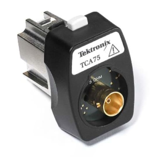
TCA75 Impedance Conversion Adapter The TCA75 (Figure 1) is a 75-to 50 Ω impedance conversion adapter with a very low VSWR (voltage standing-wave ratio). The adapter allows you to connect video and communication signals from a 75 Ω source to the 50 Ω input of oscilloscopes equipped with the TekConnect interface, while minimizing aberrations and reflections. - Page 10 The output of the TCA75 adapter connects directly to the TekConnect interface on Tektronix TDS6000, TDS7000, and CSA7000 Series oscilloscopes, as shown in Figure 2. The TCA75 is not compatible with oscilloscopes that do not have the TekConnect interface. The shell of the input on all oscilloscopes must connect to earth ground.
-
Page 11: Input Signal Connections
TCA75 Impedance Conversion Adapter Input Signal Connections The 75 Ω female BNC input of the TCA75 adapter accepts a 75 Ω male BNC connector. The signal input cable (source) must be 75 Ω. See Table 2 for typical 75 Ω signal sources. -
Page 12: Specifications
TCA75 Impedance Conversion Adapter Specifications This section contains the specifications and compliances for the TCA75 Impedance Adapter. All specifications are guaranteed unless noted as typical. Typical specifications are provided for your convenience but are not guaranteed. Specifications that are marked with the n symbol are checked in the Perfor- mance Verification on page 7. - Page 13 - - 35 - - 40 Return loss - - 45 - - 50 - - 55 - - 60 10 MHz 100 MHz 1 GHz 10 GHz Frequency Figure 3: Typical VSWR and return loss TCA75 Impedance Conversion Adapter Instructions...
- Page 14 TCA75 Impedance Conversion Adapter TCA75 Impedance Conversion Adapter Instructions...
-
Page 15: Performance Verification
Use the following procedures to verify the warranted specifications of the TCA75 adapter. Before beginning these procedures, photocopy the test record on page 12, and use it to record the performance test results for your TCA75 adapter. The recommended calibration interval is one year. -
Page 16: Output Impedance
1. Set up the multimeter as follows: Multimeter Setting Ω 4 Wire Mode 100 Ω Range 2. Connect the TCA75 adapter as shown in Figure 4. BNC to banana adapters Multimeter 50.00 Ω 50 Ω BNC 50 Ω BNC TCA75 Adapter... -
Page 17: Input Impedance
Performance Verification Input Impedance This test checks the 75 Ω input impedance of the adapter. 1. Connect the TCA75 adapter as shown in Figure 5. BNC to banana adapters Multimeter 75.00 Ω 75 Ω BNC 75 Ω BNC TCA75 Adapter... -
Page 18: Attenuation Accuracy
Figure 6: Measuring the attenuation accuracy 3. Power on the power supply, and adjust the output until multimeter #1 reads 1.000 V. 4. Check that the voltage is attenuated by 2.46X ±1.5% (multimeter #2 reads 0.402 V to 0.414 V). TCA75 Impedance Conversion Adapter Instructions... - Page 19 8. Power off the power supply, and disconnect the test setup. Probe Calibration Routine This is a functional check of the TCA75 adapter that uses the probe calibration output signal and probe calibration feature of the oscilloscope. 1. Connect the TCA75 adapter to any channel on the oscilloscope.
- Page 20 (measured with 1.0 V on the input) Input voltage 1.000 1.000 ÷__________ ÷__________ Output voltage 0.402 .414 Input ÷ output = attenuation factor 2.415 = __________ = __________ 2.487 Probe Calibration Routine Pass/Fail __________ __________ TCA75 Impedance Conversion Adapter Instructions...
Need help?
Do you have a question about the TCA75 and is the answer not in the manual?
Questions and answers