Table of Contents
Advertisement
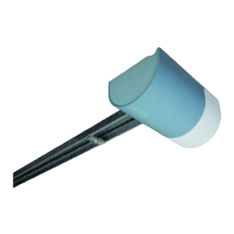
Shel50Kit
Shel75Kit
Garage door opener
EN -
Instructions and warnings for installation and use
IT -
Istruzioni ed avvertenze per l'installazione e l'uso
FR -
Instructions et avertissements pour l'installation et l'utilisation
ES -
Instrucciones y advertencias para la instalación y el uso
DE -
Installierungs-und Gebrauchsanleitungen und Hinweise
PL -
Instrukcje i ostrzeżenia do instalacji i użytkowania
NL -
Aanwijzingen en aanbevelingen voor installatie en gebruik
Advertisement
Table of Contents

Subscribe to Our Youtube Channel
Related Manuals for Nice Shel50Kit


Summary of Contents for Nice Shel50Kit
- Page 1 Shel50Kit Shel75Kit Garage door opener EN - Instructions and warnings for installation and use IT - Istruzioni ed avvertenze per l’installazione e l’uso FR - Instructions et avertissements pour l’installation et l’utilisation ES - Instrucciones y advertencias para la instalación y el uso...
-
Page 3: Table Of Contents
Contents ENGLISH GENERAL SAFETY WARNINGS AND PRECAUTIONS STEP 1 – Working in safety! ......... . . 2 –... -
Page 4: General Safety Warnings And Precautions
III. If in any doubt regarding installation, do not proceed and contact the Moovo – if the power cable is damaged, it must be replaced by Nice, by the assigned Technical Assistance Nice for clarifications. technical service centre or in any event by a person with similar qualifications to If this is the first time you are setting up an automation for garage doors (section- prevent all risks. -
Page 5: Step 3
The socket must be limits of use: positioned so that after connection of the power cable plug, the cable does not hang in the vicinity of mobile parts or hazardous areas. SHEL50KIT SHEL75KIT Sectional doors 350 x 240 cm... -
Page 6: Step
Technical specifications of electric cables (note 1) Devices Terminals Function Cable type Maximum admissible length Safety 3 - 5 PHOTO input TX Cable 2 x 0,25 mm 20 m (note 2) photocells RX Cable 3 x 0,25 mm 20 m (note 2) Control 3 - 4 Input... -
Page 7: Step 7
Then align the drive rod along the trajectory of the guide and fix the brack- WARNING – On completion of connections, secure all cables using special et to the door using rivets or screws suited to the door material (fig. 29). clamps and refit the cover on the control unit. -
Page 8: Step 9
insufficient. In this case, interrupt the procedure by pressing “P1” on the control unit: then tension the chain by tightening nut and repeat the pro- PROGRAMMING THE AUTOMATION cedure from the beginning. This procedure can be repeated at any time: for example after a mechanical STEP 9 travel stop has been moved on the guide. -
Page 9: Memorisation Of A New Transmitter With Control Unit "In The Vicinity
Notes to Table 4: Deleting other data memorised on the control unit – The Table states the values available for each of the 4 special functions and The following procedure enables deletion of various types of memorised data the corresponding key to be pressed on the transmitter for selection of the spe- from the control unit memory, as specified in Table 5. -
Page 10: What To Do If
Overall layout drawing (see example in fig. 6, 7, 8), AUTOMATION TESTING electrical wiring diagram (see example in STEP 6), risk assessment and rela- 1 Ensure that all specifications in STEP 1 regarding safety have been strictly tive solutions adopted (see forms to be compiled on the website www.nice-... -
Page 11: Product Disposal
CE DECLARATION OF CONFORMITY Note: The contents of this declaration correspond to those of the last revision available of the official document, deposited at the registered offices of Nice S.p.a., before printing of this manual. The text herein has been re-edited for editorial purposes. -
Page 12: Technical Specifications Of Components
– All technical specifications stated in this section refer to an ambient temperature of 20°C (± 5°C). – Nice S.p.a. reserves the right to apply modifications to the product at any time when deemed necessary, while maintaining the same functionalities and intended use. - Page 13 In order to do this you need to manually release the gearmotor (this operation is the only one that the user of the automation is authorized to per- form): This operation has been carefully designed by Nice to make it extremely easy, without any need for tools or physical exertion.
- Page 14 • SECTIONAL • SEZIONALE • PROJECTING • DEBORDANTE • NON-PROJECTING • NON DE- • SECTIONNELLE • SECCIONAL • DÉBORDANTE • DESBORDANTE BORDANTE• NON DÉBORDANTE • SEKTIONALTOR • AUSFAHREND • WYSTAJĄCA • NO DESBORDANTE • NICHT AU- • BRAMA SEGMENTOWA • BUITEN DE GEVEL DRAAIEND SFAHREND •...
- Page 16 V6 x 30 (• open • aperta • ouverte • abierta • geöffnet • otwarta • open) V3,5 x 15 V8 x 45...
- Page 17 17-a 17-b V8 x 45 R8 x 24 V6 x 18...
- Page 18 (4 ÷ 400 mm) 25-a V6 x 14 90°...
- Page 19 + – + – 1 2 3 4 5 1 2 3 4 5 + – + – + – + – 1 2 3 4 5 2 3 4 5...
- Page 20 1 2 3 4 5 1 2 3 4 5 1 2 3 4 5 1 2 3 4 5 “NA” “NC” 1 2 3 4 5 • P1 • Green Led - Led verde - Led verte - Led verde - grüne Led - Zielona dioda - Groene led •...
Need help?
Do you have a question about the Shel50Kit and is the answer not in the manual?
Questions and answers