
Related Manuals for Nice SO2000


Summary of Contents for Nice SO2000
- Page 1 Nice SO2000 Garage door opener EN - Instructions and warnings for installation and use...
-
Page 2: Table Of Contents
GENERAL SAFETY WARNINGS AND ENGLISH PRECAUTIONS Translation of the original instructions in full GENERAL SAFETY WARNINGS AND PRECAUTIONS 1.1 IMPORTANT INSTALLATION INSTRUCTIONS WARNING – To reduce the risk of severe CONTENTS injury or death: • READ AND FOLLOW ALL INSTALLATION IN- GENERAL SAFETY WARNINGS AND PRECAUTIONS . -
Page 3: Important Safety Instructions
• After installing the opener, the door must reverse • The product must not be installed outdoors. when it contacts a 38-mm (1-1/2-inch) high object • Prior to installing the drive motor, check that the door (or a 2 by 4 board laid flat) on the floor. is in good working order, correctly balanced and that it •... -
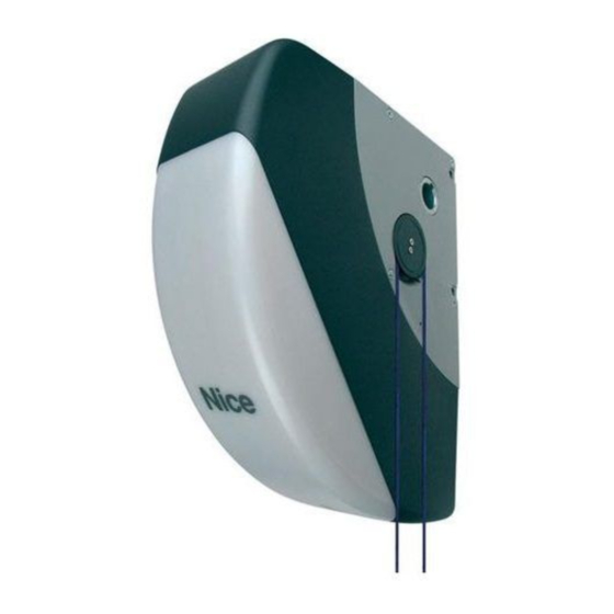
Page 4: Product Description And Intended Use
Use caution when using this release with the door PRODUCT DESCRIPTION AND INTENDED USE SO2000 is an electromechanical actuator for automating sectional open. Weak or broken springs are capable of in- doors up to 215ft2 40in2 1/16 (20mq). Thanks to the cable outlet... -
Page 5: Installation
– the door dimensions must be below 215ft2 40in2 1/16 (20mq) door”) and 10% (“Ambient temperature above 40°C or below 0°C – the drive shaft must be compatible with the SO2000 output and or humidity above 80%”). the relative keys supplied with the package These indicators must be added together to obtain the overall se- –... -
Page 6: Product Identification And Overall Dimensions
3.3 PRODUCT IDENTIFICATION AND OVERALL Table 3 DIMENSIONS PRODUCT DURABILITY The overall dimensions and label (A) that allow for identifying the Severity index product are shown in “Figure 3”. < 200lb 7oz < 100 kg Weight of the 200lb 7oz - 396lb 13oz 100 - 180 kg door 396lb 13oz - 507lb 1oz... -
Page 7: Pre-Installation Works
3.5 PRE-INSTALLATION WORKS The figure shows an example of an automation system, constructed using Nice components. A Gearmotor Note 1 If the power supply cable is longer than 98ft 5in 7/64 (30 B Photocells m), a cable with larger cross-sectional area (3 x 13 AWG... -
Page 8: Installing The Gearmotor
(A) into the transmission shaft (B) of the door, coupling them with the aid of the key (C) provided SO2000 can be installed in the horizontal position using the release mechanism (F), supplied with the kit, which must be fastened with the three screws in the position shown, while making sure that the unlocking cables (G) are fed through. -
Page 9: Manually Unlocking And Locking The Gearmotor
3.7 MANUALLY UNLOCKING AND LOCKING THE insert all the connecting cables into the various devices, GEARMOTOR leaving them 8÷12 in (20÷30 cm) longer than necessary. Re- fer to “Table 4” for the type of cables and to “Figure Table The gearmotor is equipped with a mechanical unlocking device 4”... -
Page 10: Wiring Diagram And Description Of Connections
4.2 WIRING DIAGRAM AND DESCRIPTION OF CONNECTIONS 4.2.1 Wiring diagram FUSE KEYS DOOR CONTROL BUZZER Light Open Stop Bluebus Flash Alarm FLASH STOP OPEN AERIAL 4.2.2 Description of connections Table 5 ELECTRICAL CONNECTIONS Terminals Description ALARM This (programmable) output is configured as default for alarm system notifications. This output is programmable (refer to the “PROGRAMMING”... -
Page 11: Addressing Of Devices Connected With The Bluebus System
ELECTRICAL CONNECTIONS Terminals Description This terminal can be used to connect compatible devices, which are all connected in parallel with only two wires carrying both the electric power and communication signals. BLUEBUS For further information on the BlueBUS, refer to the “Addressing of devices connected with the BlueBUS system”... -
Page 12: Ft210B Photosensor
5.2 DEVICE LEARNING 4.3.1 FT210B photosensor The FT210B photosensor combines in a single device a force lim- Once the power supply has been connected, the control unit must iting system (type C, in accordance with the EN12453 standard) recognise the devices connected to the “BlueBUS” and “STOP” and a presence sensor that detects obstacles on the line of sight inputs. - Page 13 The position memorisation procedures are described below. Position RINT programming, LED “L4” flashes: Two procedures are available: If the intermediate slowdown position does not have to be – FULL: enables the user to manually set multiple positions programmed, press the button twice rapidly to skip to the next programming;...
-
Page 14: Checking The Door Movement
the courtesy light will start flashing once every second (1 To do this: Hz) to signal the need to run the MANDATORY “Automatic press the button to command an “Open” manoeuvre; Force Search” procedure. During the “Automatic Force check that the door opens properly without any speed varia- Search”... -
Page 15: Testing
Commissioning can only be performed after all for all the automation’s devices. testing phases have been successfully completed. For all the above-mentioned documentation, Nice – through its technical assistance service – provides Before commissioning the automation, ensure that the following: pre-completed forms. -
Page 16: Programming
PROGRAMMING PROGRAMMING There are 3 buttons on the control unit: (“Figure 23”) which can be used both to command the control unit during the testing phase and to programme the available functions. FUSE L1 ... L8 The available programmable functions are grouped into two levels and their operating status is signalled by eight LEDs “L1 ... -
Page 17: Level 1 Programming (On-Off)
7.2 LEVEL 1 PROGRAMMING (ON-OFF) All the Level 1 functions are factory-set to “OFF” and can be modified at any time. To check the various functions, refer to “Table 8”. 7.2.1 Level 1 programming procedure The user has maximum 10 seconds to press the buttons consecutively during the programming procedure, af- ter which time the procedure terminates automatically and memorises the changes made up to then. -
Page 18: Level 2 Programming (Adjustable Parameters)
7.3 LEVEL 2 PROGRAMMING (ADJUSTABLE PARAMETERS) All the Level 2 parameters are factory-set as highlighted in “GREY” in “Table 9” and can be modified at any time. The parameters can be set to a scale of 1 to 8. The check the value corresponding to each LED, refer to “Table 9”. 7.3.1 Level 2 programming procedure The user has maximum 10 seconds to press the buttons consecutively during the programming procedure, af- ter which time the procedure terminates automatically and memorises the changes made up to then. - Page 19 LEVEL 2 FUNCTIONS (ADJUSTABLE PARAMETERS) Entry LED Parameter LED (level) Set value Description Door Open Indicator Enabled if door closed Enabled if door open Warning light Selects the device connected to the L4** FLASH output FLASH output. Electric latch Electric lock Suction cup Maintenance indicator Force 1 (low)
-
Page 20: Programming The Direction
7.4 PROGRAMMING THE DIRECTION 7.6 SPECIAL FUNCTIONS This procedure allows for reversing the motor’s rotation direction. To do this: 7.6.1 “Always open” function press and hold the button for roughly 3 seconds The “Always open” function is a control unit feature that enables the button when LED “L1”... -
Page 21: Verifying The Number Of Manoeuvres Completed
Table 10 MAINTENANCE NOTICE THROUGH FLASH AND MAINTENANCE INDICATOR Number of Maintenance Signal on “Flash” manoeuvres indicator signal FUSE Lit for 2 seconds Below 80% of the Normal (0.5 sec on, at the start of the limit 0.5 sec off) opening manoeuvre Remains lit for 2 Flashes for the... -
Page 22: Troubleshooting Guide
TROUBLESHOOTING... (troubleshooting guide) TROUBLESHOOTING GUIDE 8.1 TROUBLESHOOTING The table below contains useful instructions to resolve any malfunctions or errors that may occur during installation or in case of a fault. Table 11 TROUBLESHOOTING Problems Recommended checks The radio transmitter does not control the automation and the LED on the transmitter Check whether the transmitter batteries are exhausted and replace them if necessary. -
Page 23: Anomaly Log
8.2 ANOMALY LOG press the button to shift the flashing LED to “L8”, that is, the “entry LED” for the “List of anomalies” param- The gearmotor allows for displaying any anomalies that occurred in eter the last 8 manoeuvres, for example, the interruption of a manoeu- press and hold the button. -
Page 24: Signals On The Control Unit
8.4 SIGNALS ON THE CONTROL UNIT FUSE The control unit has a series of LEDs, each of which can emit spe- cial signals both during regular operation and when an anomaly occurs. A BlueBus LED B Light Led, Open, Sbs, Stop C “L1 ... - Page 25 Table 16 LEDS ON THE CONTROL UNIT BUTTONS LED 1 Description During normal operation, this indicates that “Automatic Closing” is disabled. During normal operation, this indicates that “Automatic Closing” is active. Function programming in progress. With the motor stationary, if it flashes individually it means that the encoder position is in the Low Overrun position Flashes (position below or equal to 5%).
-
Page 26: Further Details (Accessories)
If required, the alarm siren can be disconnected and the ALARM FURTHER INFORMATION output can be reconfigured for other applications: in this case the (Accessories) alarm will be disabled, but all the other safety systems required to detect obstacles will remain active. FURTHER DETAILS (Accessories) The alarm system can be activated/deactivated using the Oview 9.1 MODIFYING THE STOP INPUT... -
Page 27: Connecting And Installing The Back-Up Battery
9.4 CONNECTING AND INSTALLING THE BACK- Table 17 UP BATTERY SMXI / SMXIS Receiver output Command The electrical connection of the battery to the con- Output No. 1 “Step-by-Step” trol unit must be made only after completing all the Output No. 2 “Partial opening”... -
Page 28: Connecting The Oview Programmer
9.5 CONNECTING THE OVIEW PROGRAMMER insert the back-up battery (B) into its housing inside the mo- tor body. The control unit has a BusT4 connector to which the “Oview” programmer can be connected, through the IBT4N interface. The programmer allows for fully and rapidly managing the installation, maintenance and diagnosis of the entire automation. -
Page 29: Connecting The Solemyo Solar Energy System
9.6 CONNECTING THE SOLEMYO SOLAR ENERGY SYSTEM When the automation is powered by the “Solemyo” system, IT MUST NOT BE POWERED by the electricity grid at the same time. For information on the “Solemyo” system, consult the relevant instruction manual. To connect the “Solemyo”... -
Page 30: Product Maintenance
PRODUCT MAINTENANCE PRODUCT DISPOSAL PRODUCT MAINTENANCE PRODUCT DISPOSAL The automation must be subjected to regular maintenance to keep This product is an integral part of the operator and its safety level constant and guarantee long-lasting operation; to must therefore be disposed of with it. this aim, Soon has a manoeuvre counter and maintenance warn- ing system;... -
Page 31: Technical Specifications
TECHNICAL SPECIFICATIONS TECHNICAL SPECIFICATIONS All technical specifications stated in this section refer to an ambient temperature of 20°C (± 5°C). Nice S.p.A. reserves the right to apply modifications to the product at any time when deemed necessary, without altering its functions and intended use. - Page 32 NOTES 32 – ENGLISH...
-
Page 33: Instructions And Warnings For The User
INSTRUCTIONS AND WARNINGS FOR THE USER Before using the automation for the first time, ask the installer to Safety devices out of order: the automation can also be used explain the origin of any residual risks and take a few minutes to when one or more safety devices are defective or out of order. - Page 34 Unlocking and manual movement The gate can only be unlocked once the leaf has come to a standstill. The gearmotor is equipped with a mechanical unlocking device that can be used to open and close the door manually. These manual operations should only be performed in case of a power outage, malfunctions or during the installation phases.
- Page 35 NOTES ENGLISH – 35...
- Page 36 Nice SpA Via Callalta, 1 31046 Oderzo TV Italy www.niceforyou.com info@niceforyou.com...
Need help?
Do you have a question about the SO2000 and is the answer not in the manual?
Questions and answers