RIB IDRO C 27/1B Manual
Hide thumbs
Also See for IDRO C 27/1B:
- Manual (61 pages) ,
- Simplified instructions (30 pages) ,
- Instruction for the installation (77 pages)
Table of Contents
Advertisement
Available languages
Available languages
Quick Links
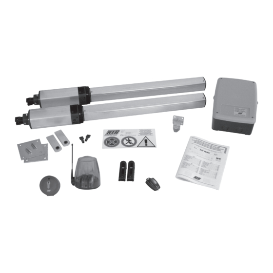
KIT IDRO C 27/1B
KIT IDRO
NUOVA VERSIONE con funzionamento a uomo presente se le fotocellule o le coste sono guaste.
NOUVELLE VERSION avec travail avec homme present, dans le cas de panne de sécurité.
NEW VERSION with functioning in dead man mode when the safety devices are failing.
NEUE VERSION mit arbeit im mannsbeisein im fall eines ausfalls der Sicherheiten.
NUEVA VERSIÓN con funcionamiento a hombre presente en caso de averías con los accesorios de seguridad.
Operatore
Operateur
Operator
Torantrieb
KIT IDRO C 27/1B
KIT IDRO C 27/1B
Wi-Fi
Conforme alle normative in vigore.
Conforme aux Normes en vigueur.
According to current European Norms.
In Übereinstimmung mit der aktuellen Normen.
En conformidad a las Normas en vigor.
Alimentazione
Peso max anta
Alimentation
Poids maxi battant
Power Supply
Max leaf weight
Stromspannung
Max. Torgewicht
230V ~ 50/60Hz
230V ~ 50/60Hz
ITALIANO pag. 04 / ENGLISH pag. 17
Lunghezza max. anta
Longueur maxi du battant
Max. leaf length
Max. Torflügelweite
250 kg
250 kg
KIT IDRO Wi-Fi
codice
AD00752
2 m
AD00754
2 m
code
code
code
Advertisement
Table of Contents

Related Manuals for RIB IDRO C 27/1B


Summary of Contents for RIB IDRO C 27/1B
- Page 1 KIT IDRO C 27/1B KIT IDRO KIT IDRO Wi-Fi NUOVA VERSIONE con funzionamento a uomo presente se le fotocellule o le coste sono guaste. Conforme alle normative in vigore. NOUVELLE VERSION avec travail avec homme present, dans le cas de panne de sécurité.
-
Page 2: Importanti Istruzioni Per La Sicurezza
(ex. en l’installant dans un coffre fermant 2° - Per la sezione ed il tipo dei cavi la RIB consiglia di utilizzare un cavo di tipo H05RN-F à clé). -
Page 3: Installation
Konformitätszeichen besitzt. Solch ein Geraet muss vor Vandalismus 2° - As far as the cable section and the cable kind are concerned, RIB suggests to use an geschuetzt werden(z.B.mit einen Schluesselkatsten in einem Panzergehaeuse) H05RN-F cable, with a minimum section of 1,5mm 2 , and to follow, In any case, the 2°... - Page 4 EN12453 - Appendice A E: Fotocellule, es. cod. ACG8026 (Da applicare ogni 60÷70 cm per tutta l’altezza della colonna del cancello fino ad un massimo di 2,5 m - EN 12445 punto 7.3.2.1) IDRO C 27/1B CARATTERISTICHE Tensione di alimentazione monofase 230 V±10% 50/60Hz Hz...
-
Page 5: Posizionamento Attacchi
ALLACCIAMENTO ELETTRICO DEL SISTEMA - Per eseguire gli allacciamenti elettrici attenersi scrupolosamente alle Attenzione istruzioni allegate ai singoli componenti seguendo lo schema riportato in • Ogni attuatore è fornito con condensatore di spunto compreso nell’imballo. Al momento dell’installazione, collegare il condensatore all’interno dell’apparecchiatura elettrica in base allo schema di Attenzione collegamento della stessa. -
Page 6: Fissaggio Piastre Di Ancoraggio
Attenzione • Qualora le dimensioni della colonna lo consentano, utilizzare la piastra standard RIB in dotazione. 3.1.2 Attuatore fissato su colonne in legno Se le colonne di sostegno delle ante del cancello sono in legno, occorre applicare una piastra di rinforzo da spigolo a spigolo della colonna, per la saldatura dell’attacco posteriore dell’attuatore. - Page 7 Cautela • Le dimensioni delle piastre, escluso quelle standard RIB, vanno proporzionate alle dimensioni delle colonne. • Se si utilizza la piastra di tipo A e si rendesse necessario posizionarla in asse con l’attuatore, occorre modificare le zanche nel modo indicato in fig. C7.
- Page 8 FISSAGGIO ATTACCO POSTERIORE DELL’ATTUATORE Posizionare l’attacco posteriore in base alle quote stabilite precedentemente e fissarlo alla piastra di ancoraggio con due punti di saldatura (C11). Controllare con una livella l’allineamento longitudinale e trasversale (C12) dell’attacco. Completare la saldatura e rimuovere le scorie con una spazzola metallica.
- Page 9 POSIZIONAMENTO ATTACCO ANTERIORE C16b Spalmare di grasso il gambo filettato dello snodo sferico (C16 pos.1), inserire nell’asta dell’attuattore lo snodo sferico corredato di dado (C16 pos.2) e, avvitandolo per circa metà filetto, inserire nello snodo sferico il perno (C16 pos.4) dell’attacco anteriore senza bloccarlo con il relativo seeger.
-
Page 10: Collegamento Elettrico
3.5.2 Controlli sulla movimentazione Attenzione • A montaggio effettuato movimentare manualmente le ante, dopo avere neutralizzato (se presente negli attuatori) il blocco idraulico tramite l’apposita chiave ruotando la stessa di 180° in senso antiorario, per controllare la loro scorrevolezza; eseguire l’operazione molto lentamente per evitare che gli attuatori aspirino aria e di conseguenza si renda necessario lo spurgo degli stessi. -
Page 11: Controlli E Regolazioni
Inserire se necessario, nel cavo di alimentazione (E5 pos. 5) una guaina di protezione. Cautela É normale la fuoriuscita di una goccia di olio idraulico dal condotto aperto dalla eliminazione della vite (E5 pos. 4). Informazioni Al termine dell’installazione è necessario corredare il cancello con l’apposito cartello di segnalazione. -
Page 12: Manutenzione
Insufficiente quantità di olio all'interno del Verificare la presenza di eventuali perdite di olio e, funziona a scatti cilindro. se presenti, contattare il Centro riparazioni RIB. Gli attacchi anteriori e posteriori dell'attuatore Ripristinare o rinforzare gli attacchi. flettono o sono fissati in modo inadeguato. -
Page 13: Collegamenti Elettrici
cod. BC07086 COLLEGAMENTI ELETTRICI T2 CRX cod. BC07085 LAMPEGGIATORE CONDENSATORE MOTOR 2 ANTENNA CONDENSATORE MOTOR 1 CALZA ANTENNA R=2,2KΩ SPIA BUZZER 12 Vdc per AUTOTEST PER COSTA 12 Vdc per ACCESSORI FOTOCELLULE ALIMENTAZIONE COSTE 230Vac 50 Hz PASSO PASSO PEDONALE COMUNE SERRATURA ELETTRICA... - Page 14 Morsettiera per il collegamento alla sonda riscaldatore incorporata solo per motoriduttore King Ice (cod. AA14019) Modulo radio incorporato (modello CRX), o connettore per radio ricevitore RIB ad innesto con alimentazione a 12 Vdc Selezione funzionamento con 1 o 2 motori...
- Page 15 cancello si dovrà aprire con sfasamento fisso delle ante di due secondi (il movimento è eseguito ad secondi. uomo presente, apre-chiude-apre-etc...). Verificare il movimento delle ante e regolare la posizione 3 - Premere e mantenere premuto il pulsante PROG per 5 secondi. La cancellazione della memoria dei finecorsa meccanici di apertura.
- Page 16 Durante l’apertura, la pausa o la chiusura pedonale, è possibile comandare l’apertura da qualsiasi La segnalazione dell’attivazione di questo funzionamento è data dal led di programmazione che comando collegato sulla scheda. lampeggia. Tramite DIP 6 è possibile scegliere la modalità di funzionamento del pulsante di comando pedonale. Con questo funzionamento viene consentita l’apertura o la chiusura solo mantenendo premuti i pulsanti Se DIP6 su OFF =>...
-
Page 17: Technical Data / Installation
E: Photocells, like code ACG8026 (To apply every 60÷70cm for all the height of the column of the gate up to a maximum of 2,5m - EN 12445 point 7.3.2.1) CARACTERISTIQUES IDRO C 27/1B Single-phase system voltage 230 V±10% 50/60Hz Hz... -
Page 18: System Layout
SYSTEM ELECTRICAL CONNECTION - When making the electrical connections,carefully follow the Warning instructions for each of the components, referring to the wiring • Every operator comes complete with a pickup capacitor. During diagram B1. installation, connect the capacitor to the electrical equipment according to the wiring diagram supplied. - Page 19 Position the reinforcing plate (C3 pos. 2) in the rear mounting welding zone and weld it on the column, covering it from edge to edge. The size of the reinforcing plate must be in proportion to the size of the column. Warning • If the size of the column allows for it, use the RIB standard plate provided. 3.1.2 Operator fixed on wooden posts...
-
Page 20: Rear Operator Mounting - Special Cases
Caution • The size of the plates, apart from standard RIB plates, must be proportioned to the size of the columns. • If the A-type plate is used and has to be positioned in line with the operator axis, the hook fittings must be modified as shown in fig. - Page 21 FIXING THE REAR OPERATOR MOUNTING Position the rear mounting at the height previously measured and weld it on the anchorage plate with two weld points (C11). Check the lengthwise and crosswise alignment of the mounting (C12) with a water level. Complete the welding and clean away the residues with a wire brush.
-
Page 22: Mechanical Fixing
POSITIONING THE FRONT MOUNTING C16b Spread grease on the threaded stem of the ball joint (C16 pos. 1), fit the ball joint, along with its nut (C16 pos. 2) and to the operator arm, screwing on to about halfway along the thread. Insert the pin (C16 pos. -
Page 23: Electrical Connection
3.5.2 Checking the motion Warning • When the mounting is completed, neutralize the hydraulic lock (if present in the operators) by turning the correct key through 180° counter-clockwise, and move the gate-leaves manually to check on the smoothness of the movement; this should be done very slowly, otherwise the operators will take in air and, consequently, will have to be bled. -
Page 24: Checks And Adjustments
Fit the protective sheath to the power supply cable (E5 pos. 5) if necessary. Caution One drop of hydraulic oil coming out of the duct created by the screw elimination (E5 pos. 4) is normal. Information After installation, an appropriate warning sign must be attached to the gate 3.5.5 Bleeding Warning... -
Page 25: Notes For The Installer
During the motion, the operator jerks. Check for oil leaks; if any, address to an Oil in the cylinder not enough. RIB Repair Centre. The front and rear operator mountings Repair or strengthen the mountings. move or have been fitted incorrectly. - Page 26 code BC07086 ELECTRIC CONNECTIONS T2 CRX code BC07085 BLINKER CAPACITOR M2 MOTOR 2 AERIAL CAPACITOR M1 MOTOR 1 COAX R=2,2KΩ SIGNAL BUZZER 12 Vdc for AUTOTEST EDGE 12 Vdc for ACCESSORY PHOTOCELL SUPPLY POWER SUPPLY EDGE K BUTTON PED. BUTTON ELECTRIC LOCK JP17...
- Page 27 OTHERWISE THE OPERATOR WILL NOT WORK! PROBE Terminal block to connect the heater sensor only for operator (code AA14019) Built-in radio module (model CRX), or connector for radio receiver RIB, 12 Vdc supply To select 1 motor (M1) or 2 motors (M1 and M2) JP17...
- Page 28 6 - Reposition DIP 1 to OFF and DIP 2 to OFF. POINT C - MOTOR ROTATION DIRECTION CHECK 7 - You have completed the procedure 1 - Unlock the operators with the Manual Release - swing open the leaves about halfway and lock again the PROCEDURE FOR DELETING ALL RADIO CODES USED ONLY FOR COMPLETE OPENING operators.
- Page 29 AUTOMATIC CLOSING (from the COMPLETE open position) button pressed and held. The radio commands and that of automatic closing, will be excluded, since their use in this The Automatic Closing from the complete open position can be enabled turning ON the DIP3. mode, is not allowed by the norms.
- Page 30 REGISTRO DI MANUTENZIONE - DOSSIER D’ENTRETIEN MAINTENANCE LOG - WARTUNGSREGISTER Il presente registro di manutenzione contiene i riferimenti tecnici e le registrazioni delle attività di installazione, Ce dossier d’entretien contient les références techniques et les enregistrements des opérations d’installation, d’entretien, manutenzione, riparazione e modifica svolte, e dovrà...
- Page 31 R.I.B. S.r.l. AZIENDA CON SISTEMA DI QUALITÀ CERTIFICATO 25014 Castenedolo - Brescia - Italy DA DNV Via Matteotti, 162 Tel. ++39.030.2135811 COMPANY WITH QUALITY Fax ++39.030.21358279 - 21358278 SYSTEM CERTIFIED BY DNV www.ribind.it - ribind@ribind.it DICHIARAZIONE DI CONFORMITÁ - DECLARATION OF COMPLIANCE DÉCLARATION DE CONFORMITÉ...
- Page 32 KIT IDRO C 27/1B RICAMBI ATTUATORE IDRO CODICE DESCRIZIONE Qtà min ord. CONF.ATTACCO POSTERIORE CONDENSATORE 8µF TIRANTE FLANGIA ANTERIORE FLANGIA POSTERIORE POMPA MOTORE TAPPO SERBATOIO TIRANTE POSTERIORE DISTRIBUTORE CONF.ATTACCO ANTERIORE 8 (min 4pz) FLANGIA ANTERIORE GUARN.TENUTA CANNA GUARN.SERBATOIO PISTONE CANNA...
Need help?
Do you have a question about the IDRO C 27/1B and is the answer not in the manual?
Questions and answers