Table of Contents
Advertisement
Advertisement
Table of Contents

Related Manuals for Hollis LTS Series


Summary of Contents for Hollis LTS Series
- Page 1 BC MANUAL...
- Page 2 This Hollis BC Owners Manual is copyrighted and all rights are reserved. It may not, in whole or in part, be copied, photocopied, reproduced, translated, or reduced to any electronic medium or machine-readable form without prior consent in writing from Hollis.
- Page 3 CE CERTIFICATION All Buoyancy Control Devices sold by Hollis in the EU (European Union) meet the following Personal Protective Equipment requirements, and compliance with the following where applicable: Regulation (EU) 2016/425 of the European Parliament and of the Council of 9 March 2016 on personal protective equipment and repealing Council Directive 89/686/EEC.
- Page 4 WARRANTY REGISTRATION Please take a moment to locate, complete and return your warranty registration card to Hollis. This card is very important. It will help you obtain warranty service and it provides us a means to contact you in the event of safety notices, service updates, or changes regarding this product.
- Page 5 • DO NOT inhale gases from within any Hollis BCD. Doing so can lead to serious injury or death. • If you do not fully understand how to use your Hollis BCD product, or if you have any questions regarding its functions, you should seek instruction in its use from your authorized Hollis dealer before you utilize this product.
-
Page 6: Table Of Contents
Integrated Weight System (Style 1) ..............19 Integrated Weight System (Style 2) ..............21 Donning and Fitting ....................23 Hollis Sidemount Diving Systems ................24 Hollis BCD Wings ....................... 31 Inflator and Dump Valve Use ................32 Hollis Backplates Assembly ..................34... -
Page 7: Introduction
INTRODUCTION ASSESSMENT OF RISK Hollis BCD’s are designed and intended for use by divers who have successfully completed a nationally recognized course in scuba diving. Hollis equipment must NOT be used by untrained persons who may not have knowledge of the potential risks and hazards of scuba diving. As with all underwater life support equipment, improper use or misuse of this product can cause serious injury or death. -
Page 8: Care And Maintenance
CARE AND MAINTENANCE Your Hollis BCD is a reliable piece of equipment that was designed to withstand the rigors of diving. It will last for many years if cared for properly. Follow the procedures on the next page to ensure a long life for your BCD. - Page 9 Before each dive check to make sure your equipment is working properly. If any piece of equipment is not working properly, DO NOT USE! If damaged, return to your authorized Hollis dealer for repair. • Under pressure, attach the low pressure inflator hose to the inflator and depress the inflator button to make sure it is working properly.
-
Page 10: Adjustments
ADJUSTMENTS Most Hollis BCD’s do not require any assembly, but there are adjustments and items that can be removed or added to your Hollis BCD to customize it for best fit. CUMMERBUND ASSEMBLY If your Hollis BCD product comes equipped with an adjustable cummerbund, you can access the cummerbund for adjustment by removing the top of the back pad that is attached to the harness with an elastic loop (Fig. - Page 11 Fig. 5 STERNUM STRAP For Hollis BCD’s equipped with sternum straps, the position of the strap is adjustable. It can be installed in one of multiple positions or simply removed to suit diver preference (Fig. 6, 7, 8). Fig. 7 Fig.
- Page 12 WAIST BUCKLE Insert the waist buckle on the left side of the waist webbing. See pictures for recommended buckle weave (Fig. 9). When at the desired length, pull the remaining webbing through the first slot and tighten (Fig. 10). Fig. 9 Fig.
- Page 13 CROTCH STRAP For Hollis BCD's equipped with crotch straps: Take the side of the crotch strap that is not looped in hand. Insert the belt slide, leaving about 8 in (20.3 cm) of webbing between the belt slide and the end of the webbing (Fig.
-
Page 14: Attaching A Tank
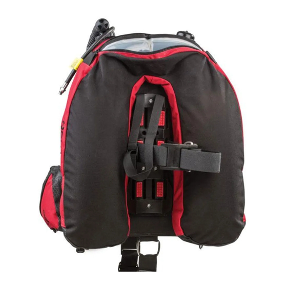
ATTACHING A TANK Most Jacket-style Hollis BCD’s are only designed to handle a single tank and use a single cam band against a contoured hard plastic backplate that holds the tank securely (Fig. 14). Hollis products designed for double tanks, or having that option will be marked on the BCD’s product tag. Use the attached adjustable guide strap to position the tank on the contoured backplate by placing it around the neck of the tank (Fig. - Page 15 CAUTION: Use the following steps to weave the cam band. Nylon may loosen when wet. To ensure a secure hold, soak the straps in water before tightening. Use the following steps to weave the cam bad: • Pull the band through SS (Stainless Steel) attachment at the base of the buckle (Labeled 1) so the band is now on the outside of the buckle (Fig.
- Page 16 • With the band tight, weave the band through the top slot (Labeled 4) of the buckle from inside to outside (Fig. 21). Pull tight and fold the buckle over so it snaps against the tank (Fig. 22, 23). Now attach remaining webbing to the webbing against the tank using the self gripping patch (Fig.
-
Page 17: Inflator And Dump Valve Use
INFLATOR AND DUMP VALVE USE LP Hose Connector Power Inflator Button Mouthpiece Deflate / (Manual Inflate) Button Working Pressures: min = 120 psi (8 Bar), nominal = 140 psi (9 Bar), max = 160 psi (11 Bar) NOTE Install the inflator hose to your regulator per your regulator’s instructions, or have an authorized technician attach the LP hose to the regulator first stage. MANUAL INFLATION To manually inflate the BCD, depress the manual inflation button and blow into the mouthpiece. Be sure to release the manual inflation button before you remove your mouth from the mouthpiece to ensure you do not lose any air through the mouthpiece. - Page 18 WARNING I f you depress the Power Inflator fully, the BCD will inflate rapidly. Be careful not to overinflate the BCD causing an unwanted rapid rise towards the surface. DEFLATING THE BCD WITH POWER INFLATOR OR DUMP VALVE To deflate the BCD using the inflator, hold the inflator higher than the top of the BCD and depress the deflate button to release the air. To deflate using the dump valve, lightly pull outwards and upwards. The mouthpiece or dump valve must be at the highest point of the BCD to ensure complete deflation of the BCD.
-
Page 19: Integrated Weight System (Style 1)
INTEGRATED WEIGHT SYSTEM (STYLE 1) LOADING WEIGHT POUCHES INTO WEIGHT POCKETS Squeeze the tabs and pull the handle to remove the weight pouch from the pocket (Fig. 25). Open the flap of the weight pouch. Insert the desired weight into the pouch and secure the flap of the weight pouch with the self gripping fastener. - Page 20 WARNING Check the maximum weight capacity for each Weight Release Pocket and DO NOT attempt to overload the pockets with excess weight. Amounts that you can actually load may be less due to the type and shape of weights being used. DROPPING WEIGHT POUCHES FROM THE POCKET In an upright position, grasp the handles of both pouches (right and left).
-
Page 21: Integrated Weight System (Style 2)
INTEGRATED WEIGHT SYSTEM (STYLE 2) LOADING WEIGHT POUCHES INTO WEIGHT POCKETS Style 2 utilizes removable zippered weight pouches. Each pouch can be filled with hard or soft weight. Once loaded with weight, place the weight pouches inside the pockets located at the waist, as shown (Fig. - Page 22 WARNING The maximum weight capacity for each weight release pocket is 5 lbs (2.27 kg). Amounts that you can actually load may be less due to the type and shape of weights being used. WARNING Prevent the weight from getting hung up in the pockets by ALWAYS using the included zippered pouches and NEVER overloading the pockets.
-
Page 23: Donning And Fitting
Fine tune the fit as needed. NOTE If you have any questions regarding your Hollis gear, visit your authorized Hollis retailer or contact Hollis Inc. and speak with one of our technical support representatives. -
Page 24: Hollis Sidemount Diving Systems
35lb / 156N Single 15L / Dual 12L All Hollis Sidemount Harnesses are ideal for sidemount cave divers, but can be used for any level of diving. Whether you are a beginner, advanced Open Water or technical diver, this kit is designed for you. - Page 25 SMS75 HARNESS SYSTEM Shoulder webbing woven through wing slots - Longer length to support weights Grommets for bungee attachment Embroidered Hollis Logo SMS Wing -40lb/18kg Lift - 360 degree wing Alternate mounting points for rail system Rear mounted dual offset D-ring for attaching accessories...
- Page 26 Shoulder Webbing woven through wing slots - Long to support shoulder weights 1” D-rings on for bungee attachment – Top D-rings are preferred placement Embroidered Hollis logo SMS100 Wing - 52 lbs. lift - 360 Degree wing Alternate mounting points for rail system Rear mounted 2”...
- Page 27 SMS KATANA SIDEMOUNT HARNESS One size fits all design. Rear pull dump Reversable Inflator/Dump assembly Primary bungees integrated into the wing to pull tanks up and away from divers torso. 35 lbs / 15.8 kg lift. Padded spine / weight system cover H harness designed for simplicity Two 5 lbs / 2.23 kg non-ditchable weight pockets One 3 lbs / 1.36 kg non-ditchable trim weight...
- Page 28 HOW TO “RIG” YOUR CYLINDERS Right side cylinder Elastic tank bungee 7 ft. low pressure hose w/bolt snap, connected to primary 2nd stage 30 in. low pressure hose w/regulator necklace, connected to alternate 2nd stage. Left side cylinder Brass SPG w/ 6” HP hose 2nd stage (212 adjustable unit shown) Alternate low pressure quick disconnect hose –...
- Page 29 ATTACHING CYLINDERS TO THE SMS SIDEMOUNT HARNESS Sidemount Cylinder Harness Kit. (Sold separately). Kit includes the following (Fig. 31): • SS Cam Bands – Qty 2 • SS Tri-Glides – Qty 2 • SS Bolt Snaps 4.5” – Qty 4 •...
- Page 30 FINAL CONFIGURATION Your Katana Sidemount Harness comes pre-assembled which makes final configuration much easier. The last step is the adjustment of the harness is to ensure proper fit when donning the harness. First tighten the waist strap. This will help the following steps pull the harness tight against the body. Next, secure the sternum strap to its appropriate length.
-
Page 31: Hollis Bcd Wings
HOLLIS BCD WINGS C60LX, C45LX, S38LX, S25LX Lift Capacity Maximum Tank Size C60LX 60lb / 27.2kg Single 20L / Dual 15L C45LX 45lb / 20.4kg Single 15L / Dual 12L S38LX 38lb / 17.2kg Single 15L S25LX 25lb / 11.3kg... -
Page 32: Inflator And Dump Valve Use
INFLATOR AND DUMP VALVE USE LP Hose Connector Power Inflator Button Mouthpiece Deflate / (Manual Inflate) Button Working Pressures: min = 120 psi (8 Bar), nominal = 140 psi (9 Bar), max = 160 psi (11 Bar) NOTE I nstall the inflator hose to your regulator per your regulator’s instructions, or have an authorized technician attach the LP hose to the regulator first stage. MANUAL INFLATION To manually inflate the bladder, depress the manual inflation button and blow into the mouthpiece. Be sure to release the manual inflation button before you remove your mouth from the mouthpiece to ensure you do not lose any air through the mouthpiece. - Page 33 WARNING I f you depress the Power Inflator fully, the bladder will inflate rapidly. Be careful not to overinflate the BCD causing an unwanted rapid rise towards the surface. DEFLATING THE BLADDER WITH POWER INFLATOR OR DUMP VALVE To deflate the bladder using the inflator, hold the inflator higher than the top of the bladder and depress the deflate button to release the air. To deflate using the dump valve or, lightly pull the knob outwards and upwards.
-
Page 34: Hollis Backplates Assembly
HOLLIS BACKPLATES ASSEMBLY SOLO HARNESS ASSEMBLY SOLO HARNESS PARTS Note: Backplate not included... - Page 35 SHOULDER STRAPS ASSEMBLY Insert main harness webbing through top slot of plate that would be on your right shoulder. Make sure the grommet is in front of the plate with about 6 inches (15.2 cm) of webbing between the grommet and the front of the plate (Fig.
- Page 36 Fig. 33 Fig. 34 Fig. 35 Fig. 36 Fig. 37...
- Page 37 SHOULDER PADS Make sure when installing the shoulder pads that they curve away from the center of the backplate; they will then wrap naturally around your body. Each pad has 3 elastic slots that the webbing must weave through (Fig. 38). Between the elastic slots are 2 spaces for included D-rings. Slide the pad on to the harness webbing to where you feel it will sit best on your shoulder and insert D-rings with belt slides between each elastic slot to hold the shoulder pad in place (Fig.
- Page 38 WAIST STRAPS Making sure the shoulder straps contour in and around the body, pull the webbing through the lower inside slots on both sides. Insert webbing through a metal keeper on the backside of the backplate and then back through the lower outside slot. The webbing should now be on the front side of the plate, as shown (Fig.
- Page 39 CROTCH STRAP Take the side of the crotch strap that is not looped; secure a D-Ring with a belt slide. Leave about 8 inches (20.3 cm) of webbing between the slide and the end of the webbing. Then weave webbing through the backplate from the back side (Fig.
- Page 40 WAIST BUCKLE Insert the waist buckle on the left side of the waist webbing. See pictures for recommended buckle weave. Weave (Fig. 47). When at the desired length pull the remaining webbing through the first slot and tighten (Fig. 48). Fig.
-
Page 41: Elite 2 Harness Assembly
ELITE 2 HARNESS ASSEMBLY ELITE 2 HARNESS PARTS WAIST/LOWER SHOULDER UPPER SHOULDER CROTCH STRAP ASSEMBLY ASSEMBLY ASSEMBLY... - Page 42 WAIST STRAP The Elite 2 comes with two lengths of 2 inch (5.1 cm) nylon webbing straps. Use the shorter of the two to construct the waist strap assembly. Working from the backside of the backplate, run the 2 inch (5.1 cm) nylon webbing through the waist slots on the backplate as shown (Fig.
- Page 43 UPPER SHOULDER STRAP With the longer of the two lengths of webbing provided with the Elite 2, weave the strap as follows. From the back side of your backplate insert the webbing as shown (Fig. 54, 55, 56). Fig. 54 Fig.
- Page 44 Fig. 60 Fig. 61 Fig. 62 Take one of the two D-Rings with the webbing leads and clips attached and weave the webbing as shown (Fig. 64). Make sure the larger female clip faces down. The sternum strap (lead with the smaller clip) should face inward toward the center chest (Fig.
- Page 45 CROTCH STRAP Take the side of the crotch strap that is not looped; secure a D-Ring with a belt slide leaving about 8 inches (20.3 cm) of webbing between the slide and the end of the webbing. Then weave webbing through the backplate from the back side (Fig.
- Page 46 WAIST BUCKLE Insert the waist buckle on the left side of the waist webbing. See pictures for recommended buckle weave. Weave (Fig. 70). When at the desired length pull the remaining webbing through the first slot and tighten (Fig. 71). Fig.
- Page 47 ASSEMBLY OF BACKPLATE ONTO WING Fig. 72 Fig. 73 Fig. 74 Fig. 74 POST DIVE CARE Rinse with fresh water and allow to air dry.
- Page 48 HOLLIS 1540 North 2200 West 888-270-8595 Salt Lake City, www.Hollis.com Utah 84116 ©2018 Hollis. All rights reserved. Doc. No. HO.02.05.0009 (5/24/18)
Need help?
Do you have a question about the LTS Series and is the answer not in the manual?
Questions and answers