Advertisement
Quick Links
Advertisement

Summary of Contents for DEFYGRAVITY SHERCO 250-300 SE/R
- Page 1 INDEX n FRANÇAIS P. 1 n ENGLISH P. 68 n ESPAGNOL P. 135...
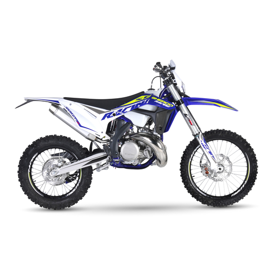
- Page 2 We want to thank you for the trust that you have placed in us by purchasing this product. You are now the owner of a SHERCO 250-300 SE/R. All the pleasures of driving are promised to you if you follow the advice and instructions that SHERCO has set in this manual, and ride it in compliance with the applicable traffic laws.
-
Page 3: Table Of Contents
SUMMARY Technical Specifications ...........4 Checking the play of the steering head bearings....40 Adjusting the steering head bearing play ......41 Description of the vehicle.........8 Cleaning the chain ............41 location of the serial numbers .........9 Checking the chain tension ..........41 Adjusting the chain tension ..........42 Control devices and controls ........10 Adjusting the lever ............42 Hand operated controls: ...........10... -
Page 4: Technical Specifications
250-300 SE/R Technical Specifications DIMENSIONS 2260 mm Overall length 820 mm Overall width Seat height 970 mm Wheelbase 1470 mm Ground clearance 350 mm MOTOR Type : Single cylinder 2 stroke liquid cooled Displacement : 249.32 cc / 293.14 cc 66,4 x 72 mm / 72 x 72 mm Bore / Stroke Fuel system Carburator KEIHIN PWK 36... - Page 5 CHASSIS Semi-perimeter CrMo steel with aluminum sub- Frame frame SACHS USD Gold Series 48mm dia. (standard) Fork WP USD 48mm dia. (racing) WP Suspension with separate cylinder Rear suspension Travel front/rear 300/300mm Front brake disc 270mm (standard), 256mm (racing) Rear brake disc disque Ø...
- Page 6 250-300 SE/R Technical Specifications (continued) ELECTRICAL EQUIPMENT Yuasa YTX5 LBS 12V 4Ah Battery Headlight 12V 35/35W Pilot 12V 5W Rear tail / stop Flasher R10W 12V 10W CR 2032 Battery voltage: 3V Speedometer battery Plate light 12V 5W ADJUSTMENT – SACHS FRONT FORK USD GOLD SERIES Ø48MM Compression 12 clicks back Rebound...
- Page 7 ADJUSTMENT – WP REAR SUSPENSION UNIT Comfort 20 clicks back Low-speed compression Standard 15 clicks back Sport 12 clicks back Comfort 2,5 clicks back Standard 2 clicks back High-speed compression Sport 1,5 clicks back Comfort 15 clicks back Rebound Standard 13 clicks back Sport 11 clicks back...
- Page 8 250-300 SE/R Description of the vehicle n Right side Clignotants arrière Rear turn signals Selle Saddle Pédale de frein arrière Rear brake pedal Réservoir Fuel tank Clignotants avant Front turn signals Phare Headlight n Left side Fuel tank cap Rear light (tail / brake light / plate light) Gear selector pedal...
-
Page 9: Location Of The Serial Numbers
Description of the vehicle (continued) n Controls Left mirror Dashboard Front brake lever Clutch lever Key switch Poignée d’accélérateur Left switch Right switch y u i location of the serial numbers n Vehicle serial number location The serial number of the vehicle is stamped on the right side of the steering tube. - Page 10 250-300 SE/R Control devices and controls HAND OPERATED CONTROLS: CLUTCH LEVER, FRONT BRAKE LEVER AND CONTROL SWITCHES n Clutch lever The clutch lever is on the left handlebar and has an adjustment screw n Front brake lever The front brake lever is on the right side of the handlebar and has an adjustment screw n Left switch (250-300 SE)
- Page 11 n Rigth switch Starter button Injection system mapping selection button n Dashboard (250-300 SE/R) Dashboard Mode selection button Key switch (250-300 SE) n Key switch (250-300 SE) The main switch has two positions Position The engine is off and can not be started.
- Page 12 250-300 SE/R Control devices and controls (continued) n Engine on / off switch (250-300 SE/R) Deux positions possibles : Position ON . Le moteur peut être démarré. Position OFF . Le moteur est coupé et ne peut pas être démarré. n Motor emergency stop button (250-300 SE/R) Two possible positions: The button is released: in this position, the bike...
-
Page 13: Foot Controls
FOOT CONTROLS: GEAR SELECTOR, SIDE STAND, REAR BRAKE n Gear selector The drawing shows the path of the gear selector for each of the 6 speeds. n Footbrake Rear brake control n Side stand Remove the rubber safety latch , using your foot on the shaft unfold it until it supports the weight of the bike. -
Page 14: Control Devices And Controls
250-300 SE/R Control devices and controls (continued) MOTORCYCLE COMPUTER INSTRUCTIONS Hold buttons 1 et 2: Setup mode Button 1: Button 2: Change screens 1,2,3 Change screens 1,2,3 Hold button 1: Hold button 2: Screen 1: DST Adjust Screen 1: Reset DST Screen 2: DST2 Adjust Screen 2: Reset DST2 Screen 3: Reset MAX/AVG... - Page 15 SPD function Current speed (screens 1 and 2): displays the current speed of the vehicle. The speed can be displayed in km/h (default) or mph. ( p.81) ☛ Fig 1 SPD function MAX speed (screen 3): displays the maximum speed since the last reset was performed. The maximum speed can be displayed in km/h (default) or mph.
- Page 16 250-300 SE/R Control devices and controls (continued) DST and DST2 can be incremented or decre- mented by the user DST set up (screen 1) → Hold the left Button down for 3seconds → «DST» icon will flash → Hold left Button to decrement/ Hold the right Button to increment →...
- Page 17 n Set up menu Left and right buttons pressed simultaneously for 3s activates the Set up mode Left button Right button Toggle between M/H and KM/H settings Toggle between 24 Hour et 12 Hour Decrement time of day value Increment time of day value Decrement maintenance reminder value Increment maintenance reminder value The meter will automatically advance from one setting option...
-
Page 18: Opening And Closing The Fuel Tank
250-300 SE/R Control devices and controls (continued) OPENING AND CLOSING THE FUEL TANK n Fuel Use only unleaded fuel with an octane index of at least 95 mixed with 2 stroke oil (2%) n Filler cap Open : Turn the cap counter clockwise. The opposite direction to the hands of a watch Close : Turn the cap clockwise. - Page 19 n Choke The choke lever is fitted on the left side of the carburetor. Choke function activated ➝ The choke lever is pulled out all the way. Choke function deactivated ➝ The choke lever is pushed in all the way. ATTENTION If the engine is warm , the choke function must be deactivated.
-
Page 20: Riding The Motorcycle
250-300 SE/R Riding the motorcycle n Cold engine starting 1. Turn the ignition key to start position (right) 2. Make sure the gear selector is in neutral 3. Activate the choke 4. Start the engine by pressing the starter button, with the throttle closed 5. -
Page 21: Safety Information
Safety information - Do not drive after consuming alcohol. - Wear a helmet when using the vehicle. - Keep the machine in good working order and maintain it properly so that it is reliable and safe for use. - Gasoline is flammable, refuel the motorcycle when the engine is stopped. - Exhaust fumes are toxic, you should never start the engine in a closed building. -
Page 22: Cooling System
250-300 SE/R Cooling System SERVICING THE COOLING SYSTEM ATTENTION - The hot liquid can cause severe injuries. - The coolant is harmful - After contact with skin or eyes, or ingestion, or injuries caused by hot liquids: Consult a physician - Use protective gloves. -
Page 23: Draining The Coolant
Check the fluid level in the expansion container. The liquid should reach the level on the container where it indicates “LEVEL” If the level is not correct, unscrew the cap Fill with fluid until it reaches the LEVEL mark. Coolant Minerva Perma Universal de refroidissement D 4 -25°C... -
Page 24: Filling The Coolant
250-300 SE/R Cooling System (continued) FILLING THE COOLANT - Remove the bleed screw using a new gas- - Pour the coolant into the radiator through the Coolant Minerva Perma Universal D 4 -25°C Radiator bleed M6X70 screw - Continue filling. - Fill until the coolant reaches the level (approxi- mately 1.1 liters) - Put the bike on the side stand and follow the... -
Page 25: Checking The Play In The Throttle Cable
Motor settings CHECKING THE PLAY IN THE THROTTLE CABLE n Checking the throttle cable play With the handlebars facing straight ahead, check that the throttle twist grip functions properly. Throttle cable play 2..4mm If the cable play is not correct, adjust the accelerator throttle cable play. - Page 26 250-300 SE/R Motor settings ADJUSTING THE TENSION OF THE VALVE CABLES - Make sure that the tensioning cables are completely relaxed. - Adjust the top position on the cable pulley 1 at the stop located on the cylinder. - For the present time do not adjust the lower cable 2.
- Page 27 Motor settings - Insert the lower cable 2 into the cable stop on the cylinder. - Start adjusting the lower cable tensioner by unscrewing the nut 5 until it abuts on the sleeve stop. Do not continue to tighten the cable, tighten only until the stop is no longer pulling (WITH FORCE) attempting to move the sheath toward the rear of the bike, stop adjusting at this time.
- Page 28 250-300 SE/R Motor settings (continued) SETTING THE IDLE SPEED - The idle speed is adjust with adjusting screw - The idle mixture is adjusted with the idle air adjusting screw Start the bike and allow it to reach operating temperature . Adjust the idle speed by turning the air screw 2200 +/- 100 rpm Turn the adjust screw idle mixture all the way...
-
Page 29: Motor Settings
Motor settings Pilot jet and pilot (air) screw: In order to adjust the idle range A to B transition you can change the pilot jet (its size is stamped on it) and adjust the air screw , turning the screw in richens the mixture. - Page 30 250-300 SE/R Motor setting (continued) ❱❘ Carburetor setting table for the SE-R 250 : Sea Level Temperature -20°C … -6°C … 6°C … 16°C … 25°C … 37°C … -7°C 5°C 15°C 24°C 36°C 49°C 3 000 m Air Screw 1T1/2 1T1/2 2T1/2...
- Page 31 ❱❘ Carburetor setting table for the SE-R 300 : Sea Level Temperature -20°C … -6°C … 6°C … 16°C … 25°C … 37°C … -7°C 5°C 15°C 24°C 36°C 49°C 3 000 m Air Screw 1T1/2 1T1/2 2T1/2 Pilot jet 2 301 m Needle N8RG...
-
Page 32: Engine Maintenance
250-300 SE/R Engine maintenance CHECKING THE ENGINE OIL LEVEL - Make sure that the bike is on its two wheels , vertical and on a horizontal surface. - Check the gear oil level , the oil should flow out of the screw opening If necessary add oil to achieve the correct oil level. -
Page 33: Refilling The Gear Box With Oil
Engine maintenance (continued) REFILLING THE GEAR BOX WITH OIL - Install the drain plug with a new gasket. 15Nm Drain plug - Remove the engine oil filler cap p.92) ☛ - Fill the engine with oil Motor oil 0,8l SAE 10W40 - Install the engine guard. -
Page 34: Adjusting The Chassis
250-300 SE/R Adjusting the chassis HANDLEBAR POSITION The triple clamps have two holes separated by a distance A. Distance between holes A 13mm The handlebar clamps are offset by a distance B Handlebar offset B The bike comes standard with the handle- bars in the rear most position. -
Page 35: Adjusting The Steering Angle
ADJUSTING THE STEERING ANGLE The steering angle can be changed using the set screws located on the bottom of the steering column. Loosen the nut and tighten the screw until you have the steering angle desired. Tighten the nut and do the same operation on the other side. -
Page 36: Fork Rebound Adjustment
250-300 SE/R Adjusting the chassis (continued) FORK REBOUND ADJUSTMENT The adjusting screws determine the behavior of the fork when it rebounds. Turning the screws clockwise increases the hydraulic force (and vice versa). The adjustment screws are located at the end of the upper fork legs. -
Page 37: Adjusting The Rear Shock Low-Speed Compression Setting
ADJUSTING THE REAR SHOCK LOW-SPEED COMPRESSION SETTING The adjusting screw determines the slow speed behavior of the rear shock (sensitivity Turning the screw clockwise increases the hydraulic force (and vice versa). Turn the screw clockwise with a screwdriver until it stops and then turn it back the number of clicks required. -
Page 38: Rebound Damper
250-300 SE/R Adjusting the chassis (continued) REBOUND DAMPER The adjusting screw determines the Shock rebound behavior. Turning the screw clockwise increases the hydraulic force (and vice versa). Turn the screw clockwise to the stop then go back the number of clicks required. Comfort 15 clicks Rebound damping... -
Page 39: Changing The Preload Of The Shock
CHANGING THE PRELOAD OF THE SHOCK Remove and clean the rear shock unit ( p.108). ☛ Loosen the locking nut Loosen / tighten the adjusting nut depending on the length required.. Loosening Decreases the ove- one turn rall length by 3mm. Indications Tightening Increases the overall... -
Page 40: Chassis Maintenance
250-300 SE/R Chassis maintenance REMOVING THE SADDLE Turn the Dzeus fastner a quarter turn counterclockwise to release the saddle. Remove the seat by pulling it towards the back of the bike. REINSTALLING OF THE SADDLE Install the saddle by sliding it forward, making sure that the slot in the seat pan engages the post... -
Page 41: Cleaning The Air Filter
CLEANING THE AIR FILTER Clean the foam air filter with a special liquid cleaner and let dry. INFO Do not clean the air filter with a solvent or gasoline. Air filter cleaner Minerva air filter cleaner INFO Do not wring out the filter by twisting. Press only. Soak the air filter in an air filter oil. Air Filter oil Minerva protect Air If necessary clean the inside of the air box with a cloth. -
Page 42: Chassis Maintenance (Continued)
250-300 SE/R Chassis maintenance (continued) REMOVING THE FUEL TANK Remove the seat ( p.100) ☛ Unscrew the fuel tank fixing screws Remove the hose that attaches to the fork crown Disconnect the fuel pump electrical connector Remove the fuel hose by pressing the connector and pulling on the hose ATTENTION Attention, there is a risk of spraying fuel. -
Page 43: Reinstalling The Fuel Tank
REINSTALLING THE FUEL TANK Reassembly of the fuel tank. Be sure to correctly posi- tion the throttle and clutch cable Locate all of the fuel hoses / electrical connections under the fuel tank well. Install the tank by moving the radiator guards away from the radiator to provide clearance for the fuel tank and makesure that all of the cables, wires and hoses are free, clear and not pinched. -
Page 44: Cleaning The Fork Dust Seals
250-300 SE/R Chassis maintenance (continued) CLEANING THE FORK DUST SEALS Place the motorcycle on a suitable stand. Remove the front wheel ( p.110) ☛ Remove the fork protectors. Slide the dust cover down. Clean and lubricate the dust cover and the fork tube. -
Page 45: Adjusting The Steering Head Bearing Play
ADJUSTING THE STEERING HEAD BEARING PLAY Place the motorcycle on a suitable stand. Loosen screws Loosen or tighten the nut to adjust the steering bearing play. Steering nut 30Nm Tighten the screws SACHS top M8x35 12Nm fork screws WP top fork screws M8x35 17Nm Tighten screw... -
Page 46: Adjusting The Chain Tension
250-300 SE/R Chassis maintenance (continued) ADJUSTING THE CHAIN TENSION ATTENTION Improper chain tension can cause mechanical damage. Place the motorcycle on a suitable stand. Loosen nut Loosen the nuts Loosen or tighten the screws until you have the correct chain tension. Chain tension 50mm...53mm Monitor the symmetry of the two sides by... -
Page 47: Checking The Clutch Fluid Level
- Turn the knob in the opposite direction to move the lever away from the handlebar. Clutch lever free play A ≥3mm CHECKING THE CLUTCH FLUID LEVEL ATTENTION - The hydraulic fluid is highly corrosive it can be dan- gerous to the skin. - Read the recommendations on the container. -
Page 48: Removing The Rear Shock
250-300 SE/R Chassis maintenance (continued) REMOVING THE REAR SHOCK Place the motorcycle on a suitable stand. Remove the right side plate. Remove the escape ( p.90). ☛ Remove the screws and the muffler along with the intermediate exhaust pipe. ATTENTION Do not remove the muffler after operating the motor- cycle. -
Page 49: Reinstalling The Rear Shock
REINSTALLING THE REAR SHOCK Install the shock from the top. Install the top screw and tighten. Upper shock 40Nm Loctite 2701 ® screw Position the rods and “H” link. Install the lower shock screw and tighten. Lower shock 40Nm Loctite 2701 ®... -
Page 50: Wheels, Tires
250-300 SE/R Wheels, tires REMOVING THE FRONT WHEEL Place the motorcycle on a suitable stand. Remove the two screws and the nut Loosen the two screws Pull the axle through the right side. Remove the wheel from the fork. ATTENTION Do not operate the front brake lever when the front wheel is removed. -
Page 51: Removing The Rear Wheel
REMOVING THE REAR WHEEL Place the motorcycle on a suitable stand. - Unscrew the nut and remove the adjuster. - Tap the axle out using a nylon hammer. - Remove the axle. - Move the wheel as far forward as possible. - Remove the chain and wheel. -
Page 52: Wheels, Tires (Continued)
250-300 SE/R Wheels, tires (continued) Install the rear wheel in the swing arm and install the axle (grease the axle prior to installation) Mount the chain. Install the chain tensioner and install the nut but do not tighten. Check the chain tension ( p.105) ☛... -
Page 53: Checking For Wear And Damage
CHECKING FOR WEAR AND DAMAGE - Regularly check the depth of the tread. Tread depth ≥3mm If the depth is less than the value shown : - Change the tire Check for cuts, cracks, nails, sharp objects and bulges on the tire. If the tire is damaged : - Change the tire - Changer le pneumatique... -
Page 54: Brakes
250-300 SE/R Brakes CHECKING THE FRONT BRAKE LEVER ADJUSTMENT Pull the lever toward the handlebar and check the free play Free play of the front brake lever ≥3mm If the free play does not meet the specification, do the following. ADJUSTING THE FRONT BRAKE LEVER Set the free play using the adjustment screw - Turn clockwise to decrease the free play. -
Page 55: Filling The Front Brake Reservoir With Brake Fluid
FILLING THE FRONT BRAKE RESERVOIR WITH BRAKE FLUID ATTENTION - The hydraulic fluid is highly corrosive. - It can be dangerous to the skin. - Read the recommendations on the container. - Remove the two screws Remove the cover and the membrane Fill the reservoir with brake fluid to the correct level Level of brake fluid below... -
Page 56: Adjusting The Travel Of The Rear Brake Pedal
250-300 SE/R Brakes (continued) ADJUSTING THE TRAVEL OF THE REAR BRAKE PEDAL - Remove the spring - Loosen the nut and turn the shaft Rear brake pedal travel 3mm ≥ ≥5mm Hold the shaft and tighten the nut M6 10Nm - Reinstall the spring CHECKING THE REAR BRAKE FLUID LEVEL Position the motorcycle on a flat surface. -
Page 57: Removing The Front And Rear Brake Pads
REMOVING THE FRONT AND REAR BRAKE PADS - Remove the clip and retaining pin - Remove the brake pads. Do not operate the front brake lever or rear brake pedal when the brake pads are removed. CHECKING THE CONDITION OF THE BRAKE PADS Check the pads for wear Minimum pad thickness ≥1mm... -
Page 58: Electrical System Maintenance
250-300 SE/R Brakes (continued) Install the new pads. Reinstall the retaining pins and clips Check the brake fluid level and fill if necessary. p.114 et p. 116) ☛ ATTENTION Do not use the bike until the brake lever and the pedal are operational. -
Page 59: Reinstalling The Battery
Electrical system maintenance (continued) REINSTALLING THE BATTERY - Insert the battery into place. - Connect the positive cable to the battery. - Connect the negative cable to the battery. - Install the battery retaining bracket and tighten the two screws Chassis screws M6 10Nm - Check the positioning of the battery cables to... -
Page 60: Replacing The Main Fuse
250-300 SE/R Electrical system maintenance (continued) REPLACING THE MAIN FUSE Remove the seat ( p.100) ☛ The main fuse is on a relay by the starter. Remove the defective fuse and replace with a new fuse of the same value. Main fuse 30A Put a new spare fuse in the reserve location in the fuse box. -
Page 61: Reinstalling The Headlight Housing
REINSTALLING THE HEADLIGHT HOUSING Connect the electrical connector. Engage the light plate, ensuring that the holes in the plate are in place Place all of the brake hoses / cables in the inte- rior of meter upper guide Attach the rubber fastners. Check the setting of headlight beam. -
Page 62: Adjusting The Headlight Beam
250-300 SE/R Electrical system maintenance (continued) ADJUSTING THE HEADLIGHT BEAM The headlight beam is adjusted with the motorcycle in a state of operation with its driver seated on the saddle. To set the headlight beam, tighten or loosen the screw at the base of the headlight housing. Tightening the screw raises the headlight beam. -
Page 63: Washing And Storage
Washing and storage WASHING THE BIKE STORING THE BIKE SHERCO advises you to wash your 250-300 Before storing the vehicle Long-Term (more SE/R as often as possible in order to main- than 2 months), follow these instructions : tain it in good working order and prolong its 1. -
Page 64: Maintenance Schedule
250-300 SE/R Maintenance schedule After Every Maintenance 5 hours 20 hours ENGINE • • Change gear box oil • • Check the valves and booster system Replace spark plug (after 50 hours) • • Check the valves cables and check the setting CARBURATOR •... - Page 65 ANNUAL MAINTENANCE Major maintenance items that Au moins 1X par an should be performed by the dealer • Fork • Shock • Clean and grease steering head bearings and seals • Replace fiberglass in the muffler • Treat electric contacts and switches with an aerosol protector •...
- Page 66 250-300 SE/R Maintenance schedule (continued) IMPORTANT CHECKS AND MAJOR MAINTENANCE ITEMS THAT SHOULD BE PERFORMED BY THE SHERCO DEALER Competition use At 10H At 20H At 40H At 80H Recreational user At 20H At 40H At 80Hh • • • Check the clutch disc wear •...
-
Page 67: Torques
Torques ENGINE TIGHTENING TORQUES Drain Plug 15Nm Sparkplug (apply grease to the copper washer) 15Nm Water pump housing screws 10Nm Clutch cover screws CHASSIS TIGHTENING TORQUES Shock screw lock nut Other chassis screws 10Nm Other chassis screws 24Nm Disc brake screws front / rear 24Nm Loctite ®...
Need help?
Do you have a question about the SHERCO 250-300 SE/R and is the answer not in the manual?
Questions and answers