W&H implantmed SI-923 Instructions For Use Manual
Hide thumbs
Also See for implantmed SI-923:
- Instructions for use manual (44 pages) ,
- Instructions for use manual (60 pages)
Table of Contents
Advertisement
Advertisement
Table of Contents

Related Manuals for W&H implantmed SI-923


Summary of Contents for W&H implantmed SI-923
- Page 1 Instructions for use SI-923 / SI-915...
-
Page 2: Table Of Contents
Contents W&H Symbols ......................................3 – 6 1. Introduction ......................................7 – 8 2. Electromagnetic compatibility (EMC) ..............................9 3. Unpacking ........................................10 4. Scope of delivery .....................................11 5. Safety notes ....................................12 – 16 6. Description of front panel ..................................17 Description of rear panel ..................................18 8. -
Page 3: W&H Symbols
W&H Symbols Symbols in the instructions for use WARNING! ATTENTION! General explanations, (risk of injury) (to prevent damage occurring) without risk to persons or objects Thermo washer disinfectable Sterilizable W&H Service up to the stated temperature For USA and Canada: Caution: Federal law restricts this device to sale by or on the order of a dentist, physician or any other practitioner licensed by the law of the state in which he or she practices to use or order the use of the device. -
Page 4: W&H Symbols
W&H Symbols Symbols on the control unit Follow instructions for use Do not dispose of with Catalogue number domestic waste Serial number Consult instructions for use Foot switch Supply voltage of the unit Class II equipment On / Off Alternating current Data matrix code for product Date of manufacture identification e.g. - Page 5 W&H Symbols Symbols on the packaging This way up Temperature limit Caution: Federal law restricts this device to sale by or on the order of a dentist, physician or any other practitioner licensed by the Fragile, handle with care Humidity limitation law of the state in which he or she practices to use or order the use of the device...
- Page 6 Symbols Symbols on the irrigation tubing Sterilization with Consult instructions for use Caution: Federal law restricts ethylene oxide this device to sale by or on the order of a dentist, physician or any other CE 0481 from manufacturer Not for re-use practitioner licensed by the law of the state in which he or she practices to use or...
-
Page 7: Introduction
1. Introduction For your safety and the safety of your patients These instructions explain how to use your product. However, we must also warn against possible hazardous situations. Your safety, the safety of your team and, of course, the safety of your patients, are of paramount importance to us. It is therefore essential that you observe the safety notes on pages 12 to 16. - Page 8 EU Directive 93/42/EEC has been used as a basis in the design and manufacture of this medical device and it applies to the dental surgical units > Implantmed SI-915 and > Implantmed SI-923 in the condition as supplied by us. This declaration does not apply to non-specified fittings, mountings etc. Responsibility of the manufacturer...
-
Page 9: Electromagnetic Compatibility (Emc)
2. Electromagnetic compatibility (EMC) Notes on electromagnetic compatibility (EMC) Medical electrical equipment is subject to particular precautions with regards to EMC and must be installed and put into operation in accordance with the EMC notes included. W&H guarantees the compliance of the device with the EMC requirements only when used with original W&H accessories and spare parts. -
Page 10: Unpacking
3. Unpacking Lift out the insert with Remove the irrigation the stand. tubing. Lift out the insert with Remove the carton with the foot control. motor, accessories and instruments (optional). W&H packaging is environmentally friendly and can be Lift out the insert with the disposed of by industrial recycling companies. -
Page 11: Scope Of Delivery
4. Scope of delivery Control unit SI-923 REF 16929000 (230 V) SI-915 REF 16929001 (115 V) Mains cable REF 01343700 (EU) REF 02821400 (USA, CAN, J) / REF 03212700 (UK, IRL) / REF 02909300 (AUS, NZ) / REF 04280600 (CH) / REF 05901800 (DK) Foot control S-N1 REF 06202400 ... -
Page 12: Safety Notes
5. Safety notes Please observe the following instructions under all circumstances > Before using the Implantmed for the first time, store it at room temperature for 24 hours. > Only fit the straight and contra-angle handpieces when the motor is at a complete standstill. >... - Page 13 Safety notes Risks due to electromagnetic fields The functionality of implantable systems, such as cardiac pacemakers and ICD (implantable cardioverter defibrillator) can be affected by electric, magnetic and electromagnetic fields. > Find out if patients and users have an implanted device before using the product and consider the applications. >...
- Page 14 Safety notes Danger zones M and G In accordance with IEC 60601-1/ANSI/AAMI ES 60601-1, the control unit and the motor with cable are not suitable for use in potentially explosive atmospheres or with potentially explosive mixtures of anaesthetic substances containing oxygen or nitrous oxide.
- Page 15 Safety notes Mains cable Only use the mains cable supplied. Only connect to a grounded socket outlet. Set up the device so that the power switch is easily accessible. In dangerous situations, the device can be disconnected from the power supply using the power switch or power cable. The power switch can also be used to safely stop the device.
-
Page 16: Safety Notes
Safety notes Coolant The Implantmed is designed for use with physiological saline solution. Use only suitable irrigation fluids and follow the manufacturer’s medical data and instructions. Use the W&H irrigation tubing set or accessories approved by W&H. You can purchase the coolant bottle or the coolant bag at a drugstore. Sterility of irrigation tubing set Sterile irrigation tubing sets are supplied with the equipment. -
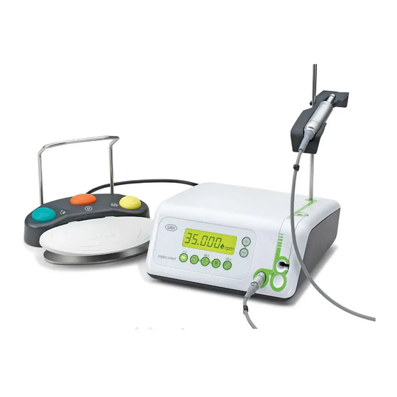
Page 17: Description Of Front Panel
6. Description of front panel Program buttons Pump arm Display Stand holder Pump arm OPEN Motor connection socket... -
Page 18: Description Of Rear Panel
7. Description of rear panel Stand holder Connecting socket for foot control Power socket Fuse holder with 2 fuses REF 06661800 (2 x 250 V – T1.25AH) Power switch ON / OFF... -
Page 19: Description Of Foot Control
8. Description of foot control Handle ORANGE attach / detach Change program Programs 1 to 4 and torque steps 20 – 60 Ncm in program 5 GREEN Pump ON / OFF YELLOW Change motor direction forward / reverse drive GREY Start motor (pedal) VARIABLE or ON / OFF (Factory setting = variable) -
Page 20: Description Of Motor With Cable
9. Description of motor with cable The motor with cable must not be disassembled. The motor with cable must not be oiled (lubricated for life). To prevent the instrument on the motor attachment from turning during transmission of high torques, the locking pin supplied can be pushed into the designated hole (see illustration). -
Page 21: Starting Operation - General
10. Starting operation – General Always place the Implantmed on a flat level surface. Ensure that the Implantmed can be disconnected easily from the power supply. Connect the mains cable and Attach the motor support foot control. and lock it. Pay attention to the positioning! ... -
Page 22: Switch On / Switch Off Implantmed
11. Switch on / switch off Implantmed Switch on Implantmed Switch off Implantmed Connect the Implantmed to the Turn the Implantmed off at the power supply. power switch. Turn the Implantmed on at the Disconnect the Implantmed power switch. - Page 23 12. Control unit operation – Changing program (P1 – P5) Activate the desired program (P1 – P5) by pressing the corresponding program button. During selection an audible signal can be heard and the Program button lights up. The selected program appears on the display with the adjusted range in rpm, e.g. for P1: Pump operation ON / OFF Display settings...
-
Page 24: Control Unit Operation
Control unit operation – Changing speed (P1 – P3) Pressing and holding PLUS / MINUS depressed activates the repeat function and the values are continuously increased / decreased. Press program button (P1 – P3) Increase speed Decrease speed The accuracy of the set speed in the range 300 –... - Page 25 Control unit operation – change torque (P4 – P5) Program P4: range from 5 – 70 Ncm, intermediate stage 32 Ncm. Program P5: range from 20 – 60 Ncm. Pressing and holding PLUS / MINUS depressed activates the repeat function and the values are continuously increased / decreased.
- Page 26 Control unit operation – change coolant flow rate (P1 – P5) Factory setting 100 %. Adjustable range 65 %, 80 % and 100 %. Press and hold the PLUS / MINUS button to continuously increase or decrease the values. Keep program button P2 depressed throughout this procedure. ...
-
Page 27: Foot Control Operation
13. Foot control operation Change program Press the ORANGE button to select programs 1 – 4 and torque steps (20 – 60 Ncm) in program 5 in ascending order. A longer confirmation signal is heard on changing from program 4 to program 1 or 60 Ncm to 20 Ncm setting in program 5. With each program change, the motor direction is automatically set to forward operation. -
Page 28: Foot Control Operation
Foot control operation To change from VARIABLE to ON / OFF Keep program button P3 depressed throughout this procedure. Keep P3 depressed for approx. 4 seconds Continue to keep P3 depressed and simultaneously press the PLUS and MINUS buttons Continue to keep P3 depressed and set the adjusting. - Page 29 14. Reset factory settings The factory setting always starts with program 1 (P1). Switch off control unit Keep P1 depressed and simultaneously switch on the control unit...
-
Page 30: Factory Settings
Factory settings (P1 – P3) Transmission ratio 20:1 20:1 Speed rpm 35,000 1,200 Adjustable range rpm 300 – 40,000 15 – 2,000 15 – 2,000 Motor direction forward forward forward Pump Torque Ncm 100% 100% 100%... - Page 31 Factory settings (P4 – P5) P4 forward P4 reverse P5 forward P5 reverse Transmission ratio 20:1 20:1 20:1 20:1 Speed rpm Motor direction forward reverse forward reverse Pump Torque Ncm Adjustable range Ncm 5 – 70 5 – 70 20 – 60 20 –...
-
Page 32: Thread Cutter Function (Chip Breaker Mode)
15. Thread cutter function (chip breaker mode) When the thread cutter function (P5) is activated, the speed in both forward and reverse operation modes is 20 rpm and can no longer be changed. When the foot pedal (grey) on the foot control is pressed, the thread cutter rotates inwards until the set torque is reached. -
Page 33: Error Messages
16. Error messages Error no. Description Solution Switch off device, allow device to cool for at least Electronics overheating–Safety shutdown 10 minutes, re-start Switch off device, allow device to cool for at least Electronics overloaded 10 minutes, re-start Foot control error – Switch off device, re-start, do not actuate initializing foot control when switching on... - Page 34 17. Hygiene and maintenance Follow your country-specific directives, standards and guidelines for cleaning, disinfection and sterilization. > Wear protective clothing. > Clean and disinfect the motor immediately after every treatment! > Sterilize the motor following cleaning and disinfection. > Sterilize motor with cable and motor support prior to every use. >...
-
Page 35: Hygiene And Maintenance
Hygiene and maintenance Motor with cable Do not twist or kink the motor cable! Do not coil it too tightly! Pre-disinfection > If heavily soiled, clean first with disinfectant cloths. Only use disinfectants that have no protein-fixing effects. - Page 36 Hygiene and maintenance Motor with cable Manual cleaning > Rinse and brush off under demineralized water (< 38 °C / < 100 °F) > Remove any liquid residues (absorbent cloth, blow dry with compressed air). Do not place the motor with cable in liquid disinfectant or in an ultrasonic bath. Manual disinfection >...
- Page 37 Hygiene and maintenance Motor with cable Mechanical cleaning and disinfection internal and external The motor with cable can be cleaned and disinfected in a thermo washer disinfector. W&H permits preparation in a thermo washer disinfector with a drying program. > Follow the manufacturer’s recommendations for devices, cleaning and rinsing agents. Ensure that the motor with cable is completely dry internally and externally after thermo washer disinfection.
- Page 38 Hygiene and maintenance Motor with cable Sterilization and storage W&H recommends sterilization according to EN 13060, class B Other sterilization methods may reduce the life span of your motor. For USA and Canada: Hospital grade sterilization with pre and post vacuum cycle. >...
- Page 39 Hygiene and maintenance Approved sterilization procedures Follow your country-specific directives, standards and guidelines. > Steam sterilization class B with sterilizers in accordance with EN 13060. Sterilization holding time a minimum of 3 minutes at 134 °C. > Steam sterilization class S with sterilizers including drying program in accordance with EN 13060. The sterilizer manufacturer must give its express approval for the sterilization of motors.
-
Page 40: W&H Accessories
Use only original W&H accessories/spare parts 18. W&H Accessories or accessories approved by W&H 04013500 04013600 04541900 Sterilization cassette Transportation case Trolley, white 04542100 Trolley, white with power sockets 04006800 Locking pin 06177800 04005900 06661800 Motor support Stand Fuse (250 V - T1.25AH) -
Page 41: W&H Accessories
W&H Accessories 06631600 06202400 04653500 Motor with 1.8 m cable Foot control S-N1 Handle incl. 5 clips for foot control S-N1 04363600 04719400 04019000 Irrigation tubing 2.2 m (6 pcs) Irrigation tubing 2.2 m Clips (5 pcs) -
Page 42: Servicing
19. Servicing Regular checking of Implantmed and accessories Regular servicing of function and safety including the accessories is necessary and should be carried out at least once every three years, unless shorter intervals are prescribed by law. The inspection must be undertaken by a qualified organization and must include the following procedures: >... -
Page 43: Servicing
Servicing Motor with cable The standard ISO 11498 stipulates a durability of at least 250 sterilization cycles. In the case of the motor with cable from W&H, we recommend you to have a regular service carried out after 500 sterilization cycles or one year. Repairs If a defect occurs, always return all the equipment, because motor malfunctions an inspection of the electronic controls is also necessary. -
Page 44: Technical Data
20. Technical data Implantmed SI-923 SI-915 Supply voltage: 220 –240 V 100 –130 V Permitted voltage fluctuation: ± 10 % ± 10 % Nominal current: 0.1 –0.8 A 0.2 –1.7 A Frequency: 50 –60 Hz 50 –60 Hz Mains fuse: 2x 250 V –... - Page 45 Technical data Classification according to Paragraph 5 of the General Specifications for the Safety of Medical Electrical Equipment according to IEC 60601-1 / ANSI/AAMI ES 60601-1 Class II equipment Type B applied part (not suitable for intracardiac application) The foot control REF 06202400 conforms to Class AP according to IEC 60601-1 / ANSI/AAMI ES 60601-1 in danger zone M The foot control is water-tight according to IPX8, 1 m depth of immersion, 1 hour (water-tight in accordance with IEC 60529)
-
Page 46: Recycling And Disposal
21. Recycling and disposal Recycling W&H considers that it has a special duty towards the environment. Implantmed along with its packaging has been designed to be as environmentally friendly as possible. Disposal of Implantmed (control unit), foot control and motor Follow your country-specific laws, directives, standards and guidelines for the disposal of used electrical devices. -
Page 51: Explanation Of Warranty Terms
Ex p la n a t ion of w ar r anty te rms This W&H product has been manufactured with great care by highly qualified specialists. A wide variety of tests and controls guarantee faultless operation. Please note that claims under warranty can only be validated when all the directions in the instructions for use have been followed. -
Page 52: Authorized W&H Service Partners
Authorized W&H service partners Find your nearest W&H service partner at http://wh.com Simply go to the menu option »Service« for full details. Alternatively please contact: W&H (UK) LIMITED, 6 Stroud Wood Business Centre, Park Street, St Albans, Herts AL2 2NJ, United Kingdom t + 44 1727 874990, f + 44 1727 874628, E-Mail: technical.uk@wh.com W&H Impex Inc., 6490 Hawthorne Drive, Windsor, Ontario, N8T 1J9, Canada t + 1 800 2656277, + 1 519 9446739, f + 1 519 9746121, E-Mail: service.ca@wh.com... - Page 54 Manufacturer W&H Dentalwerk Bürmoos GmbH Ignaz-Glaser-Straße 53, 5111 Bürmoos, Austria Form No. 50731 AEN t +43 6274 6236-0, f +43 6274 6236-55 Rev. 003 / 30.05.2014 office@wh.com wh.com Subject to alterations...
Need help?
Do you have a question about the implantmed SI-923 and is the answer not in the manual?
Questions and answers
Error message 00 I was trying off the switch but the same error message 00
Error message 00 for the W&H SI-923 means the electronics have overheated, triggering a safety shutdown. The solution is to switch off the device, allow it to cool for at least 20 minutes, and then restart it.
This answer is automatically generated