Table of Contents
Advertisement
Advertisement
Table of Contents

Subscribe to Our Youtube Channel
Related Manuals for W&H Implantmed Plus SI-1010


Summary of Contents for W&H Implantmed Plus SI-1010
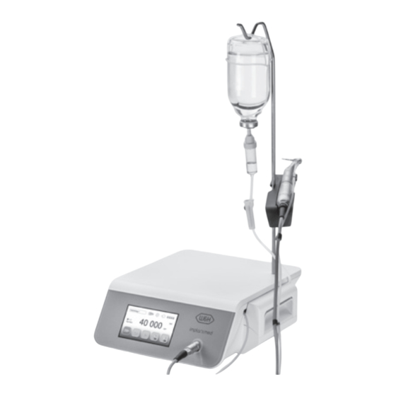
- Page 1 Instructions for Use SI-1010 / SI-1015 / SI-1023...
-
Page 2: Table Of Contents
Contents Symbols .......................................... 4 1. Introduction ....................................... 9 2. Electromagnetic compatibility (EMC) ..............................11 3. Unpacking .........................................12 4. Scope of delivery ......................................13 5. Safety notes ......................................14 6. Description........................................21 of front panel ......................................21 of rear panel ......................................22 of foot control S-N2/S-NW .................................. 23 of motor with cable ..................................... - Page 3 Contents 12. Hygiene and maintenance..................................51 General notes ...................................... 51 Limitations on processing .................................. 52 Initial treatment at the point of use ..............................53 Manual cleaning ....................................54 Manual disinfection .................................... 55 Automated cleaning and disinfection ............................... 56 Drying ........................................57 Inspection, maintenance and testing ...............................
-
Page 4: Symbols
Symbols in the Instructions for Use WARNING! ATTENTION! General explanations, (if persons could be injured) (if property could be damaged) without risk to persons or property Thermo washer disinfectable Sterilizable Call customer service up to the stated temperature... - Page 5 Symbols on the control unit Follow Instructions for Use Class II equipment Catalogue number Consult Instructions for Use Foot control Serial number Date of manufacture On / Off Supply voltage of the control unit Do not dispose of with Electric fuse Alternating current domestic waste Data Matrix code...
- Page 6 Symbols on the foot control CE marking Non-ionizing electromagnetic Catalogue number with identification number radiation XXXX of the Notified Body Do not dispose of with Battery compartment closed Serial number domestic waste Data Matrix code Battery compartment open Date of manufacture for product information including UDI (Unique Device Identification)
- Page 7 Symbols on the packaging CE marking Data Matrix code with identification number for product information including UDI XXXX of the Notified Body (Unique Device Identification) This way up Data structure in accordance with Health Industry Bar Code Fragile, handle with care Temperature limitation +70 °C (+158°F) Max.
- Page 8 Symbols on the irrigation tubing set Consult Instructions for Use Not for re-use Latex-free CE mark Use by Sterilization with with identification number ethylene oxide XXXX of the Notified Body Batch code Caution! According to Federal law, this medical device may only be sold by or on the order of a dentist, physician or any other medical practitioner licensed by the law of the State in which he or she practices and intends to use or order the use of this medical device.
-
Page 9: Introduction
1. Introduction For your safety and the safety of your patients These Instructions for Use explain how to use your product. However, we must also warn against possible hazardous situations. Your safety, the safety of your team and, of course, the safety of your patients, are of paramount importance to us. Observe the safety notes. - Page 10 Introduction Production according to EU Directive The medical device complies with the regulations of Directive 93/42/EEC. Responsibility of the manufacturer The manufacturer can only accept responsibility for the safety, reliability and performance of the medical device when compliance with the following instructions is ensured: >...
-
Page 11: Electromagnetic Compatibility (Emc)
2. Electromagnetic compatibility (EMC) Medical electrical device is subject to particular precautions with regards to EMC and must be installed and put into operation in accordance with the EMC notes included. W&H only guarantees compliance of the device with the EMC Directives when it is used with original W&H accessories and spare parts. -
Page 12: Unpacking
3. Unpacking Remove the packaging. Remove the foot control, Instructions for Use and accessories. Remove the motor with cable. Lift out the insert with the control unit. Remove the mains cable, irrigant support, universal support, irrigation tubing set and Instructions for Use. -
Page 13: Scope Of Delivery
4. Scope of delivery SI-1023 (230V) SI-1015 (120V) SI-1010 (100V) Control unit 30288000 30289000 30290000 Irrigation tubing set 2.2 m REF 436360 (3 pcs, disposable) REF 07721800 Universal support REF 04005900 Irrigant support Mains cable country-specific Optional included in set EM-19 LC motor with electrical REF 30281000 contacts and 1.8 m cable... -
Page 14: Safety Notes
5. Safety notes Control unit / Motor > Before using the medical device for the first time, store it at room temperature for 24 hours > Check the medical device and the motor with cable for damage and loose parts every time before use. >... - Page 15 Safety notes Control unit > Use only original W&H fuses. > Never touch the patient and the electrical connections on the control unit simultaneously. > Make sure that no computer viruses are transferred to the control unit by an external data medium (USB stick). The connection of a USB hard drive with an external power source is not permitted.
- Page 16 Safety notes Control unit / Motor Mains cable / Power switch > Only use the mains cable supplied. > Plug the mains cable only into an earthed power socket. > Set up the control unit so the power switch and the socket are easily accessible at all times. Disconnect the control unit from the power supply in case of danger.
- Page 17 Safety notes Control unit / Motor / Foot control Risks due to electromagnetic fields The functionality of implantable systems, such as cardiac pacemakers and implantable cardioverter defibrillator (ICD), can be affected by electric, magnetic and electromagnetic fields. > Find out if patient and user have implanted systems before using the medical device and consider the application. >...
- Page 18 Safety notes Coolant supply The medical device is designed for use with physiological saline solution. > Always ensure correct operating conditions and that sufficient and adequate coolant is delivered. > Always provide sufficient coolant and ensure the appropriate suction. > Use only suitable coolants and follow the manufacturer’s medical data and instructions. >...
- Page 19 Safety notes Transmission instrument > Follow the directions and safety notes in the Instructions for Use of the transmission instrument. > Only use transmission instruments with an ISO 3964 (DIN 13940) compatible coupling system and manufacturer approved transmission instruments. > Follow the directions of the manufacturer of transmission instrument with reference to transmission ratio, maximum speed and maximum torque.
- Page 20 Safety notes Hygiene and maintenance prior to initial use > Clean and disinfect the control unit, the motor with cable, the universal support and the irrigant support. > Sterilize the motor with cable and the universal support. Test run Do not hold the motor with transmission instrument at eye level. >...
-
Page 21: Description
6. Description of front panel Irrigant support locator Pump cover Display (touchscreen) Pump cover OPEN Connection for motor... -
Page 22: Of Rear Panel
Description of rear panel Irrigant support locator Connection for foot control Power switch ON/OFF Fuse holder with 2 fuses Connection for (2 x 250 V – T1.6 AH) mains cable... -
Page 23: Of Foot Control S-N2/S-Nw
Description of foot control S-N2/S-NW Locator ORANGE attach/detach Change program GREEN Pump YELLOW ON/OFF Change motor direction Forward operation/reverse operation GREY Start motor (pedal) VARIABLE or ON/OFF (Factory setting = variable) - Page 24 Description of foot control S-N2/S-NW ORANGE S-N2 / S-NW: Change program Press the ORANGE button to change programs in ascending order. The motor direction is automatically set to forward operation every time the program is changed. When changing from the last program to the first program a longer acoustic signal sounds (risk of injury). ORANGE S-NW: Switching between multiple control units Press the ORANGE button for 3 seconds...
-
Page 25: Of Motor With Cable
Description of motor with cable The motor with cable must not be disassembled! The motor with cable must not be oiled (pre-oiled for entire service life)! The motor with cable is a type B applied part (not suitable for intracardiac application). Temperature information Temperature of the motor on the operator side: max. -
Page 26: Start-Up
7. Start-up Place the medical device on a flat level surface. Ensure that the medical device can be disconnected from the power supply at any time. Connect the mains cable and Attach the universal foot control. support and lock it. S-N2 Pay attention to the positioning! -
Page 27: Control Unit
8. Control unit switching on and off Switching on the control unit Switching off the control unit Plug the mains cable into an Switch off the control unit at earthed power socket. the power switch. Switch on the control unit ... -
Page 28: Starting Operation
9. Starting operation Setup wizard The touch screen must only be touched using fingers. Using hard objects on the touch screen may scratch or damage the surface. Setting up control unit Switch on your control unit and follow the directions of the setup wizard. The set-up wizard guides you through the various set-up stages up to the main menu: >... -
Page 29: Control Unit Operation
10. Control unit operation Main menu My favorites Set program Documentation / Wi-Fi Pairing Set speed / torque Setup Foot control Forward/reverse operation mode ... - Page 30 Control unit operation My favorites Select drill protocol group An activated drill protocol cannot be deleted Edit > Adjust factory setting of drill protocol groups. > Create drill protocol Copy Rename Activate Delete...
- Page 31 Control unit operation Set program max. 50 Ncm Transmission Speed At 40,000 rpm the accuracy of the set speed is ±10 %. Torque Adjustment range 5 – 80 Ncm with WI-75 and WS-75 only. The motor switches off automatically when the set torque is reached in forward and reverse operation modes. The accuracy of the set torque in the 20 –...
-
Page 32: Menue Navigation
Control unit operation Menue Navigation... - Page 33 Control unit operation User Torque curve An activated user cannot be deleted Set screen lock Add user Activating / deactivating screen lock Screen lock Manage user User settings: Copy, Rename, Activate, Delete Interval Interval: Select time Foot control Activating / deactivating LED Pairing –...
- Page 34 Control unit operation System check Wi-Fi-dongle Test run Dental numbering system Device info Select dental numbering system: FDI / UNS FDI (Féderation Dentaire Internationale = Service International dental numbering system) UNS (Universal Numbering System = Licenes American dental numbering system) GPL: GNU General Public License LGPL:...
- Page 35 Control unit operation Foot control Beacon Software update Beacon Pairing Reset Wi-Fi pairing Reset Restore factory settings Restart Control unit restarts automatically Import user settings Export user settings...
- Page 36 Control unit operation Confirm/save Drill function Favorite selected Drill function black = information Drill function green = Information with selection option red = error message, work cannot be continued Thread-cutter function orange = error message, work can be continued Implantatinsertion red = replace batteries Implant stability quotient measurement W&H Osstell ISQ module is available as an...
-
Page 37: Factory Settings
Control unit operation Factory settings Implantology 1 Transmission WS-75 (20:1) WS-75 (20:1) Speed rpm 35,000 1,200 Setting range rpm 200 – 40,000 10 – 2,000 10 – 2,000 Motor direction of rotation forward forward forward Pump Torque Ncm 100 % 100 % 100 %... - Page 38 Control unit operation Factory settings Implantology 1 Transmission WS-75 (20:1) WS-75 (20:1) Speed rpm Setting range rpm 10 – 50 10 – 50 Motor direction forward reverse of rotation Pump Torque Ncm Setting range Ncm 5 – 80 5 – 80...
- Page 39 Control unit operation Factory settings Implantology 2 Transmission WS-75 (20:1) WS-75 (20:1) Speed rpm 35,000 1,200 Setting range rpm 200 – 40,000 10 – 2,000 10 – 2,000 Motor direction of rotation forward forward forward Pump Torque Ncm 100 % 100 % 100 %...
- Page 40 Control unit operation Factory settings Implantology 2 Transmission WS-75 (20:1) WS-75 (20:1) WS-75 (20:1) WS-75 (20:1) Speed rpm Setting range rpm 10 – 50 10 – 50 10 – 50 10 – 50 Motor direction forward reverse forward reverse of rotation Pump Torque Ncm Setting range Ncm...
- Page 41 Control unit operation Factory settings Oral Surgery Transmission 1:2.7 Speed rpm 35,000 10,000 108,000 Setting range rpm 200 – 40,000 200 – 40,000 540 – 108,000 Motor direction of rotation forward forward forward Pump Torque Ncm 100 % 100 % 100 %...
- Page 42 Control unit operation Factory settings Thread-cutter function (chip breaker mode) When the pedal (grey) on the foot control is pressed, the thread cutter rotates inwards until the set torque is reached. The control unit automatically switches to reverse operation when the set torque is reached. Disengaging and then re-engaging the pedal will switch the control unit back to forward operation.
-
Page 43: Documentation With Usb Stick
Control unit operation Documentation with USB stick Drill protocols, torque curves and ISQ values can only be documented in the thread-tapping function, implant insertion or ISQ measurement. Documentation must be activated or deactivated for each program. A USB stick is required to save the documentation. >... - Page 44 Control unit operation Documentation with USB stick Further documentation > Add new position > Start new docu > Complete docu When the motor stops, a diagram appears, which is automatically saved to the USB stick. Edit documentation A text file (csv) and a PDF file are saved on the USB stick. The text file can be opened in Microsoft®...
- Page 45 Control unit operation ioDent platform ® Follow the directions and safety notes in the Instructions for Use of the ioDent® platform. Check the data exchange between the ioDent® platform and the medical device. > Check the transferred data for completeness and correctness. Establishing a connection to the ioDent®...
-
Page 46: Iodent® Platform
Control unit operation ioDent platform ® Connecting the medical device to an IT network or changing an IT network can lead to previously unidentified risks to patients, operators or third parties. The operator of the IT network is responsible for identification, analyzing, evaluating and controlling these risks. -
Page 47: Beacon
Control unit operation Beacon Follow the directions and safety notes in the Instructions for Use for the Beacon. Establishing a connection to the Beacon > Insert the Osstell dongle. Beacon pairing (standard) > Only possible in the ISQ program. > All Beacons connect to the medical device automatically. Beacon pairing using the serial number >... -
Page 48: Error Messages
11. Error messages The error message disappears when it is clocked or when the pedal (grey) on the foot control is released. Icon Description of error Solution WARNING FOOT CONTROL > Check plug contacts of foot control > Check the plug contacts of the dongle WARNING MOTOR >... - Page 49 Error messages Icon Description of error Solution WARNING TIME-OUT > Release the pedal (grey) on the foot control > Allow motor to cool for at least 10 minutes SYSTEM ERROR > Switch the control unit off and back on again If the error message appears again, contact an authorized W&H service partner immediately.
- Page 50 Error messages Icon Description of error Solution WARNUNG CONNECTION > Press the ioDent® Wi-Fi dongle symbol > Attempt to establish a connection with the ioDent® platform again. WARNING DATA RECEPTION > Restart the data transfer on the ioDent® platform. WARNING TIME SYNCHRONISATION >...
-
Page 51: Hygiene And Maintenance
12. Hygiene and maintenance General notes Follow your local and national laws, directives, standards and guidelines for cleaning, disinfection and sterilization. > Wear protective clothing, safety glasses, face mask and gloves. > Use only oil-free, filtered compressed air with a maximum operating pressure of 3 bar for manual drying. Cleaning agents and disinfectants >... -
Page 52: Limitations On Processing
Hygiene and maintenance Limitations on processing The product lifetime and the medical device’s ability to operate correctly are mainly determined by mechanical stress during use and chemical influences due to processing. > Send worn or damaged medical devices and/or medical devices with material changes to an authorized W&H service partner. -
Page 53: Initial Treatment At The Point Of Use
Hygiene and maintenance Initial treatment at the point of use > Clean and disinfect the medical device immediately after every treatment. > Wipe the control unit, the motor with cable, the universal support and the irrigant support with disinfectant. Note that the disinfectant used during pre-treatment is only for personal protection and cannot replace the disinfectant step after cleaning. -
Page 54: Manual Cleaning
Hygiene and maintenance Manual cleaning Motor with cable / Universal support / Irrigant support > Do not immerse the motor with cable, the universal support or the irrigant support in liquid disinfectant or in an ultrasonic bath. Motor with cable / Universal support / Irrigant support >... -
Page 55: Manual Disinfection
Hygiene and maintenance Manual disinfection Motor with cable / Universal support / Irrigant support > W&H recommends wipe-down disinfection. Evidence of the basic suitability of the motor with cable, the universal support and the irrigant support for effective manual disinfection was provided by an independent test laboratory using the »mikrozid® AF wipes« disinfectant (Schülke & Mayr GmbH, Norderstedt). -
Page 56: Automated Cleaning And Disinfection
Hygiene and maintenance Automated cleaning and disinfection Motor with cable / Universal support / Irrigant support W&H recommends automated cleaning and disinfection using a washer-disinfector (WD). Read the notes, follow the instructions and heed the warnings provided by the manufacturers of washer-disinfectors, cleaning agents and/or disinfectants. -
Page 57: Drying
Hygiene and maintenance Drying Motor with cable / Universal support / Irrigant support > Ensure that the motor with cable, the universal support and the irrigant support are completely dry internally and externally after cleaning and disinfection. > Remove any liquid residues using compressed air. -
Page 58: Inspection, Maintenance And Testing
Hygiene and maintenance Inspection, maintenance and testing Inspection – Motor with cable / Universal support / Irrigant support > Check the motor with cable, the universal support and the irrigant support after cleaning and disinfection for damage, visible residual soiling and surface changes. >... -
Page 59: Packaging
Hygiene and maintenance Packaging Motor with cable / Universal support Wrap the motor with cable and the universal support in sterilization packages that meet the following requirements: > The sterilization package must meet the applicable standards in respect of quality and use and must be suitable for the sterilization procedure. -
Page 60: Sterilization
Hygiene and maintenance Sterilization Motor with cable / Universal support W&H recommends sterilization according to EN 13060, EN 285 or ANSI/AAMI ST79. > Read the notes, follow the instructions and heed the warnings provided by the manufacturers of steam sterilizers. >... -
Page 61: Storage
Hygiene and maintenance Storage Motor with cable / Universal support > Store sterile goods dust-free and dry. > The shelf life of the sterile goods depends on the storage conditions and type of packaging. -
Page 62: Servicing
13. Servicing Regular checks Regular servicing of function and safety including the accessories is necessary and should be carried out at least once every three years, unless shorter intervals are prescribed by law. The inspection must be undertaken by a qualified organization and must include the following procedures: Control unit >... - Page 63 Servicing Repairs and returns In the event of operating malfunctions immediately contact an authorized W&H service partner. Repairs and maintenance work must only be undertaken by an authorized W&H service partner. > Ensure that the medical device has been completely processed before returning it. >...
-
Page 64: W&H Accessories And Spare Parts
14. W&H accessories and spare parts Use only original W&H accessories and spare parts or accessories approved by W&H. Suppliers: W&H partners (Link: https://www.wh.com) 04013500 07962790 07721800 Sterilization cassette Transportation case Universal support 04005900 06352200 30281000 Irrigant support Fuse (250 V - T1.6AH) EM-19 LC motor with electrical contacts and 1.8 m cable... - Page 65 W&H accessories and spare parts 30285000 04653500 04719400 Foot control S-N2 Locator for foot control Irrigation tubing set 2,2 m 30264000 Foot control S-NW 04363600 06290600 30185000 Irrigation tubing set 2.2 m (6 pcs) Hose clips (5 pcs) EM-19 motor without electrical contacts and 1.8 m cable...
- Page 66 W&H accessories and spare parts 08026120 08026150 ioDent® gateway mini ioDent® Wi-Fi dongle...
-
Page 67: Technical Data
15. Technical data Control unit SI-1023 SI-1015 SI-1010 Mains voltage: 230 V 120 V 100 V Permissible voltage fluctuation: 220 – 240 V 110 – 130 V 90 – 110 V Rated current: 0.3 – 0.8 A 0.3 – 1.6 A 0.3 –... - Page 68 Technical data Classification according to Paragraph 6 of the General Specifications for the Safety of Medical Electrical Device according to IEC 60601-1/ANSI/AAMI ES 60601-1 Class II medical electrical device (protective earth conductor used for functional earth connection only!) Type B applied part (not suitable for intracardiac application) S-N2 / S-NW are approved for operation in potentially explosive atmospheres.
-
Page 69: Disposal
16. Disposal Ensure that the parts are not contaminated on disposal. Follow your local and country-specific laws, directives, standards and guidelines for disposal. > Medical device > Waste electrical equipment > Packaging... -
Page 70: W&H Course Certificate
W&H course certificate for the user The user has been trained to use the medical device correctly in accordance with the legal regulations (medical devices marketing regulations, medical devices act). Particular attention has been paid to the chapters on safety notes, start-up, operation, hygiene and maintenance, and service (regular inspections). Product name Serial number (SN) Manufacturer with address... - Page 71 W&H course certificate for the instructor The user has been trained to use the medical device correctly in accordance with the legal regulations (medical devices marketing regulations, medical devices act). Particular attention has been paid to the chapters on safety notes, start-up, operation, hygiene and maintenance, and service (regular inspections). Product name Serial number (SN) Manufacturer with address...
-
Page 73: Explanation Of Warranty Terms
Ex p la na ti on o f war ranty ter ms This W&H product has been manufactured with great care by highly qualified specialists. A wide variety of tests and controls guarantees faultless operation. Please note that claims under warranty can only be validated when all the directions in the Instructions for Use have been followed. -
Page 74: Authorized W&H Service Partners
Authorized W&H service partners Visit W&H on the Internet at http://wh.com You can find your nearest authorized W&H service partner under “Service” in the menu. If you do not have Internet access, please contact: W&H (UK) LIMITED, 6 Stroud Wood Business Centre, Park Street, St Albans, Hertfordshire AL2 2NJ, United Kingdom t + 44 1727 874990, f + 44 1727 872254, E-Mail: technical.uk@wh.com W&H Impex Inc., 6490 Hawthorne Drive, Windsor, Ontario, N8T 1J9, Canada t + 1 800 2656277, 1 519 9446739, f + 1 519 9746121, E-Mail: service.ca@wh.com... -
Page 75: Manufacturer's Declaration
Manufacturer’s declaration... - Page 76 Manufacturer’s declaration...
- Page 77 Manufacturer’s declaration...
- Page 78 Manufacturer’s declaration...
- Page 80 Manufacturer W&H Dentalwerk Bürmoos GmbH Ignaz-Glaser-Straße 53, 5111 Bürmoos, Austria Form Nr. 50873 AEN t +43 6274 6236-0, f +43 6274 6236-55 Rev. 005 / 26.04.2019 office@wh.com wh.com Subject to alterations...
Need help?
Do you have a question about the Implantmed Plus SI-1010 and is the answer not in the manual?
Questions and answers
can contaangle handpice be aotoclavble
Yes, the W&H Implantmed Plus SI-1010 contra-angle handpiece is autoclavable. The manual provides recommended sterilization procedures and confirms the device’s suitability for effective sterilization using steam sterilizers.
This answer is automatically generated