Table of Contents
Advertisement
This manual contains proprietary information, which shall not be reproduced or
transferred to other documents or disclosed to others without prior written
Canada: 21800 Ave. Clark Graham, Baie d'Urfé, QC H9X 4B6
Tel: (514) 457-0701
USA:
348 Route 11, Champlain, N.Y. 12919-4816
Tel: (800) 361-6820
Europe: 12 Avenue du Québec, Batiment I 2 Silic 642
91965 Courtaboeuf CEDEX (France)
Tel: 33 (01) 69 18 71 17
KeyPad service manual
Rev.1.1
Copyright 2003 by SCP SCIENCE
All Rights Reserved
permission from
SCP SCIENCE.
Patents Pending
SCP SCIENCE
www.scpscience.com
sales@scpscience.com
MANUFACTURED IN CANADA
CERTIFIED TO
CSA 1010 .1
UL 3101-1
IEC 1010-1
Fax: (514) 457-4499
Fax: (800) 253-5549
Fax: 33 (01) 60 92 05 67
1
Advertisement
Table of Contents

Related Manuals for SCP SCIENCE DigiPREP Series

Summary of Contents for SCP SCIENCE DigiPREP Series
- Page 1 Copyright 2003 by SCP SCIENCE All Rights Reserved This manual contains proprietary information, which shall not be reproduced or transferred to other documents or disclosed to others without prior written permission from SCP SCIENCE. Patents Pending SCP SCIENCE Canada: 21800 Ave. Clark Graham, Baie d’Urfé, QC H9X 4B6...
-
Page 2: Table Of Contents
TABLE OF CONTENTS 1.Introduction Warranty ....................4 1.1 Error Messages ................5 1.2 Basic verification list ................. 6 1.3 Symptoms ..................8 1.4 DigiPREP KeyPad Automatic Diagnostics Test Procedure ....9 1.5 Controller Physical Description ............10 1.6 Instrument Operation ..............11 1.6.1 Set-Up Menu ................ - Page 3 8.5.2 Heater is not heating up ............... 42 9.Part lists 9.1 Controller major part list ..............44 9.2 Heating block major part list............45 10.Service Departement SCP SCIENCE ..................46 11.Index Figures ....................47 12.Electrical Schematic DigiPREP KeyPad ................48 KeyPad service manual Rev.1.1...
-
Page 4: Warranty
1. Introduction This manual is to be used by distributors and employees of SCP SCIENCE only. The DigiPREP KeyPad Controller is used to control the DigiPREP Digestion Systems (Jr, MS, HP, HT). Operation details of the KeyPad can be found in the DigiPREP Digestion System operation manuals or older KeyPad instruction manuals (see references page). -
Page 5: Error Messages
SCP SCIENCE as being relevant to the repair of an instrument and to the improvement of the product. 7. An RMA # is required prior to returning any item to SCP SCIENCE. 8. SCP SCIENCE shall not be responsible for any damage or losses however caused, which may be experienced as a result of the installation or use of this product. -
Page 6: Basic Verification List
1.2 Basic verification list 1. Visual and physical inspection All parts are included (see section 1.5) Voltage selector is at the right position (both block and controller) Power cord is fully inserted All connectors and cables are inserted accordingly ... - Page 7 3. Power Supply The Fuse is fine Power cables are correctly inserted (see section 3) Comments and observations: ________________________________________________________________ ________________________________________________________________ ________________________________________________________________ ________________________________________________________________ ________________________________________________________________ ________________________________________________________________ ________________________________________________ 4. Heater and Monostable Circuit DigiPREP block is connected into the controller ...
-
Page 8: Symptoms
1.3 Symptoms The following symptoms must be verified before going into more detail (see figure 1). 1. The block is over shooting the set point temperature, and the temperature keeps climbing. Check the SSR Relay section 3.1.5 2. The block is not heating ... -
Page 9: Digiprep Keypad Automatic Diagnostics Test Procedure
1.4 DigiPREP KeyPad Automatic Diagnostics Test Procedure The CPU is able to perform an automatic diagnostic test. Follow the 7 simple steps below. Shut off power to the DigiPREP KeyPad. Ensure voltage selector is switched to the correct position. NOTE: The selector switch shows the voltage selected in white text. -
Page 10: Controller Physical Description
1.5 Controller Physical Description DigiSET dongle Detachable Power Cord Figure 2: DigiPREP KeyPad controller physical diagram 1. LED – Visible indication that DigiPREP KeyPad Controller is powered-up. 2. Digital Display Screen (LCD) 3. KeyPad – Input all data into controller. 4. -
Page 11: Instrument Operation
Connect the power cord to the back of the controller. You are now ready to plug the system into the appropriate wall receptacle. This banner screen will change to the Menu screen after a 5 second delay. SCP SCIENCE DigiPREP Jr. 1.6.1 Set-Up Menu The Menu screen allows for operating the system or changing the menu language. -
Page 12: Language Selection
< > keys move the blinking curser to the ‘Operation’ mode or the Using the ‘Utilities‘ mode Press 1.6.2 Language Selection UTILITIES VER X.X < > Using the keys move the blinking curser to the language of choice. The ... -
Page 13: Setting The Timer
1.6.5 Setting the Timer TARGET TIME? 0 TO 999 XXX Enter the required ‘Target Time’ (minutes). The Target Time is the required time at the designated Target Temperature. To change the Target Time, use the numeric keypad and over write with the desired value. ... - Page 14 Figure 4: KeyPad display mounting view. Legend: 1. Rounded-Head Nylon Screw #6-32 x 1” 2. On/Off Switch 3. Dongle 2-Pin Female 4. Panel Lock Nut 5. Panel Mount Connector 7-Pin Male 6. Panel Mount Connector 2-Pin Male KeyPad service manual Rev.1.1...
- Page 15 7. Flat Head Nylon Screw #6-32 X 1 “ 8. Voltage Selector Switch 9. Flat Washer, Nylon #6 Screw 10. LED 11. Nylon Nut #6-32 12. Stud #6-32 13. Brass Insert #6 Screw 14. LCD 15. Fish Paper 16. Nylon Stand-off #6-32 x ¼” 17.
-
Page 16: Controller General Description
1.7 Controller General Description The following figure shows a general block diagram of the KeyPad controller and all the interaction between components. Each part will be explained in detail in a different section of the document. + 5V (to all circuit) POWER MODULE To Heater (Ext.) HEATER CIRCUIT... -
Page 17: Light Emitting Diode (Led) & Lcd
2. Light Emitting Diode (LED) & LCD Ensure the voltage selector switch is set at the proper voltage for your location before powering the controller (see Figure 2). It is typical set at 230 volts when it leaves the factory. 2.1 Operation LED not illuminated (blue) when power is on ... -
Page 18: Digital Screen Backlight Is Not Working
If the LED is not lit, please refer the Power Circuit section and the CPU section before changing the LED. NOTE: Ensure that the LED has not been connected in reverse, positive to negative. 2.2 Digital Screen Backlight is not working ... -
Page 19: Digital Screen (Lcd) Is Malfunctioning
(see figure 2) With the system powered up, verify that the following message is appearing for 5 seconds on the LCD screen: SCP SCIENCE DigiPREP If the startup message is not appearing or strange character are displayed o Replace the LCD monitor ... -
Page 20: Keypad Malfunction
3. KeyPad Malfunction The KeyPad is made of 16 independent switches. The information of a pressed button is sent to the CPU with help of a row and column detector. One should feel a ‘click’ upon pressing a button. If there is no click then the PCB board adjustment should be checked. -
Page 21: Keypad Diagnostic Section
Press the LEFT ARROW key a couple of time and see if the cursor switched from ON to OFF and so on. Press the RIGHT ARROW key a couple of time and see if the cursor switched from ON to OFF and so on. ... -
Page 22: Specific Button Problem
4 5 6 Figure 10: Keypad resistors location Legend: 1. R16 2. R11 3. R18 4. R12 5. R13 6. R14 7. R19 8. R20 3.2.2 Specific Button Problem If only different row or column buttons are in trouble: First, verify the impedance of the button (see figure 11) by measuring between 1 and 2 of each faulty buttons: ... - Page 23 Figure 11: Push button measuring location Legend: 1. Alarm button 2. Button #3 3. Button #2 4. Button #1 5. Temperature setting button 6. Button #6 7. Button #5 8. Button #4 9. Time setting button 10. Button #9 11. Button #8 12.
-
Page 24: Power Section
4. Power Section The power section is rectifying and regulating power for all different parts of the KeyPad Controller. It is mainly composed of a transformer, a bridge diode and a DC regulator. FUSE regulator 2200uF 0.1uF Figure 12: AC/DC converter Ensure the voltage selector switch is at the correct position before powering the controller (see Figure 2) 4.1 The controller is not functioning when power switch is on... - Page 25 Figure 13: Power connections Legend: 1. FUSE, 05A AWG 2. QD3 3. QD2 4. QD1 o Use a multimeter to measure the following voltages (see 14 for parts location): Locate diode D4 and D1 cathodes and measure the transformer output power between D4 cathode and D1 anode (should be between 8V and 9.5V AC).
- Page 26 Figure 14: Diodes and regulator location Legend: 1. Diode 1 2. Diode 5 3. Diode 2 4. Diode 4 5. U2 pin 3 6. U2 pin 2 7. U2 pin 1 KeyPad service manual Rev.1.1...
-
Page 27: Heater And Monostable Section
5. Heater and Monostable Section This circuit controls the heater inside all types of DigiPREP Blocks. It consists of a Solid State Relay, a Monostable Multivibrator and protection circuit. Base Frequency Setting Solid State Relay Monostable Multivibrator Trigger input Pin 12 from CPU COM2 To Heater... -
Page 28: Internal Wiring Connection Verification
Figure 16: DigiSET connector location Legend: 1. DigiSET connector 5.1.3 Internal wiring connection verification After removing the bottom plate, verify the connectivity between the heating block external connector and the PCB. 5.1.4 DigiSET verification (only if available) Make sure that the DigiSET is fully functional and that the voltage selector is properly set (see DigiSET operation and service manual). - Page 29 Monostable verification (74HC123AN – U3) NOTE: This will also confirm that the CPU is also up and running o Unscrew the bottom plate by removing the four screws holding the feet in place. o First verify that U3 part number is 74HC123AN. If not, please replace accordingly (see figure 18).
- Page 30 If the LED is not ON, if possible, use an oscilloscope and see if there is a pulsing signal on the trigger input, coming from the CPU. The pulse width should always be 1 second regardless of the frequency (please refer to the figure 15 and figure 18 for pin location).
- Page 31 o Measure with a multimeter the voltage between T2 test point and GND Jumper (analog ground). o If there is a pulse or a steady 5V then the Q3 switch is fine. The problem is probably the solid-state relay. o If there is always 0V and the LED is ON or toggles, then replace Q3.
- Page 32 0 Volt Figure 20: SSR output when heating section is firing NOTE: if all of those tests are correct, please refer to the DigiPREP heating Block section for more detail (see section 8). KeyPad service manual Rev.1.1...
-
Page 33: A/D Converter
6. A/D Converter The analog to digital conversion is the feedback information coming from the heater block temperature sensors or from a DigiPROBE. The CPU section handles this information in order to control the temperature of the heating block. 6.1 Possible A/D problem ... -
Page 34: A/D Power And Connections
6.1.2 A/D power and connections With the help of a multimeter, make sure that the A/D (U9) is powered (see figure 22 for pin 15 and 16 location). If it is not powered up, then the 5V regulator (U7) part is not functioning correctly. ... -
Page 35: Cpu Section
7. CPU Section The CPU section is in fact the daughter card that fits directly on the KeyPad controller PCB (see figure 23 for location). Figure 23: CPU daughter card location Legend: 1. CPU daughter card 2. Battery backup If any of the sections 1 to 4 has been verified and a CPU problem is suspected then try the following sections. -
Page 36: Power Led Malfunction
7.2 Power LED malfunction If the power LED is not correctly functioning and the section 1 has been fully verified: Verify the battery and the socket integrity (see figure 23 for location): Part must be replaced and the preprogrammed setup must be reentered if the battery is bad. -
Page 37: Digiprep Blocks
8. DigiPREP Blocks DigiPREP Jr. Block description DigiPREP Jr. 24 position Digestion Block DigiSET dongle DigiPROBE dongle One (1) - 24 Position DigiTUBE Racks 1. DigiPROBE Connector – Connection port for DigiPROBE. DigiPROBE will allow direct monitoring and control based on actual sample temperature. DigiPROBE Dongle must be installed to run the DigiPREP Jr. -
Page 38: Digiprep Ms Block Description
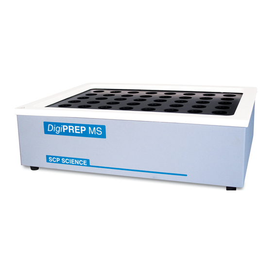
7. DigiPROBE Storage Well – Use with replaceable glass liner. 8. Voltage Selector Switch - Select appropriate voltage. If 115 V is showing, system is running at 115 volts. 8.2 DigiPREP MS Block Description DigiPREP MS 48 position Digestion Block DigiSET dongle DigiPROBE dongle Two (2) - 24 Position... -
Page 39: Digiprep Hp Block Description
5. DigiPREP Controller – DigiPREP MS is designed to be used with DigiPREP KeyPad* or Touch Screen* controller (*Sold separately). 6. DigiPROBE well – Use with replaceable glass liner. 7. Voltage Selector Switch - Select appropriate voltage. If 115 V is showing, system is running at 115 volts. -
Page 40: Digiprep Ht Block Description
6. DigiPROBE well – Use with replaceable glass liner. 7. Voltage Selector Switch - Select appropriate voltage. If 115 V is showing, system is running at 115 volts. 8.4 DigiPREP HT Block Description DigiPREP HT Digestion Block 1. Exhaust Manifold Module. 2. -
Page 41: Heater Verification
8.5 Heater verification The following figure shows the heater general diagram. PROBE Dongle for Controller DigiPROBE internal RTD Conn. 1 2 3 4 to metal support and graphite block GND (Earth) AC (Hot) AC (Neutral) Thermal Switch 180degC (Jr/MS/HP) or gaz switch (HT) Heating Pad Figure 24: Heater general diagram... -
Page 42: Digiprobe Error
Figure 25: Heating Block internal connection 8.5.1 DigiPROBE error If the dongle is put into its socket (COM2), the RTD (temperature sensor) is faulty. Please open the block and make sure that the impedance of the RTD is 108 ohms. ... - Page 43 Figure 26: Heating Block Parts Legend: 1. Thermal Switch 180 C 2. Voltage selector (115V-230V) 3. Heater pad 4. Graphite block 5. RTD (thermal sensor) Models Voltage Resistance DigiPREPHP 230 V 30 115 V 60 DigiPREP Jr. 230 V 50 115 V 100...
-
Page 44: Part Lists
9. Part lists 9.1 Controller major part list Part Description Manufacturer number Number Fuse, 0.5A, 250V, Fast blow, 1/4x1 E296 AGC-1/2 E239 Voltage selector 83710030 Switchcraft Panel Mt. 2 Pin Male E225 EN3P2M Switchcraft Cord, 2 Pin Female E226 EN3C2F E287 Buzzer, Piezo PKB24SPC-3601... -
Page 45: Heating Block Major Part List
9.2 Heating Block major part list Part Description Manufacturer number Number Thermo Fuse with 12" Black Si W137 75M180NC Leads C176 S17624PDXT40B Voltage selector switch E239 83710030 Jr., MS, HP, HT Umbilical cord with E767 connector and strain relief MS – HP Heater Dual Voltage E391 M20612RG04 Heater HT, for 100 and 250... -
Page 46: Service Departement
10.Service Department Please phone your local service representative and report this information before returning the product. This will help our technicians determine the cause of the malfunction more quickly. SCP SCIENCE Within North America: Outside North America: Tel: (800) 361-6820... -
Page 47: Index
11. INDEX Figure 1 : Symptoms vs. document references ........8 Figure 2 : DigiPREP KeyPad controller physical diagram ..... 10 Figure 3 : KeyPad layout ..............11 Figure 4 : KeyPad displsy mounting view ..........14 Figure 5 : General KeyPad block diagram ..........16 Figure 6 : LED cable position .............. -
Page 48: Electrical Schematic Digiprep Keypad
KeyPad service manual Rev.1.1... - Page 49 KeyPad service manual Rev.1.1...
Need help?
Do you have a question about the DigiPREP Series and is the answer not in the manual?
Questions and answers