Table of Contents
Advertisement
Quick Links
Advertisement
Table of Contents

Related Manuals for AVer CL01


Summary of Contents for AVer CL01
- Page 1 PTZ Camera Controller User Manual...
- Page 2 The information contained in this documentation is subject to change without notice. In no event will AVer Information Inc. be liable for direct, indirect, special, incidental, or consequential damages arising out of the use or inability to use this product or documentation, even if advised of the possibility of such damages.
- Page 3 COPYRIGHT ©2019 AVer Information Inc. All rights reserved. All rights of this object belong to AVer Information Inc. Reproduction or retransmission in any form or by any means without the prior written permission of AVer Information Inc. is prohibited. All information or specifications are subject to change without prior notice.
-
Page 4: Table Of Contents
Contents Product Introduction ....................1 Overview ......................1 Dimensions ...................... 2 Connections ......................3 Function Buttons ..................... 4 PTZ Camera Controller Operation ................7 Menu ....................... 7 System Settings ....................7 COM Settings ....................8 Ethernet Settings ..................... 9... - Page 5 Password Settings ................... 9 VISCA Command List ................... 10...
-
Page 6: Product Introduction
Product Introduction Overview UPGRADE RS422 RS232 DC12V T T R R RS485 Name Function For upgrading the device firmware. Connect to a PC with a micro (1) Micro USB port USB cable to upgrade. (2) RS422/RS485 port For connecting a camera via RS422 or RS485. Please refer the table below for connection. -
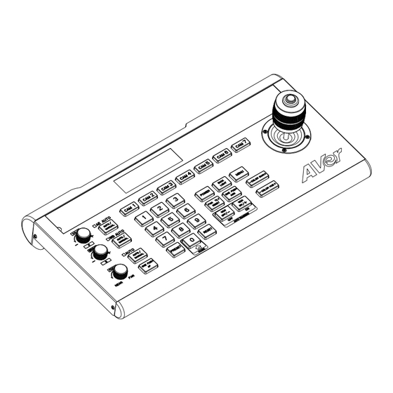
Page 7: Dimensions
Dimensions Unit: mm V A L U E AE AUT O MODE WB A UTO BR IG H T BACK POWER MENU MODE LIGHT TILT A UTO PUSH RESET COLOR GAIN F O C U S A U T O MANUAL OFF/- ON/+... -
Page 8: Connections
Connections All devices must be connected to a power source and turned on. [Note] Please use the power plug that your country supports. We provide four types of power plugs in the package: EU, US, UK, and AU. The PTZ camera controller and the camera must be on the same network ... -
Page 9: Function Buttons
Function Buttons (12) VALUE AE AUTO M ODE (11) WB AUTO BRIGHT BACK POWER MENU MODE LIGHT AUT O TILT PUSH RESET COLOR GAIN FOCUS (10) A U T O MA NUAL OFF/- ON/+ COLOR HUE PU SH PRESET RE S ET NEAR (5) (6) Light sensor... - Page 10 Function Buttons (continued) WB AUTO WB MODE button M ODE For modifying the camera’s white balance VALUE/R BRIGHT/B mode. Press to toggle between the MODE knob knob available modes. The VALUE/R and VALUE/B knobs perform different functions function function in different white balance modes (refer to Auto None None...
- Page 11 Function Buttons (continued) (10) Camera function buttons (continued) CAM1–CAM7 buttons Press the camera button to activate camera ONE PUSH AWB: Triggers a one-time control (the camera indicator will turn green). white balance adjustment. Each camera button must be set to the WDR OFF/- and Tracking OFF camera’s IP address and port (refer to “PTZ ...
-
Page 12: Ptz Camera Controller Operation
PTZ Camera Controller Operation Menu Press the “MENU” button to enter the menu. Press the “MENU” button again to exit. The main menu is as below shown: System Settings COM settings Ethernet settings Password settings Using the joystick to select and set the parameters in the menu: Enter the submenu, move to the selection, or confirm the selected Right value... -
Page 13: Com Settings
System Settings (continued) Joystick sensitivity Set the joystick sensitivity level – 1–7. The higher the joystick sensitivity is set, the smaller the movement necessary to produce rapid pan/tilt rotation. Auto standby Set the length of idle time before the PTZ camera controller enters standby mode – 1, 2, 5, 10, 20, 30, or 60 minutes. -
Page 14: Ethernet Settings
COM Settings (continued) Baud rate Set the baud rate for the channel (CAM1–CAM7) – 2400, 4800, 9600, 19200, or 38400. Protocol Set the protocol for the channel (CAM1–CAM7) – Visca, SonyVisca, Pelco-P, or Pelco-D. Ethernet Settings Set up the camera’s channel, IP address, and port on the PTZ camera controller. The Ethernet settings menu is as shown below: Channel: CAM1 Cam IP: 192.168.001.100... - Page 15 VISCA Command List Command Set Command Command Packet Comments AddressSet Broadcast 88 30 01 FF Address setting CAM_Power 8x 01 04 00 02 FF Power ON/OFF 8x 01 04 00 03 FF CAM_Zoom Stop 8x 01 04 07 00 FF Tele(Variable) 8x 01 04 07 2p FF p=0 (Low) to 7 (High)
- Page 16 Command Set Command Command Packet Comments CAM_ExpComp 8x 01 04 3E 02 FF Exposure Compensation ON/OFF 8x 01 04 3E 03 FF 8x 01 04 0E 02 FF Exposure Compensation Amount Setting Down 8x 01 04 0E 03 FF CAM_Backlight 8x 01 04 33 02 FF Back Light Compensation ON/OFF...
- Page 17 Specifications I/O port RS422/RS485 port 4-pin terminal RS232 port DB 9-pin male interface LAN port RJ45 female port (All communication ports can function simultaneously.) Power plug JEITA type-4 female Upgrade port Micro USB female port Camera control Max support 255 PTZ cameras Control protocol VISCA , PELCO P/D Display screen...
Need help?
Do you have a question about the CL01 and is the answer not in the manual?
Questions and answers