Table of Contents
Advertisement
Models:
6000TR
6000XLT-CDN
6000ARCH
6000XLS
WARNING: IF THE INFORMATION
IN THESE INSTRUCTIONS IS NOT
FOLLOWED EXACTLY, A FIRE OR
EXPLOSION
CAUSING PROPERTY DAMAGE,
PERSONAL INJURY, OR DEATH.
What to do if you smell gas
This product is covered by one or more of the following patents: (United States) 4,112,913; 4,408,594; 4,422,426; 4,424,792; 4,520,791; 4,793,322;
4,852,548; 4,875,464; 5,000,162; 5,016,609; 5,076,254 5,191,877; 5,218,953; 5,328,356; 5,429,495; 5,452,708; 5,542,407; 5,613,4 87; (Australia)
543790; 586383; (Canada) 1,123,296; 1,297,746; 2,195,264; (Mexico) 97-0457; (New Zealand) 200265; or other U.S. and foreign patents pending.
All manuals and user guides at all-guides.com
MAY
RESULT
Heat-N-Glo
READ THIS MANUAL BEFORE INSTALLING OR
OPERATING THIS APPLIANCE. THIS INSTALL-
ERS GUIDE MUST BE LEFT WITH THE APPLI-
ANCE FOR FUTURE REFERENCE.
WARNING: IMPROPER INSTALLA-
TION, ADJUSTMENT, ALTERATION,
SERVICE OR MAINTENANCE CAN
CAUSE INJURY OR PROPERTY DAM-
AGE. REFER TO THIS MANUAL. FOR
ASSISTANCE OR ADDITIONAL INFOR-
MATION CONSULT A QUALIFIED IN-
STALLER, SERVICE AGENCY, OR THE
GAS SUPPLIER.
This appliance may be installed in an
1.
aftermarket, permanently located,
manufactured (mobile) home, where not
prohibited by local codes.
2. This appliance is only for use with the
type of gas indicated on the rating plate.
This appliance is not convertible for use
with other gases, unless a certified kit is
used.
Installers Guide
1
Advertisement
Table of Contents

Related Manuals for Hearth Technologies Heat-N-Glo 6000TR


Summary of Contents for Hearth Technologies Heat-N-Glo 6000TR
- Page 1 All manuals and user guides at all-guides.com Heat-N-Glo Models: Installers Guide 6000TR 6000XLT-CDN 6000ARCH 6000XLS READ THIS MANUAL BEFORE INSTALLING OR OPERATING THIS APPLIANCE. THIS INSTALL- WARNING: IF THE INFORMATION ERS GUIDE MUST BE LEFT WITH THE APPLI- IN THESE INSTRUCTIONS IS NOT ANCE FOR FUTURE REFERENCE.
-
Page 2: Safety And Warning Information
All manuals and user guides at all-guides.com SAFETY AND WARNING INFORMATION READ and UNDERSTAND all instructions carefully before starting the installation. FAILURE TO FOLLOW these installation instructions may result in a possible fire hazard and will void the warranty. Prior to the first firing of the fireplace, READ the Using Your Fireplace section of the Owners Guide. - Page 3 All manuals and user guides at all-guides.com TABLE CONTENTS...
-
Page 4: Approval Listings And Codes
All manuals and user guides at all-guides.com Approval Listings Appliance Certification and Codes Installers Guide CERTIFICATION MODEL LABORATORY TYPE STANDARD Approvals and Codes Installation Codes High Altitude Installations... -
Page 5: Getting Started
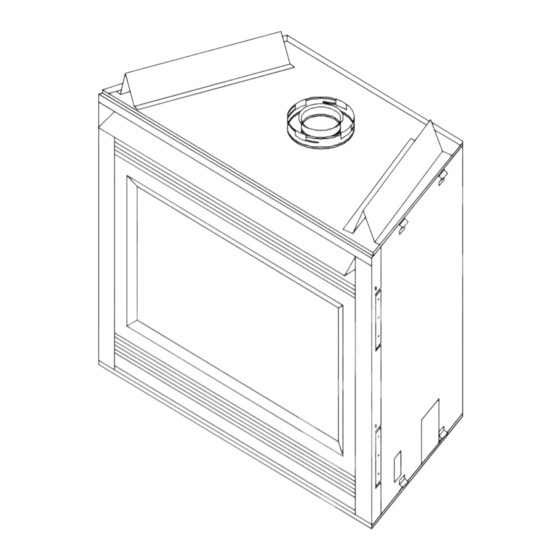
All manuals and user guides at all-guides.com Introducing the Heat-N-Glo Gas Fireplaces Installers Guide Pre-install Getting Preparation Started Installers Guide... - Page 6 All manuals and user guides at all-guides.com NOTE: 6000TR has top and rear collars. 6000XLT-CDN has top collars only. 6000XLS has rear collars only. Left Side Front Right Side...
- Page 7 All manuals and user guides at all-guides.com...
-
Page 8: Step 1 Locating The Fireplace
All manuals and user guides at all-guides.com Step 1 Locating the Fireplace Installing the Fireplace MODEL 6000TR & 37 1/8 52 1/2 74 1/4 6000XLS 6000XLT-CDN 35 1/4 49 3/4 70 3/8 6000ARCH 35 1/4 49 3/4 70 3/8 48 1/4** * SURROUND IN FRONT OF FINISHED WALL ** SURROUND FLUSH WITH FINISHED WALL. -
Page 9: Step 2 Framing The Fireplace
All manuals and user guides at all-guides.com Step 2 Framing the Fireplace CAUTION MEASURE FIREPLACE DIMENSIONS, AND VERIFY FRAMING METHODS AND WALL COVERING DETAILS, BEFORE FRAMING CONSTRUCTION BEGINS. SHOWS CENTER OF12" X 12" VENT FRAMING HOLES FOR TOP & REAR VENTING. Framing should be constructed of 2 X 4 lumber or heavier. -
Page 10: Step 3 Installing The Vent System
All manuals and user guides at all-guides.com Step 3 A. Vent System Approvals Installing the Vent System Installers Guide VENT SYSTEM COMPONENTS VENT SYSTEM TERMINATION KITS... - Page 11 All manuals and user guides at all-guides.com 6-7/16" 6-5/32" (164 mm) (156 mm) 8-1/2" (216 mm) 8-1/2" 11-5/8" 11-1/16" (216 mm) (295 mm) 7-3/8" 5-7/8" (281 mm) 6-1/2" 5-1/16" (187 mm) (149 mm) (165 mm) (129 mm) 8-5/8" (220 mm) 8-5/8"...
-
Page 12: Vertical Venting
All manuals and user guides at all-guides.com VERTICAL VENTING V (FT.) 40' MAX. (12.4 M) NOTE: MUST... -
Page 13: Horizontal Venting
All manuals and user guides at all-guides.com HORIZONTAL VENTING Kit No. Max. Run DVK-01D DVK-01TRD 24" (610 mm) NOTE: Models 6000TR and 6000XLS are tested and approved to use 45° elbows in corner installations. However, 90° elbows will result in better performance. - Page 14 All manuals and user guides at all-guides.com...
- Page 15 All manuals and user guides at all-guides.com FOR 6000TR & 6000XLT-CDN...
- Page 16 All manuals and user guides at all-guides.com H + H 1´ MIN. (305 mm) 2´ MAX. (610 mm) 5´ MAX. (1.52m) 2´ MIN. (610 mm) 4´ MAX. (1.22 m) 10´ MAX. (3.1m) 3´ MIN. (914 mm) 6´ MAX. (1.86 m) 15´...
- Page 17 All manuals and user guides at all-guides.com...
- Page 18 All manuals and user guides at all-guides.com VENTING WITH THREE (3) 90° ELBOWS H + H 1´ MIN. (305 mm) 2´ MAX. (610 mm) 5´ MAX. (1.52 m) 2´ MIN. (610 mm) 4´ MAX. (1.22 m) 10´ MAX. (3.1 m) 3´...
- Page 19 All manuals and user guides at all-guides.com NOTE:...
- Page 20 All manuals and user guides at all-guides.com B. Installing Vent Components For Model 6000TR...
- Page 21 All manuals and user guides at all-guides.com STARTING COLLAR STOVE SEALANT BEAD FIRST VENT COMPONENT 1 INCH (25.4mm)
- Page 22 All manuals and user guides at all-guides.com...
- Page 23 All manuals and user guides at all-guides.com WALL BRACKET WALL STUD 8 FT. (2.4mm) FLUE OUTLET 1 INCH MIN. (25.4mm) NOTE Model DVK-01TRD does not need an exterior firestop on an exterior combustible wall.
- Page 24 All manuals and user guides at all-guides.com TRIM HEAT HEAT SHIELD SHIELD IF TOO LONG, ADD TO SHIELD IF TOO SHORT EXTERIOR FIRESTOP INTERIOR FIRESTOP...
- Page 25 All manuals and user guides at all-guides.com JOIST CEILING NAILS (4 REQUIRED) CEILING FIRESTOP...
- Page 26 All manuals and user guides at all-guides.com JOIST CEILING NAILS (4 REQUIRED) CEILING FIRESTOP C. Vent Termination...
- Page 27 All manuals and user guides at all-guides.com ROUND CAP TERMINATION PERFORATION CANNOT BE INSIDE THE WALL 7 1/2" (191mm) MINIMUM TRAPEZOID CAP TERMINATION 7 1/4" (184mm)
- Page 28 All manuals and user guides at all-guides.com openable fixed closed J or K =VENT TERMINAL 1 2 3 4 1 2 3 4 1 2 3 4 =AREA WHERE TERMINAL IS NOT PERMITTED 1 2 3 4 =AIR SUPPLY INLET 1 2 3 4 30”...
- Page 29 All manuals and user guides at all-guides.com NOTE This also pertains to vertical vent systems installed on the outside of the building.
- Page 30 All manuals and user guides at all-guides.com HORIZONTAL OVERHANG TERMINATION VERTICAL WALL 2 FT. 2 FT. MIN. MIN. LOWEST DISCHARGE OPENING TERMINATION CAP ROOF PITCH IS X/ 12 H (MIN.) - MINIMUM HEIGHT FROM ROOF TO LOWEST DISCHARGE OPENING...
-
Page 31: Step 4 Positioning, Leveling, And Securing The Fireplace
All manuals and user guides at all-guides.com Step 4 Positioning, Leveling, and Securing the Fireplace Step 5 The Gas Control Systems Standing Pilot Ignition Direct Spark Ignition (DSI). -
Page 32: Standing Pilot
All manuals and user guides at all-guides.com NOTE: FLAMES TOO DSI IGNITION STANDING PILOT CLOSE TO THE CERAMIC INSULATORS CAN CAUSE NUISANCE LOCKOUTS AND ELECTRODE FAILURE. IGNITOR 3/8” (10mm) CERAMIC INSULATOR 1/4" (6mm) Step 6 The Gas Supply Line... -
Page 33: Gas Pressure
All manuals and user guides at all-guides.com CONTROL VALVE GAS LINE ACCESS HOLE Step 7 Gas Pressure Requirements... -
Page 34: Step 8 Wiring The Fireplace
All manuals and user guides at all-guides.com Step 8 Wiring the Fireplace For Standing Pilot Ignition Wiring CAUTION LABEL ALL WIRES PRIOR TO DISCONNECTION WHEN SERVICING CONTROLS. WIRING ERRORS CAN CAUSE IMPROPER AND DANGEROUS OPERATION. VERIFY PROPER OPERATION AFTER SERVICING. NOTE: 6000XLT-CDN DOES NOT HAVE A LIMIT SWITCH. - Page 35 All manuals and user guides at all-guides.com VARIABLE SPEED CONTROL NOTE: IF ANY OF THE ORIGINAL WIRE AS SUPPLIED WITH THE APPLIANCE MUST BE REPLACED, IT MUST BE REPLACED WITH TYPE 105 C RATED WIRE. JUNCTION BOX BLOWER RECEPTACLE GROUND TEMPERATURE SENSOR SWITCH BLOWER...
- Page 36 All manuals and user guides at all-guides.com Step 9 Finishing NOTE: All Dimensions shown in inches.
-
Page 37: Step 10 Installing Trim, Logs, And Ember Material
All manuals and user guides at all-guides.com CAUTION IF JOINTS BETWEEN THE FINISHED WALLS AND THE FIREPLACE SURROUND (TOP AND SIDES) ARE SEALED, A 300° F. MINIMUM SEALANT MATERIAL MUST BE USED. THESE JOINTS ARE NOT REQUIRED TO BE SEALED. ONLY NON- COMBUSTIBLE MATERIAL (USING 300°... - Page 38 All manuals and user guides at all-guides.com...
-
Page 39: Glass Door
All manuals and user guides at all-guides.com EYE BOLT LATCH BRACKET GLASS DOOR CAUTION IT IS STRONGLY RECOMMENDED THAT TRIM DOORS WITH OPTIONAL MESH SCREENS BE INSTALLED ON PROPANE MODELS. -
Page 40: Step 11 Before Lighting The Fireplace
All manuals and user guides at all-guides.com Step 11 Before Lighting the Fireplace Installers Guide Step 12 Lighting the Fireplace... -
Page 41: Installation
All manuals and user guides at all-guides.com Step 13 Heating Control Model 6000XLT-CDN FOR MORE HEAT: FOR LESS HEAT: FIGURE 39 Step 14 Relief Ports Model 6000ARCH DOWN. FIGURE 40 After the Installation... - Page 42 All manuals and user guides at all-guides.com Fireplace Maintenance IMPORTANT TURN OFF THE GAS BEFORE SERVICING YOUR FIREPLACE. Maintaining Type of Servicing Fireplace Fireplace Maintenance Task To Maintenance Frequency Be Completed Your Fireplace Replacing Once annually, Qualified Brush away loose ember material near Old Ember during the Service...
- Page 43 All manuals and user guides at all-guides.com MAKE SURE THE FLAMES ARE STEADY—NOT LIFTING OR FLOATING. STANDING PILOT DSI IGNITION NOTE: FLAMES TOO CLOSE TO THE CERAMIC INSULATORS CAN IGNITOR CAUSE NUISANCE LOCKOUTS AND ELECTRODE 3/8” (10mm) FAILURE. CERAMIC INSULATOR 1/4"...
Need help?
Do you have a question about the Heat-N-Glo 6000TR and is the answer not in the manual?
Questions and answers