Table of Contents
Advertisement
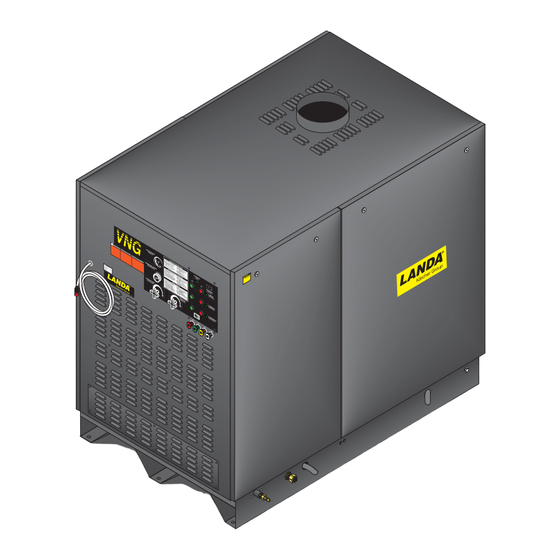
VNG/VLP
Hot Water - Electric Powered - Natural Gas or
LP Heated
Operator's Manual
Pressure Washer
MODELS:
VNG6-30024B
VNG4-20024A
1.109-575.0
1.109-563.0
VNG6-30024C
VNG4-20024B
1.109-576.0
1.109-564.0
VNG8-30024B
VNG4-20024C
1.109-579.0
1.109-565.0
VNG8-30024C
VNG4-20024H
1.109-580.0
1.109-568.0
VNG8-30024H
VNG4-30024A
1.109-582.0
1.109-569.0
VNG10-20024B
VNG4-30024B
1.109-559.0
1.109-570.0
VNG10-20024C
VNG4-30024C
1.109-560.0
1.109-571.0
VNG4-30024H
1.109-574.0
For the Landa Dealer nearest
you, consult our web page at
www.landa.com
8.913-939.0-AB
®
08/22/17
Advertisement
Table of Contents
Troubleshooting

Related Manuals for Kärcher Landa VLP Series


Summary of Contents for Kärcher Landa VLP Series
- Page 1 VNG/VLP ® Hot Water - Electric Powered - Natural Gas or LP Heated Operator’s Manual Pressure Washer MODELS: VNG6-30024B VNG4-20024A 1.109-575.0 1.109-563.0 VNG6-30024C VNG4-20024B 1.109-576.0 1.109-564.0 VNG8-30024B VNG4-20024C 1.109-579.0 1.109-565.0 VNG8-30024C VNG4-20024H 1.109-580.0 1.109-568.0 VNG8-30024H VNG4-30024A 1.109-582.0 1.109-569.0 VNG10-20024B VNG4-30024B 1.109-559.0 1.109-570.0 VNG10-20024C...
-
Page 2: Machine Data Label
Machine Data Label Landa VNG Operator’s Manual 8.913-939.0 - AB... -
Page 3: Table Of Contents
Table of Contents Machine Data Label ......2 Factory Set Parameters .....26 Maintenance Schedule . -
Page 4: How To Use This Manual
How To Use This Manual This manual contains the following sections: The SAFETY section contains important information regarding hazardous or unsafe practices of the • How to Use This Manual machine. Levels of hazards are identified that could • Safety result in product damage, personal injury, or severe •... -
Page 5: Safety
Safety Introduction & Safety Information Thank you for purchasing this Pressure Washer. We reserve the right to make changes at any time without incurring any obligation. Owner/User Responsibility: The owner and/or user must have an understanding of the manufacturer’s operating instructions and warnings before using this pressure washer. -
Page 6: Important Safety Information
Safety Important Safety Information WARNING: Flammable liquids can WARNING create fumes which can ignite, WARNING: If you do not follow these instructions causing property damage or exactly, a fire or explosion may result, causing severe injury. property damage, personal injury or loss of life. WARNING: Risk of explosion —... - Page 7 Safety 10. To reduce the risk of injury, close supervision is WARNING: Be extremely careful necessary when a machine is used near children. when using a ladder, scaffolding WARNING Do not allow children to operate the pressure or any other relatively unstable location.
-
Page 8: Propane Tank Safety Instructions
Safety 26. Exhaust gases should not be vented into a wall, a which seats securely against a female seat in the ceiling or a concealed space of a building. A draft POL valve – no pipe dope is necessary. Acme/ diverter must be installed to prevent down draft and Type 1 valves have right handed threads which are to allow cooling of exhaust temperatures. -
Page 9: Operations
Operations Component Identification Adjustable Thermostat Draft Diverter Variable Pressure Control Handle Pressure High Pressure Gauge Pump Nozzle & Coupler Stop Switch Spray Gun Side Panel Switch Hour Meter Trigger Burner Switch Detergent Voltage Incoming Valve Light Power Electrical Box Pump Light Water Supply Inlet... -
Page 10: Installation
Operations Installation Electrical Place machine in a convenient location providing The machine, when installed, must be electrically ample support, drainage and room for maintenance. grounded in accordance to local codes. Check for proper power supply using a volt meter; check the Location serial plate for the correct requirements. - Page 11 Operations VNG4-2000, 4-3000, 4-4000 Water In 3/4” GHF 45.00" 5.25" 3.50" 18.25" Electric 3.25" High Pressure Out Exhaust Gases 3/8" HP Nipple 10” Dia. 32.25" 14.50" 36.00" 10.00” Dia. 19.50” Dia. 36.00" Mininum Control Panel Gas In 1" NPT-M 47.50" Elect.
-
Page 12: Pipe Sizing Chart For Natural Gas
Operations Pipe Sizing Chart for Natural Gas ported, installed and used in the proper position. Do not transport, install or use a vertical cylinder in a horizontal The following chart is based on gas pressure in the or upside down position. Proper care must be taken to range 0-0.5 psi, specific gravity of 0.6 and pressure position a horizontal container in the correct position for loss of 0.5"... -
Page 13: Combustion And Ventilation Air
Operations Combustion and Ventilation Air Sampling Port and Rain Cap. An adapter can be installed between the collar and stack to adjust the Properly sized vents are vital for the safe and efficient diameter from 10” to 8” or 12” to 10”. operation of a pressure washer installed in a confined space. -
Page 14: Water Source
Operations Sampling Port A port for sampling flue gases and Before turning gas under pressure into piping, all measuring the flue gas temperature should be placed openings from which gas can escape should be closed. 18” above the flue collar. The port should be covered Immediately after turning on gas, the system should be when sampling is not being performed. -
Page 15: Start Up
Operations Start Up For Your Safety Read Before Lighting WARNING: Read and follow WARNING WARNING instructions carefully when installing or servicing machine. If you do not follow these instructions exactly, a fire or Failure to do so may result in explosion may result, causing property damage, personal injury or loss of life. - Page 16 Operations Check List Before Starting CAUTION! If “NO” has been checked on any of the following sixteen questions, do not operate this machine. Has gas supply been inspected by an authorized contractor to meet local codes? Is machine protected from downdraft and excessive wind? Is machine shielded from moisture or water spray?
-
Page 17: Assembly Instructions
Operations Assembly Instructions Safety Pump Switch Discharge Fitting Cold Water Source High High Pressure Spray Garden Pressure Hose Hose Hose STEP 3: Connect garden hose to STEP 2: Connect the high pressure STEP 1: Attach the high pressure the cold water source. hose to the discharge fitting. -
Page 18: Operating Instructions
Operations Operating Instructions Pump Switch Burner Switch STEP 1: Have an electrician STEP 2: Turn on main gas supply STEP 3: Push pump ‘ON’ switch, or connect power supply into elec- and depress and turn control knob turn to pump position and pull the trical box according to information to the ‘ON’... -
Page 19: Applying Detergent & General Operating Techniques
Operations Applying Detergent & Thermal Pump Protection General Operating Techniques If you run the engine for 3-5 minutes without pressing the trigger on the spray gun, circulating water in the WARNING: Some detergents may WARNING pump can reach high temperatures. When the water be harmful if inhaled or ingested, reaches this temperature, the pump protector engages causing severe nausea, fainting or... -
Page 20: Shutting Down And Clean Up
Operations Shutting Down And Clean Up veil OPER DAÑO Conn ecte à la terre procé disjon cteu ion, coule r l’eau z l’inter rupte . La USAR ONAL mise à l’aide cteur . Le à haute press faites . Mette “ON”... -
Page 21: Spray Nozzles
Operations Preventative Maintenance Call your Local Dealer for Assistance. Tampering with the factory setting may cause personal injury and 1. Check to see that water pump is properly or property damage, and will void the manufacturer's lubricated. warranty. 2. Follow Winterizing Procedures to prevent freeze damage to the pump and coils. -
Page 22: Maintenance
Maintenance Heating Coil 3. With a small screwdriver, rotate the adjustment screw clockwise to increase or counterclockwise to Condensation from Heating Coil decrease gas pressure. When cold water is being pumped into the water heater 4. Replace regulator adjustment screw cap. coil, and the burner is on, condensation will form on the coil and drip down into the burner compartment, giving the appearance of a leaking coil, particularly on cold... -
Page 23: Propane Gas
Maintenance Propane Gas Burner Features Operated Automatic Valve General Safety Precautions This machine is equipped with an Intermittent Pilot Have a qualified gas service person assist in any gas Ignition System. This system is designed to eliminate burner installation or service. Few maintenance people the need for a constant burning pilot. -
Page 24: Smart Relay Instructions
Maintenance Smart Relay Instructions NOTE: When setting time on clock, use only military time. Digital Timer (Optional) The cursor is now positioned on the weekday and The following are instructions on how to set the param- shows the following on the display window (see figure eters on the digital timer in Programming Mode. - Page 25 Maintenance Timer 3: 'Reset Delay Timer' NOTE: Ta is the accumulator timer and T is the adjustable timer (the variable that changes) Timer 3 controls how long the pump must run before resetting the ‘Lockout Timer’ (Timer 1). This allows the 5.
-
Page 26: Factory Set Parameters
Maintenance Factory Set Parameters (Auto Start/Stop with Lockout) TIMER VALUE DESCRIPTION Turns machine off after 4 hours of non-use. To restart push the Timer 1 04:00 Hours ‘Pump On’ switch. Pump will run in bypass for 30 seconds before shutting off, Timer 2 30:00 Seconds machine is still in standby mode. -
Page 27: Maintenance Schedule
Maintenance Preventative Maintenance This pressure washer was produced with the best available materials and quality craftsmanship. However, you as the owner have certain responsibilities for the correct care of the equipment. Attention to regular preventative main- tenance procedures will assist in preserving the performance of your equipment. Contact your Landa dealer for maintenance. -
Page 28: Troubleshooting - Burner
Maintenance Troubleshooting - Burner PROBLEM POSSIBLE CAUSE SOLUTION With power switch on, open trigger on spray gun A. No main power and set your test meter to the 24 volt scale. Probe terminals 24V and 24V(GND). If you do not read 24 FLOW &... - Page 29 Maintenance PROBLEM POSSIBLE CAUSE SOLUTION Faulty main valve coil in the Set test meter to 24 volt scale. gas valve With pilot flame on ignitor/sensor, probe terminals MV and MV/PV on the ignition control unit. If you Faulty ignitor/sensor and/or read 24 volts here, but not at the gas valve, there its wiring is a loose wiring connection.
-
Page 30: Troubleshooting
Maintenance Troubleshooting PROBLEM POSSIBLE CAUSE SOLUTION Faulty pressure gauge Install new gauge. Use larger garden hose; clean filter Insufficient water supply washer at water inlet. Match nozzle number to machine and/or replace Old, worn or incorrect spray nozzle with new nozzle. Belt slippage Tighten or replace;... - Page 31 Maintenance PROBLEM POSSIBLE CAUSE SOLUTION Incoming water to machine Lower incoming water temperature. warm or hot Gas pressure too high Call local gas company. WATER Detergent line sucking air Tighten all clamps. Check detergent lines for holes. TEMPERATURE TOO Defective high limit switch Replace.
- Page 32 Maintenance PROBLEM POSSIBLE CAUSE SOLUTION Valves worn Check and replace if necessary. Blockage in valve Check and replace if necessary. FLUCTUATING Check water supply and air seepage at joints in PRESSURE Pump sucking air suction line. Worn piston packing Check and replace if necessary. Check water supply and connections on Air in suction line suction line.
- Page 33 Maintenance PROBLEM POSSIBLE CAUSE SOLUTION Oil seal worn Check and replace if necessary. PRESENCE OF WATER IN OIL High humidity in air Check and change oil twice as often. WATER DRIPPING Piston packing worn Check and replace if necessary. FROM UNDER O-ring plunger retainer worn Check and replace if necessary.
- Page 34 Notes Landa VNG Operator’s Manual 8.913-939.0 - AB...
-
Page 35: Parts
Parts Parts LANDA VNG/VLP VNG4-20024A VNG6-30024B 1.109-563.0 1.109-575.0 VNG4-20024B VNG6-30024C 1.109-564.0 1.109-576.0 VNG4-20024C VNG8-30024B 1.109-565.0 1.109-579.0 VNG4-20024H VNG8-30024C 1.109-568.0 1.109-580.0 VNG4-30024A VNG8-30024H 1.109-569.0 1.109-582.0 VNG4-30024B VNG10-20024B 1.109-570.0 1.109-559.0 VNG4-30024C VNG10-20024C 1.109-571.0 1.109-560.0 VNG4-30024H 1.109-574.0 Landa VNG Operator’s Manual 8.913-939.0 - AB... -
Page 36: Landa - 4-2000, 4-3000
Landa - 4-2000, 4-3000 34, 98 78 - For Pump Detail See To Steam Page 42 Valve Detail See Electrical Box Illus. To Detergent Valve Detail See Electrical Box Illus. Landa VNG Operator’s Manual 8.913-939.0 - AB... - Page 37 Landa - 4-2000, 4-3000 Remote Control 40 41 22, 26, 27 89139390-3 Ignitor Assy. w/Cable Landa VNG Operator’s Manual 8.913-939.0 - AB...
- Page 38 Landa - 4-2000, 4-3000 PART NO. DESCRIPTION NOTES 8.912-539.0 PANEL, SIDE VNG-S 8.719-066.0 LATCH, VISE ACTION 9.802-072.0 26.5 ft TRIM, W/SPONGE 8.912-536.0 PANEL, TOP VNG-S 9.802-793.0 NUT, CAGE, 1/4” X 16 GAUGE 8.912-528.0 L-BRACKET, VNG 9.802-700.0 BOLT, 1/4” X 3/4” NC HH 9.802-802.0 WASHER, 1/4”...
- Page 39 Landa - 4-2000, 4-3000 PART NO. DESCRIPTION NOTES 8.725-395.0 NUT, 3/8” ESNA 8.725-394.0 WASHER, 3/8” FLAT, SAE 8.706-248.0 PLUG, 3/8”, COUNTER SUNK 9.149-003.0 DISCHARGE MANIFOLD 8.750-095.0 THERMOSTAT, 302° 8.750-096.0 KNOB 9.803-135.0 COIL, DURA 20" DIA, SCH 80 9.802-043.0 ELBOW, 1/2”, 90°, FEMALE, JIC 9.802-159.0 CONNECTOR, 1/4”...
- Page 40 Landa - 4-2000, 4-3000 PART NO. DESCRIPTION NOTES 8.707-000.0 CONNECTOR, 1/2” ANCHOR 9.802-260.0 4 ft. HOSE 5/8” 9.802-735.0 BOLT, 3/8” X 5-1/2” NC HH TAP 9.803-130.0 PLATFORM, MOTOR 3/16” 9.803-131.0 RAIL, PUMP, GENERAL COMBO 9.802-720.0 BOLT, 3/8” X 1” NC HH 9.803-532.0 ISOLATOR, 5/16”...
- Page 41 Landa - 4-2000, 4-3000 PART NO. DESCRIPTION NOTES 9.802-776.0 NUT, 5/16” ESNA 9.804-057.0 WASHER 8.706-294.0 BUSHING, 1/2” X 3/8” STEEL 8.706-109.0 NIPPLE, 3/4” X 7", BLACK PIPE 4.25 (4-3A, G) 9.802-425.0 CORD, SERVICE, SO, 8/3 COLEMAN NOT SHOWN 4.25 (4-2A, G) 9.802-436.0 CORD, SERVICE, SEO, 10/3,COLEMAN NOT SHOWN...
-
Page 42: Landa - 6-3000, 8-3000, 10-2000
Landa - 6-3000, 8-3000, 10-2000 31, 77 Detail See Control 11 - For Panel Float Tank Illus. Detail See Detail See Page 48 Electrical Box Illus. Landa VNG Operator’s Manual 8.913-939.0 - AB... - Page 43 Landa - 6-3000, 8-3000, 10-2000 Models 8-3000, 10-2000 Pump Assy. For Detail See Pump Exploded View 6-3000 Pump Assy. For Detail 39 38 See Pump Exploded View Opt. Remote Control Detail See Burner Illus. Landa VNG Operator’s Manual 8.913-939.0 - AB...
- Page 44 Landa - 6-3000, 8-3000, 10-2000 PART NO. DESCRIPTION NOTES 8.912-517.0 PANEL, SIDE, SMALL, VNG-L 8.912-515.0 PANEL, SIDE, LARGE, VNG-L 9.802-072.0 55 ft. TRIM, 1/16", W/SPONGE 8.719-066.0 LATCH, VISE ACTION 8.912-510.0 PANEL, TOP, VNG-L 9.802-793.0 NUT, CAGE, 1/4" X 16 GAUGE 8.912-528.0 L-BRACKET, VNG 8.912-527.0...
- Page 45 Landa - 6-3000, 8-3000, 10-2000 PART NO. DESCRIPTION NOTES 8.900-802.0 LABEL, LANDA LOGO 9.800-031.0 LABEL, PILOT WARNING LIGHT 8.719-515.0 BOLT, 3/8" X 1-1/4" NC, BLACK 8.912-249.0 CROSSHANGER, 1", SCH 80 9.802-024.0 ELBOW, 3/8" MPT x 1/2" FPT STREET, STEEL 8.912-381.0 RETAINER, PUMP TAKE-UP 8.912-512.0 PANEL, PULLY ACCESS...
- Page 46 Landa - 6-3000, 8-3000, 10-2000 PART NO. DESCRIPTION NOTES 8.912-521.0 BRACE, LEFT SIDE, VNG-L 9.196-012.0 SCREW, 10-24 X 1/4" 9.803-131.0 RAIL, PUMP (6-3) 8.912-533.0 POWER PLATFORM, VNG-L 9.802-067.0 BUMPER PAD, ENGINE 9.802-759.0 SCREW, 10/32" X 1/2" 8.707-381.0 RUPTURE DISC ASSY, 8500# 8.706-294.0 BUSHING, 1/2"...
- Page 47 Landa - 6-3000, 8-3000, 10-2000 PART NO. DESCRIPTION NOTES 9.802-720.0 BOLT, 3/8” X 1", NC HH 9.802-767.0 SCREW, 3/8" X 3/4", 12 GAUGE 9.802-718.0 U-BOLT, 5/16" X 1" PIPE 8.25 (6-3C;8-3C,10-2C) 9.802-437.0 CORD, SERVICE, SO, 10/4 NOT SHOWN 8.25 (8-3B, H; 10-2B) 9.803-992.0 CORD, SERVICE, SO, 4/4 NOT SHOWN...
-
Page 48: Control Panel
Control Panel Detergent Remote Detergent Inlet Operating System Line 36 - Detergent Line to Pump Steam Inlet Line Pump Steam Line Pump Landa VNG Operator’s Manual 8.913-939.0 - AB... - Page 49 Control Panel PART NO. DESCRIPTION NOTES 8.750-094.0 THERMOSTAT, 302° 8.706-162.0 ELBOW, 1/4” FEMALE PIPE 8.918-419.0 HOSE, 1/4” X 36", 2 WIRE GA. 9.802-810.0 WASHER, 5/8” FLAT 9.802-210.0 CLAMP, HOSE, UNI .46 - .54 8.706-958.0 HOSE BARB, 1/4” BARB, 90° 8.707-317.0 VALVE, CONTROL METERING 8.751-916.0 SWITCH GREEN, PUSH BUTTON...
- Page 50 Control Panel PART NO. DESCRIPTION NOTES 8.712-358.0 NOZZLE, 15055 YELLOW (4-2) 8.712-350.0 NOZZLE, 1504.5 YELLOW (4-3) 8.712-370.0 NOZZLE, 1502 YELLOW 8.712-379.0 NOZZLE, 1509 YELLOW (8-3) 8.712-387.0 NOZZLE, 1515 YELLOW (10-2) 8.712-359.0 NOZZLE, 2505.5 GREEN (4-2) 8.712-351.0 NOZZLE, 2504.5 GREEN (4-3) 8.712-371.0 NOZZLE, 2507 GREEN (6-3)
- Page 51 Control Panel PART NO. DESCRIPTION NOTES 8.712-150.0 GAUGE, 0-5000 PSI 8.751-915.0 SWITCH, RED, PUSH BUTTON 8.924-843.0 LABEL, VNG CONTROL PANEL, SR 9.802-254.0 36" HOSE, 1/4”, PUSH-ON (SMALL) 40" HOSE, 1/4”, PUSH-ON (LARGE) 8.719-011.0 WASHER, 5/8” STAR 9.802-064.0 GROMMET, RUBBER, NOZZLE 9.802-187.0 VALVE, METERING STEAM 8.918-180.0...
-
Page 52: Electrical Box Vng
Electrical Box VNG Landa VNG Operator’s Manual 8.913-939.0 - AB... - Page 53 Electrical Box VNG PART NO. DESCRIPTION NOTES 9.802-759.0 SCREW, 10/32” X 1/2” BHSOC 8.924-858.0 PANEL, ELECTRICAL BOX, SIDE 8.755-622.0 RELAY, SMART, 24V, 8I/4O 9.802-695.0 NUT 10/32 KEPS SEE SPECIFICATIONS CONTACTOR PAGES SEE SPECIFICATIONS OVERLOAD RELAY PAGES 8.924-857.0 BOX, ELECTRICAL VNG 9.804-003.0 SCREW, 1/4”...
- Page 54 Electrical Box VNG PART NO. DESCRIPTION NOTES 9.802-457.0 10" DIN RAIL 9.802-518.0 STRAIN RELIEF, 3/4” 9.802-793.0 NUT, CAGE, 1/4” X 16 GAUGE 9.802-515.0 STRAIN RELIEF, 1/2” 9.802-525.0 LOCKNUT, 1/2” 9.802-764.0 SCREW, 10/32” X 3/4” HEX 9.803-280.0 LOCKNUT, 1" 9.804-595.0 END BRACKET 8.753-064.0 TERMINAL BLOCK 6.643-249.0...
- Page 55 Electrical Box VNG PART NO. DESCRIPTION NOTES 9.802-784.0 NUT, 6-32 KEPS 8.718-733.0 SCREW, 6-32" X 5/8" 8.716-449.0 COVER, FUSE PROTECTOR 8.749-977.0 BAR, JUMPER NOT SHOWN 8.753-252.0 TERMINAL BLOCK, END CAP NOT SHOWN 8.716-216.0 HOLDER, FUSE NOT SHOWN 8.716-170.0 FUSE, MDL-1/2 250V NOT SHOWN 8.921-218.0 Q BAR, PLC...
-
Page 56: Burner - Vng 6-3000, 8-3000, 10-2000
Burner - VNG 6-3000, 8-3000, 10-2000 Landa VNG Operator’s Manual 8.913-939.0 - AB... - Page 57 Burner - VNG 6-3000, 8-3000, 10-2000 PART NO. DESCRIPTION NOTES 8.912-553.0 MODULE, WRAP, OUTER, LARGE COIL 8.751-384.0 BURNER RING X-96 NOZZLES W/# 54 NG 8.749-969.0 BURNER RING X-88 NOZZLES W/# 63 (LP OPTION) 8.912-550.0 DOOR, BURNER, LARGE 9.802-026.0 ELBOW, 1", BLACK PIPE, 90° 8.706-777.0 NIPPLE, 1/4"...
-
Page 58: Pump - Vng 4-2000, 4-3000, 6-3000
Pump - VNG 4-2000, 4-3000, 6-3000 4-2000 & 4-3000 6-3000 From Float Tank Landa VNG Operator’s Manual 8.913-939.0 - AB... - Page 59 Pump - VNG 4-2000, 4-3000, 6-3000 PART NO. DESCRIPTION NOTES SEE SPECIFICATIONS PUMP PAGES 9.803-131.0 RAIL, PUMP NOT SHOWN 8.933-006.0 SWITCH, FLOW MV60, YELLOW 9.802-362.0 UNLOADER, PA 8 GPM@3650, W/SWITCH 9.802-127.0 NIPPLE, 1/2” JIC X 3/8” PIPE 8.706-168.0 ELBOW, 3/8”, MALE PIPE 9.802-048.0 SWIVEL, 1/2”...
-
Page 60: Pump - Vng 8-3000, 10-2000
Pump - VNG 8-3000, 10-2000 Float Tank Float Tank Pressure Gauge Landa VNG Operator’s Manual 8.913-939.0 - AB... - Page 61 Pump - VNG 8-3000, 10-2000 PART NO. DESCRIPTION NOTES 8.920-590.0 PUMP, LANDA LX9536/L (8-3) 8.920-592.0 PUMP, LANDA LX1036/L (10-2) 8.912-215.0 RAIL, PUMP COMBO NOT SHOWN 9.803-557.0 ELBOW, 3/4” SAE X 3/4”, 90°, BRASS 8.706-852.0 CROSS, 3/4” FEMALE PIPE 8.706-923.0 BUSHING, 3/4” X 1/4” PIPE 8.706-854.0 TEE, 1/4”...
-
Page 62: Float Tank - Vngs
Float Tank - VNGS PART NO. DESCRIPTION NOTES 8.924-756.0 TANK, FLOAT SS 8.754-586.0 VALVE, FLOAT, W/ADAPTER 8.754-789.0 NUT, 1-8, HEX, GRADE A ZINC 8.750-743.0 BULKHEAD, 1/2” POLYPRO 8.706-441.0 ADAPTER, 1.5" SLIP X MT, PVC 80 8.706-485.0 BULKHEAD, 1 1/2', CYC, P/N-SP 1023 8.706-404.0 BUSHING, 1 1/2' X 1' MT X FT, PVC 80 8.706-424.0... -
Page 63: Float Tank - Vngl
Float Tank - VNGL PART NO. DESCRIPTION NOTES 8.912-518.0 ASSEMBLY, FLOAT TANK, S.S. 8.749-329.0 VALVE, FLOAT, 3/4” 8.707-025.0 STEM, 10" FLOAT 8.706-512.0 BALL, FLOAT, BLACK PLASTIC 3.25 9.802-071.0 TRIM, 750 B2 X 1/16” BLACK 9.802-050.0 ADAPTER, 3/4” X 3/4” MT X INSERT 90° 8.706-800.0 NIPPLE, 3/4”... -
Page 64: Hose & Spray Gun
Hose & Spray Gun Pressure Nozzle Landa VNG Operator’s Manual 8.913-939.0 - AB... - Page 65 Hose & Spray Gun PART NO. DESCRIPTION NOTES 9.802-165.0 COUPLER, 1/4”, MALE 9.802-096.0 O-RING, SMALL COUPLER, HIGH HEAT, 1/4" NOT SHOWN 8.711-308.0 WAND, SS, V.P. WAND, AR W/COUPLER (AL 344) 8.710-722.0 WAND ONLY, SS.V.P. WAND, AR (AL 344) AL83455VPKIT REPAIR KIT, AR SS SEAT (AL 334, 344) 9.802-286.0 NOZZLE ONLY, 1/8”...
-
Page 66: Specifications
Specifications Parts Specification: Landa Pump Machine Pump Pulley Part # Pulley Bushing Bushing Part # Model Model Part # 4-20024A LT6036 8.921-712.0 2AK84H 9.802-375.0 25mm 9.802-403.0 4-20024B LT6036 8.921-712.0 2AK84H 9.802-375.0 25mm 9.802-403.0 4-20024C LT6036 8.921-712.0 2AK84H 9.802-375.0 25mm 9.802-403.0 4-20024H LT6036 8.921-712.0... - Page 67 Specifications Machine Motor Pulley Size Voltage/PH Pulley Bushing Model Con’t Part # Part # 4-20024A 6 HP 230V/1PH 9.802-336.0 2AK46H 8.715-547.0 1-1/8” 4-20024B 6 HP 230V/3PH 8.751-004.0 2AK46H 8.715-547.0 1-1/8” 4-20024C 6 HP 460V/3PH 8.751-004.0 2AK46H 8.715-547.0 1-1/8” 4-20024H 6 HP 208V/3PH 8.756-426.0 2AK46H...
- Page 68 Specifications Parts Specification: Landa Pump (Con’t) Machine Bushing Belt Belt Motor Motor Stepdown Model Con’t Part # Size/Qty Part # Contact Overload Transformer 4-20024A 9.802-400.0 AX37 (2) 9.802-409.0 8.724-280.0 9.803-662. 0 4-20024B 9.802-400.0 AX37 (2) 9.802-409.0 8.724-275.0 8.724-304.0 9.803-662.0 4-20024C 9.802-400.0 AX37 (2) 9.802-409.0...
- Page 69 Specifications Machine Primary Primary Secondary Secondary Stepdown Model Con’t Fuse Fuse Part # Fuse Fuse Part # Transformer 4-20024A 8.713-286.0 (2) 6.25A 8.716-199.0 9.802-553.0 4-20024B 8.713-286.0 (2) 6.25A 8.716-199.0 9.802-553.0 4-20024C 8.713-080.0 (2) 6.25A 8.716-199.0 9.802-553.0 4-20024H 8.713-286.0 (2) 6.25A 8.716-199.0 9.802-553.0 4-30024A...
-
Page 70: Burner Specifications
Burner Specifications BURNER PILOT ORIFICE MODEL JET SIZE GAS VALVE ASSEMBLY CONVERSION VNG4-2000 X-44 3/4" VB8304 VNG4-3000 X-44 3/4" VB8304 VNG6-3000 SQ-98 1" V8943B VNG8-3000 SQ-98 1" V8943B VNG10-2000 SQ-98 1" V8943B VLP4-2000 X-44 3/4" V8943B-393691 LP Kit VLP4-3000 X-44 3/4"... -
Page 71: Burner Basic Facts
Burner Basic Facts BASED ON 60° F PROPANE BUTANE Formula C3H8 C4H10 Vaporization Point (°F) -43.7 31.1 Specific Gravity (Vapor) 1.522 2.006 Specific Gravity (Liquid) 0.508 0.584 Lbs. Per Gallon (Liquid) 4.23 4.87 B.T.U. Per Cubic Foot (Vapor) 2.563 3.39 B.T.U. -
Page 72: Unloader - Mg4000 W/ Microswitch
Unloader - MG4000 w/ Microswitch Item 9 Exploded View PART NO. DESCRIPTION NOTES 39.0023 39.0116 KNOB 38.0044 NUT FOR KNOB 35.0006 SPRING RETAINER DISK 38.0007 HIGH PRESSURE SPRING 100 BAR Landa VNG Operator’s Manual 8.913-939.0 - AB... - Page 73 Unloader - MG4000 w/ Microswitch PART NO. DESCRIPTION NOTES 38.0006 HIGH PRESSURE SPRING 200 BAR 38.0005 HIGH PRESSURE SPRING 275 BAR 38.0004 HIGH PRESSURE SPRING 310 BAR 38.0128 35.0186 39.0014 YELLOW O-RING 39.0015 RED O-RING 39.0013 BLUE O-RING 39.0012 BLACK O-RING 18.0291 STEM 35.0187...
- Page 74 Unloader - MG4000 w/ Microswitch PART NO. DESCRIPTION NOTES 39.0097* MEMBRANE SEAL 41.012 ELECTRIC PART 38.0123 FORK 35.0184* NO-RETURN PISTON WITH 0-RING 35.0005 INJECTOR NIPPLE 35.0004 1/4” NUT 35.0146 INJECTOR BODY 36.0161 SPRING 36.0182 BALL 39.0166 O-RING, 5.28X1.78 MM HOSE BARB NIPPLE (FOR ADJUSTABLE 35.0158 INJECTOR) 39.014...
- Page 75 Unloader - MG4000 w/ Microswitch ITEM 9 PARTS LIST PART NO. DESCRIPTION NOTES 36.0118 STEM 35.0185 NIPPLE 39.0164* O-RING 15.54X2.62 MM 39.0066* BACK-UP RING 39.0161* O-RING 7.6X2.62 MM 39.0132 O-RING 4.48X1.78 MM 35.0214 RETAINING FERRULE 39.0068* BACK-UP RING 39.0163* O-RING 10.78X2.62 MM 39.0065* BACK-UP RING 36.0004...
-
Page 76: Vb8 Valve
VB8 Valve VB8 Valve, 9.802-362.0 (5-3027) PART NO. DESCRIPTION NOTES 60.0058.31 DELIVERY COUPL., 3/8F BSP BRASS 10.3070.02 O-RING 1.78 X 18.77 MM NI 85 60.0053.51 SPRING, 0.7 X 9 X 20 MM SST. 60.0052.31 SHUTTER PIN, BRASS 10.3070.02 O-RING, 3 X 6 MM 60.1201.35 HOUSING-BB8, 3/8 M BSP C/SUNK, BRASS 10.3170.08... - Page 77 VB8 Valve PART NO. DESCRIPTION NOTES 14.3719.00 WASHER, 9 X 15 X 1, 5 MM SST. 60.1208.61 SPRING, 3.2 X15.4 X 33 MM Z.PL. 60.1210.31 SPRING GUIDING RING 14.7421.50 BALL, 1/4" SST. 60.1209.31 VALVE REGULATING INSERT, BRASS 29.0087.51 U-BOLT, SST. 29.0089.84 HOUSING, PR5 PA BLACK 12.5006.00...
-
Page 78: Pump - Lt.2 Series
Pump - LT.2 Series TORQUE SPECS ITEM # FT. LBS. PART NO. DESCRIPTION NOTES 8.752-825.0 CRANKCASE PLUNGER OIL SEAL SEE KITS TABLE O-RING Ø1.78 X 37.82 SEE KITS TABLE PRESSURE RING, 18MM SEE KITS TABLE U-SEAL, 18MM SEE KITS TABLE INTERMEDIATE RING, 18MM SEE KITS TABLE U-SEAL, 18MM... - Page 79 Pump - LT.2 Series PART NO. DESCRIPTION NOTES 8.707-262.0 BRASS PLUG 3/8 VALVE SEAT SEE KITS TABLE VALVE PLATE SEE KITS TABLE VALVE SPRING SEE KITS TABLE VALVE CAGE SEE KITS TABLE 8.752-830.0 HEX SCREW 9.802-884.0 WASHER 9.803-182.0 CLOSED BEARING HOUSING 9.803-186.0 O-RING Ø2.62 X 71.12 9.803-160.0...
-
Page 80: Pump - Lx.2 Series
Pump - LX.2 Series XLT3020S XLT3816S XLT1830 XLT2230 XLT2530 XLT2520 XLT2730 XLT3025 XLT3020 TORQUE SPECS XLT3325 XLT3517 ITEM # FT. LBS. XLT4017 XLT4014 XLT4317 XLT5015 XLT5415 HAWK Pompe XLT serie 2011 PART NO. DESCRIPTION NOTES 8.752-825.0 CRANKCASE PLUNGER OIL SEAL SEE KITS TABLE O-RING Ø1.78 X 37.82 SEE KITS TABLE... - Page 81 Pump - LX.2 Series PART NO. DESCRIPTION NOTES VALVE SEAT SEE KITS TABLE VALVE PLATE SEE KITS TABLE VALVE SPRING SEE KITS TABLE VALVE CAGE SEE KITS TABLE 8.752-830.0 HEX SCREW 9.802-884.0 WASHER 9.803-182.0 CLOSED BEARING HOUSING 9.803-186.0 O-RING Ø2.62 X 71.12 9.803-160.0 ROLLER BEARING 8.752-829.0...
- Page 82 ® 8.913-939.0 • Printed in U.S.A.
Need help?
Do you have a question about the Landa VLP Series and is the answer not in the manual?
Questions and answers