
Related Manuals for Heyer Modular+


Summary of Contents for Heyer Modular+
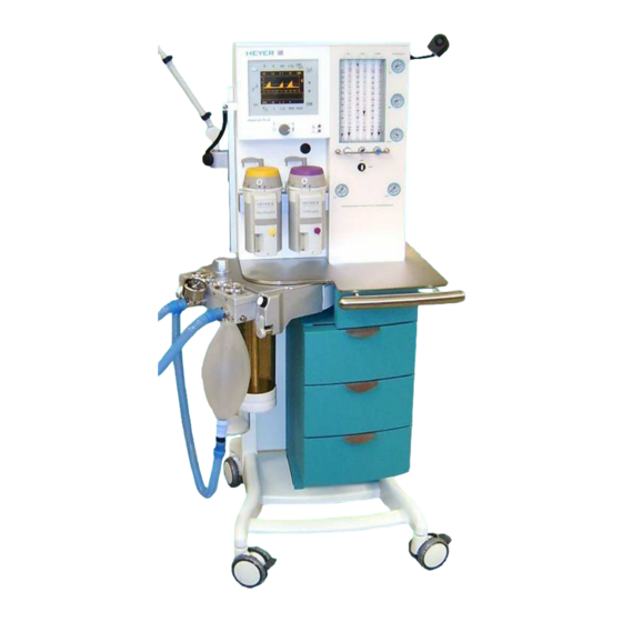
- Page 1 H E Y E R Modular + Anesthesia System Service Manual Rev.2.1.0 Software version Service software: 1.8...
- Page 2 Table of Contents HEYER MEDICAL AG Carl-Heyer-Strasse 1-3 56130 Bad Ems Germany Tel. +49 - 2603 – 791 - 3 Fax. +49 - 2603 – 791 - 209 E-mail: info@heyermedical.de...
-
Page 3: Table Of Contents
Theory of Operation 0 Table of Contents Table of Contents ..........................3 Table of Figures ........................6 General Information.......................... 7 Guidelines ..........................7 Product improvements ......................7 Manufacturer’s Liability ......................7 Manufacturer’s specification ..................... 8 Updating status ......................... 8 Warning, Precautions and Notes ....................9 1.6.1 Warnings.......................... - Page 4 Theory of Operation 2.15.4.4 Inspiratory and expiratory valves................38 2.15.4.5 Airway pressure relief valve ..................38 2.15.4.6 Room Air valve ......................38 2.15.4.7 Diaphragm valves....................38 2.15.2.7.1 Status of the diaphragm valves:............... 39 2.15.2.7.2 Machine OFF Or Ventilator In Standby ............39 2.15.2.7.3 Manual / Spontaneous Mode, INSPIRATION And EXPIRATION....
- Page 5 Theory of Operation 4.6.2.7 Characteristic of the Proportional Valve ..............94 4.6.2.8 External Flow Sensor Calibration ................96 Preventive Maintenance......................... 99 6 Month Service Interval ......................99 12 Month Service Interval ..................... 100 36 Month Service Interval ..................... 100 Cleaning ..........................101 5.4.1 Cleaning and disinfecting the apparatus ...............
-
Page 6: Table Of Figures
Theory of Operation 0.1 Table of Figures Fig. 1 Line Terminal Block, 120/230V AC Supply ................. 15 Fig. 2 Overview electrical components....................16 Fig. 3 Power supply module ......................... 17 Fig. 4 Module 1 PC board........................21 Fig. 5 View on module 2 ........................23 Fig. -
Page 7: General Information
HEYER reserves the right to improve their products or revise the instructions without prior notice. This manual deals with the status of the anesthesia system HEYER Modular + at the time of issue. HEYER is not obliged to retrofit former models subject to improvements and modifications. An exception to be examined will be made when improvements or modifications due to design and production deviations are influencing the patient’s safety or would entail malfunctioning of the... -
Page 8: Manufacturer's Specification
Theory of Operation 1.4 Manufacturer’s specification HEYER MODULAR + Product: Manufacturer: Heyer Medical AG Carl-Heyer-Strasse 1-3 56130 Bad Ems Germany Tel. + 49 2603 / 791-3 Fax. +49 2603 / 791-209 E-mail: info@heyermedical.de 1.5 Updating status State of this service manual: Rev. 2.1.0 of February 2004... -
Page 9: Warning, Precautions And Notes
Theory of Operation 1.6 Warning, Precautions and Notes Warnings alert the user to potential serious outcomes (death, injury or serious adverse events) to the patient or user. Precautions alert the reader to exercise special care necessary for the safe and effective use of the device Notes are a general information statement concerning the Modular + Please read adhere to all warning, precautions and notes listed here and in the appropriate areas... -
Page 10: Precautions
Theory of Operation 1.6.2 Precautions Caution: Refer to the maintenance intervals in the Preventive Maintenance section for guidance on which steps are preformed when. Caution: Use surgical gloves whenever touching or disassembling valves or other internal components of the Patient Module. Caution: If possible, always connect the output of the APL valve to the anesthetic removal line, usually installed in the operation theater. -
Page 11: Notes
1.6.3 Notes Note: Unauthorized servicing may void the remainder of the warranty. Check with the factory or with a local authorized HEYER dealer to determine the warranty status of a particular instrument. - Page 12 Theory of Operation This page intentionally left blank...
-
Page 13: Theory Of Operation
Repair Information 2 Theory of Operation The anesthesia system HEYER MODULAR + represents a flexible employable workstation to apply and monitor anesthesia inhalation in semi-closed and almost closed circuits in low flow techniques for minimized consumption of gas and anesthetics. -
Page 14: Fresh Gas Decoupling
Repair Information 2.5.1 P limiting on alarm violation Exceeding the P alarm limit automatically halts the inspiratory phase preventing airway pressure from exceeding the high alarm setting. In the CMV mode, the setting of the P peak pressure provides pressure limitation. When reaching this pressure limit, a warning (alarm) “Peak greater than ”... -
Page 15: Electrical Supply
Repair Information 2.8 Electrical supply The line cord of the Modular + is connected to an internal terminal block. Directly connected to this terminal are convenience receptacles and the unit itself. Line supply to the receptacles is available with the line cord connected. Line supply for the unit is switched by the main switch at the right side of the unit. -
Page 16: Electrical Components
Repair Information 2.8.1 Electrical components RS 232 RS 232 RS 232 interface interface interface Option 1 Option 2 module 1 Display Controller module 1 Communication flow meter backlight RS 232 module 1 interface Display transformer module 1 power supply Touch Screen main switch battery... -
Page 17: Power Supply Module
Repair Information 2.9 Power supply module The power supply module is located in the frame behind the drawers. This module serves for the voltage supply of the ventilator modules 1 and 2, the flow meter block illumination, the patient circuit heating blanket and the charging / discharging control for the battery. -
Page 18: Connectors On Power Supply Board Avm 2-1
Repair Information 2.9.1 Connectors on power supply board AVM 2-1 Connector connected to Pin. def. Func. / Signal Color / No. Module 1 X1-1 yellow X1-2 X1-3 green X1-4 +12V blue Connector connected to Pin. def. Func. / Signal Color / No. X2-1 X2-2 X2-3... -
Page 19: Fuses On Power Supply Board Avm 2-1
Repair Information Connector connected to Pin. def. Func. / Signal Color / No. int. connection X12-1 AC, N 110V/230V blue AC IN terminal X12-2 AC , L 110V/230V black Connector connected to Pin. def. Func. / Signal Color / No. Module 2 X13-1 +12V... -
Page 20: Charging / Discharging Control For The Battery
Repair Information 2.9.3 Charging / discharging control for the battery: The charging / discharging control for the battery is also located on the power supply board AVM 2-1. Status indicators as red, green and yellow LEDs are located on the board to show functions like check or charging of the battery. -
Page 21: Module 1
Repair Information 2.10 Module 1 Ventilator module 1 consists of two processor boards. This module serves for the operation of touch screen interface with different menus displayed on the display. All safety functions, e.g. the complete ventilator control, are located on ventilator module 2. Module 1 is connected to module 2 by means of an RS 232C- interface. -
Page 22: Connectors On Module 1
Repair Information 2.10.1 Connectors on module 1 Connector connected to Plug conf. Func. / Signal Module 2 10 pole communication with module 2 Connector connected to Plug conf. Func. / Signal EL Display 20 pole Connected to the display Connector connected to Plug conf. -
Page 23: Ventilator Module 2, Avm 3-1 And Avm 3-2
Repair Information 2.11 Ventilator Module 2, AVM 3-1 and AVM 3-2 Ventilator module 2 serves for the active ventilator control. Module 2 consists of two CPU boards, the CPU board AVM3-1 with µP1 serves for a continuous validation of control actions generated by CPU board AVM3-2 and for the communication between module 2 and module 1. -
Page 24: Parts List Module 2
Repair Information 2.11.1 Parts list module 2 Pos. No. Description Order No. Ventilator module 2, complete 460-1150 2.11.2 Connectors on module 2 2.11.2.1 Plug connectors on board AVM 3-1 Connector connected to Plug conf. Func. / Signal Module 1 28 pole communication with module 1 Connector... -
Page 25: Plug Connectors On Board Avm3-2
The battery is a maintenance free seal lead acid type. The recharging time is a maximum of 7 hours with a fully depleted battery. The backup time is about 30 minutes with a fully charged battery. To prevent unintended loss of battery operation, it is recommended to replace it with a new HEYER battery every 3 years. -
Page 26: Ventilator Pneumatic
Repair Information 2.14 Ventilator pneumatic Fig. 6 Ventilator pneumatic... -
Page 27: Ventilator Pneumatic Drive
Repair Information 2.14.1 Ventilator pneumatic drive Air or Oxygen, in the CMV mode, serves as driving gas for the ventilator. In addition to the flow meter block, a pressure reducer, reducing the supply pressure to 200 kPa (2 bar; 29 PSI), is supplied by the Air or oxygen connection. -
Page 28: Pneumatic Driving Module
Repair Information 2.14.5 Pneumatic driving module The driving module consists of the proportional valve and flow divider with an internal flow sensor. The proportional valve supplied by the HP pressure reducer generates a driving gas flow of 0-75 l/min in relation to the control voltage of the proportional valve of 0 - 5V DC . -
Page 29: The Patient Module (Circle System)
Repair Information 2.15 The patient module (circle system) 2.15.1 Top and back side view on the patient module Fig. 7 Top and backside view on the patient module Pos. Description 1. Expiratory valve (passive) 2. Airway pressure limiting valve (APL) 3. -
Page 30: Bottom And Back Side View On The Patient Module
Repair Information 2.15.2 Bottom and back side view on the patient module Fig. 8 Bottom and backside view on the patient module Pos. Description Fixing screws for locking bolt Exhaust for driving gas Driving gas in- and outlet to bellows dome Thread for CO absorber canister fixing, outlet from patient module to absorber Inlet for re-breathing gas from absorber to patient module... -
Page 31: Functional Representations Of The Patient Module
Repair Information 2.15.3 Functional representations of the patient module gas- monitoring Fig. 9 Survey of the patient module Pos. Description Patient's y-piece Side stream gas monitor Inspiratory bacterial filter Expiratory bacterial filter Airway pressure monitor connection Inspiratory valve (passive) Expiratory valve (passive) Spirometry sensor Airway pressure limiting valve (APL) Waste gas outlet... -
Page 32: Cmv Mode, Inspiration
Repair Information 2.15.3.1 CMV mode, inspiration gas monitoring decoupling valve expiratory valve when reservoir pressure bellows valve is > 2 mbar MV3 ="1" MV2 ="1" MV4 ="1" MV1 ="1" Fig. 10 Survey of the patient module, CMV mode, inspiration... -
Page 33: Cmv Mode, Expiration
Repair Information 2.15.3.2 CMV mode, expiration gas monitoring decoupling valve expiratory valve bellows valve when reservoir pressure is > 2 mbar MV3 ="0" MV2 ="0" MV4 ="0" MV1 ="0" Fig. 11 Survey of the patient module, CMV mode, expiration... -
Page 34: Manual Mode, Inspiration
Repair Information 2.15.3.3 Manual mode, inspiration gas monitoring decoupling valve expiratory valve when the set respiratory bellows valve pressure is attained MV3 ="0" MV2 ="0" MV4 ="0" MV1 ="0" Fig. 12 Survey of the patient module, Manual mode, inspiration... -
Page 35: Manual Mode, Expiration
Repair Information 2.15.3.4 Manual mode, expiration gas monitoring decoupling valve expiratory valve bellows valve MV3 ="0" MV2 ="0" MV4 ="0" MV1 ="0" Fig. 13 Survey of the patient module, Manual mode, expiration... -
Page 36: Spontaneous Mode, Inspiration
Repair Information 2.15.3.5 Spontaneous mode, inspiration gas monitoring decoupling valve emergency air valve opens at p < - 3 mbar expiratory valve when reservoir pressure bellows valve is > 2 mbar MV3 ="0" MV2 ="0" MV4 ="0" MV1 ="0" Fig. 14 Survey of the patient module, Spontaneous mode, inspiration... -
Page 37: Spontaneous Mode, Expiration
Repair Information 2.15.3.6 Spontaneous mode, expiration gas monitoring decoupling valve expiratory valve waste gas bellows valve MV3 ="0" MV2 ="0" MV4 ="0" MV1 ="0" Fig. 15 Survey of the patient module, Spontaneous mode, expiration... -
Page 38: Components Of The Patient Module
Repair Information 2.15.4 Components of the patient module 2.15.4.1 Ventilation bellows system The ventilator’s driving system can be characterized as a constant flow generator. The driving gas of this generator fills the bellows dome to compress the bellows. The breathing gas is pressed out of the bellows into the circuit. -
Page 39: Status Of The Diaphragm Valves
Repair Information 2.15.2.7.1 Status of the diaphragm/membrane valves: The diaphragm valves are pneumatically operated by solenoid valves. The following list shows the correspondence between diaphragm valve, solenoid valve and pressure port. Valve Bellows valve Exp. valve Decoupling valve controlled by MV 1 MV 2 MV 4... -
Page 40: Compliance Test Patient Module
Repair Information 2.15.2.7.7 Compliance Test Patient Module The compliance test patient module is divided in 3 phases. Phase 1. Flow into the re-breathing system and test of flow sensors. Valve MV 1 Activity Pressure on port 5, Yes 1, No 6, Yes no sup. -
Page 41: Repair Information
Maintenance and Calibration 3 Repair Information 3.1 Introduction This chapter of the service manual provides the necessary technical information to perform repairs to the instrument. The most important perquisites for effective troubleshooting are a trough understanding of the instruments functions, as well as understanding the principals of operation. 3.2 Warnings and precautions In the event the instrument covers are removed, observe the following warnings and guidelines 3.2.1 Precautions... -
Page 42: Troubleshooting Guidelines
Maintenance and Calibration 3.3 Troubleshooting Guidelines 1. Identify the problem – Due to the wide variety of potential symptoms, certain problems may be more subtle than others. Following the guidelines of the tests will help determine the problem if one exists. 2. - Page 43 Maintenance and Calibration Corrective action Display message Cause Corrective action User Service technician AVM3-2 CMV/ PCV Finish the case with manual Recalibrate proportional Valve Error: Use Manual ventilation; valve, internal flow sensor and Ventilation The actual internal flow value Take the machine out of use; characteristic Call Service should be 0 during expiration...
- Page 44 Maintenance and Calibration Corrective action Display message Cause Corrective action User Service technician EEPROM is checked during the Take the machine out of use; Recalibrate complete System Error start up and during the sensor Call Service system. If that does not solve Cal Required test for CRC errors problem...
- Page 45 Maintenance and Calibration Corrective action Display message Cause Corrective action User Service technician AVM3-1 Battery mode Restore the line supply 1. Charge the battery 10 min. remaining 10 minutes of battery use left 2. Check the capacity of the battery, if necessary, exchange AVM3-1 Battery mode Restore the line supply 1.
-
Page 46: Alarm Messages During The Compliance Test, Leak Test And O2 Calibration
Maintenance and Calibration 3.4.2 Alarm messages during the compliance test, leak test and O2 calibration Corrective action Display message Cause Corrective action User Service technician AVM 3-2 Repeat the compliance test Check the breathing circuit for System Resistance If with in 1 sec. after a flow of obstructions too high 12 l/min has been generated, a... -
Page 47: Messages During The System Tests
Maintenance and Calibration Corrective action Display message Cause Corrective action User Service technician AVM 3-2 Vent the system by opening the Relieve the system pressure, System pressurized A pressure larger than 10 mbar Breathing circuit. Monitor recalibrate pressure is measured before the start of sensors system pressure the compliance test... - Page 48 Maintenance and Calibration Result Compliance Test Compliance Test Leak Test O2 calibration Start Up O2Sensor calibration successful O2 too high O2 concentration too high Expose Sensor to room air Press Enter to Start O2 Sensor too old O2 Sensor is out of rage Replace O2 Sensor Press Enter to Start...
-
Page 49: Symptoms Of Fuse Failures
Maintenance and Calibration 3.4.3 Symptoms of Fuse Failures The following table shows the reaction to a failed fuse on the power supply board. The fuses F2, F3, F4, F5 and F6 have been removed from the power supply module and are therefore subject of the production date. -
Page 50: Required Tools
Maintenance and Calibration 3.5 Required Tools Item Part Description Specification Number Number Operation manual HEYER specification Service manual HEYER specification 900-4726 Calibration pump, Pressure sensors 0 – 80 cmH Safety analyzer For electrical tests according to IEC- 601-1,B Digital Volt Meter... -
Page 51: Removing The Patient Module
Maintenance and Calibration 3.6.3 Removing the Patient Module 1. Remove the CO absorber dome. 2. Remove the bag in bottle system. 3. Remove the O cell cable from the O cell. 4. Remove the scavenger hose. 5. Remove the breathing circuit. 6. -
Page 52: Inspecting/Replacing The Decoupling, Bellow And Expiratory Valves
Maintenance and Calibration 3.6.7 Inspecting/replacing the Decoupling, Bellow and Expiratory Valves 1. To replace the Patient modules rear side valves’ membrane, undo the coupling nut. 2. After removing the valve assembly, undo the black nut securing the valve. 3. Inspect and /or replace the valve, ensuring no hole or deformity that would cause a leak. 4. -
Page 53: Removing The Pressure Gauges
Maintenance and Calibration 3.6.11 Removing the pressure gauges 1. Remove the Gas Block Module 2. Remove the metal compression fittings from the gauge. 3. Remove the gauges from the front panel enclosure. 4. Reinstall in reverse order 5. Connect gas supplies at each gauge. Observe and test compression fittings for leaks. 3.6.12 Removing the Module 2 Circuit Board Set 1. -
Page 54: Removing Internal Regulators, Proportional Valve And Flow Divider
Maintenance and Calibration 3.6.15 Removing Internal Regulators, Proportional Valve and Flow Divider 1. Disconnect all sources of pressurized gas. 2. Remove vaporizers. 3. Remove the access panel attached to the yoke assembly. 4. Remove the screws holding the swinging rear access panel. 5. -
Page 55: Maintenance And Calibration
Possible fire hazard. Fuses (i.e., additional sockets) must only be replaced by fuses of the same type with the same rating. WARNING: Possible electrical shock hazard. The machine may only be opened by HEYER authorized service personnel. CAUTION: Refer to the maintenance intervals in the preventive maintenance section for guidance on which steps are preformed when. -
Page 56: Test Procedure
Preventive Maintenance CAUTION: The spring in the top of the APL valve may not be stressed. After removal, ensure that the APL valve is in position “CMV” and place to one side, taking care that the spring is not unduly loaded. CAUTION: Use cleaning agent sparingly. -
Page 57: Fig. 16 Patient Module, Front View
Preventive Maintenance valve inlet 40° turned drawn insp. port reservoir / exp. port bag port Fig. 16 Patient module, front view... -
Page 58: Fig. 17 Patient Module, Top View
Preventive Maintenance bellows control diaphragm valve expiratory decoupling diaphragm diaphragm valve valve Fig. 17 Patient module, top view (diaphragm version) Pos. No. Description Order No. Airway pressure relief valve, cpl. 323-0095 Emergency air valve, cpl. 323-0098 Inspiratory valve, cpl. 323-0096 Expiratory valve, cpl. -
Page 59: Fig. 18 Supply Inlet Filters And Water Traps
Preventive Maintenance Ensure that the O-ring (323-0147) and the packing ring (980-1170) of the CO absorber are intact. Ensure that the O-ring (323-0147) on the ventilator bellow is intact. Ensure that the O-ring (049-3182) on each vaporizer mount is intact. Check O-rings (049-3052) of the docking station ports (located between the patient module and its docking station). - Page 60 Preventive Maintenance 15 Reassemble the patient module and install back into the docking station. 16 Turn off the Modular + power switch. 17 Verify O O and AIR tank check valves. * Connect and open a full gas tank on each yoke Withdraw the gas connecting coupling from the supply outlet.
-
Page 61: Power Supply Checks
Preventive Maintenance 4.3.3 Power supply checks Remove the screws from the upper panel. Swing the door open exposing the power supply PC board. The power supply assembly is attached to the door. Carefully remove the plastic shield. Warning: AC voltage is present Adjust P1 on the power supply board for +5.2 VDC. -
Page 62: Functional Tests
Preventive Maintenance 4.3.4 Functional Tests 4.3.4.1 Pneumatic tests Perform automatic compliance test. Turn on the Modular + and ensure adequate drive gas is present Attach a breathing circuit the patient module. Seal the Y-piece by attaching the open port to the parking place on the side of the patient module. -
Page 63: Alarm Tests
Preventive Maintenance Verify APL Valve accuracy. Attach a breathing circuit the patient module. Connect the y-piece to the hose end where the reservoir bag normally is connected. Set a fresh gas flow of 5 l/min. Set the APL valve to each pressure graduation (10, 20, 30, 40 and 50 Pa x 100 (mbar; Compare the valves on the pressure gauge with the valve settings. -
Page 64: Fig. 21 O2 Whistle Adjustment (Appearance May Differ Due To Different Configuration Options)
Preventive Maintenance Verify O2 pressure loss alarm (whistle) and N2O cutoff. Ventilate a test lung in the CMV mode. Set the AIR/N O switch to N Flow 1 l/min O and 1 l/min N O using the flow meter spindle valves. supply to the Modular + . -
Page 65: Electrical Tests
Preventive Maintenance Verify N ratio system. Set the O and N O valves to minimum. Rotate the N O valve throughout its range from 0.5 to 10 l/min. Using the readings from the flow tube, verify that no less than 25% ± 5% O can be achieved at any N O flow rate. -
Page 66: Service Software
Preventive Maintenance 4.4 Service Software Calibration and testing is accomplished through software driven service diagnostics. The current software version is displayed in the main menu. To enter the service software Turn off the Mains switch. Set the Switch to standby. Turn on the mains switch. Select the keys OPT. -
Page 67: Key Code Access
Preventive Maintenance To Exit the Service Software To exit the service software, select the Exit (or Quit key in advanced screens) to return to the Initialization screen menu Shut down the Modular + after each diagnose software session by turning off the mains switch. 4.5 Key code Access Enter a key code (provided during service training) to invoke the service software. -
Page 68: Navigation
Preventive Maintenance 4.6 Navigation While in the main menu screen, select individual keys to calibrate the O sensor, Temperature sensor, P1 pressure sensor, P2 pressure sensor, Internal flow sensor, External flow sensor or proportional valve. Select the test menu screen. Fig. -
Page 69: Fig. 25 Test Menu Screen
Preventive Maintenance While in the test menu screen, Pressure, O2 and Temperature sensors, Proportional valve output, Solenoid valve continuity, Power indicators, and Heating blanket thermal cutoff. Fig. 25 Test menu screen Note: The motor button has no function with units without the patient module... -
Page 70: System Testing
Preventive Maintenance 4.6.1 System Testing Conduct Motor Control test. (Skip to step 1-f if already in the Test menu) Note: Skip to step 2 if you have a unit without the patient module motor Select the Select the keys. OPT. iii) Select KEYCODE to enter the diagnostic screens. -
Page 71: Fig. 27 Docking Station, Start/ Stop Switches
Preventive Maintenance Select UNLOCK and verify the patient Module moves away from the Docking station. Remove the Patient module. With the Patient module removed, select the start button located on the inside surface of the docking station Select the Stop button located on the inside of the docking station and verify that its screen indicator illuminates Reinstall the Patient module and select UNLOCKED to secure it into the docking station. - Page 72 Preventive Maintenance Conduct pressure, O and temp sensor test. (Skip to step 1-f if already in the Test menu) Select the Select the keys. OPT. iii) Select KEYCODE to enter the diagnostic screens. Enter a valid key code to invoke the service software. Advance from this window to the main menu by pressing ENTER.
- Page 73 Preventive Maintenance P1 and P2 values for both AVM 3-1 and 3-2 rows display 0.0 ± 1 digit. Reinstall the O2 cell to its mount. Flow in fresh gas until P1 AVM 3-1 reads approximately 40. m P1 and P2 values for both AVM 3-1 and 3-2 rows display ± 2 digits after stabilization. Release system pressure.
- Page 74 Preventive Maintenance Conduct Proportional valve (PV) verification test, with the patient module removed. (Skip to step 3-m if already in the Test menu with the removed patient module) Remove the CO absorber dome. Remove the bag in bottle system. Remove the O cell cable from the O cell.
-
Page 75: Fig. 29 Proportional Valve Test Screen
Preventive Maintenance Fig. 29 Proportional valve test screen Attach a flow meter to measure flow directly from the Drive Gas Outlet. WARNING Never block airflow at the drive gas outlet. Blocking the airflow at the drive gas outlet raises internal pressure above specified limits and will result in permanent damage to internal sensors. -
Page 76: Fig. 31 Solenoid Valves Mv-1 Mv-4 Test Screen
Preventive Maintenance Conduct Solenoid Valves MV1 – MV4 test. (Skip to step 4-m if already in the Test menu with the removed patient module) Remove the CO absorber dome. Remove the bag in bottle system. Remove the O cell cable from the O cell. -
Page 77: Fig. 32 Docking Station Valve Connectors
Preventive Maintenance m Select M1-M4 Activate the MV1 valve by pressing its label (shown on screen). Verify gas flow at the docking station’s Diaphragm valve connection. Activate the MV3 valve. Verify gas flow at the docking station’s decoupling Valve connection. Activate the MV2 and MV4 valves at the same time. -
Page 78: Fig. 33 Power And Heater Control Screen
Preventive Maintenance Conduct Power control test (Skip to step 5-e if already in the Test menu.) Select the Select the keys. OPT. iii) Select KEYCODE to enter the diagnostic screens. Enter a valid key code to invoke the service software. Advance from this window to the main menu by pressing ENTER. -
Page 79: Coefficient Programming
Preventive Maintenance 4.6.2 Coefficient programming 4.6.2.1 O sensor calibration Enter the Service Software by pressing the following keys prior to the end of the startup routine: OPT. Select KEYCODE to enter the diagnostic screens. Enter a valid key code to invoke the service software. Advance from this window to the main menu by pressing ENTER. - Page 80 Preventive Maintenance Adjust the minimum range calibration Place the oxygen sensor into room air (21%) Turn O OFFS potentiometer (P5, AVM 3-2) until the values on the screen show 20 Select MIN on the touch screen. Adjust the maximum range calibration. Place the oxygen sensor into 100% O by reinstalling it into its mount.
-
Page 81: P1 Pressure Sensor Calibration
Preventive Maintenance 4.6.2.2 P1 Pressure sensor calibration (Skip to Step 5 if already in the Main menu.) Enter the Service Software by pressing the following keys prior to the end of the startup routine: OPT. Select KEYCODE to enter the diagnostic screens. Enter a valid key code to invoke the service software. - Page 82 Preventive Maintenance Adjust minimum range calibration Apply ambient pressure to the system by removing the breathing circuit from the patient module. Turn the P1 OFFS potentiometer (P11, AVM 3-2) until the screen bar graph shows 20. Select MIN on the touch screen. Adjust maximum range calibration Attach a Calibration pump (900-4726) to the Pressure sensor P1 on the Module 2, AVM 3-2 board.
-
Page 83: P2 Pressure Sensor Calibration
Preventive Maintenance 4.6.2.3 P2 Pressure sensor calibration (Skip to Step 5 if already in the Main menu.) Enter the Service Software by pressing the following keys prior to the end of the startup routine: OPT. Select KEYCODE to enter the diagnostic screens. Enter a valid key code to invoke the service software. - Page 84 Preventive Maintenance Adjust minimum range calibration Apply ambient pressure to the system by removing the breathing circuit from the patient module. Turn the P2 OFFS potentiometer (P8, AVM 3-2) until the screen bar graph shows 20. Select MIN on the touch screen. Adjust maximum range calibration Attach a Calibration pump (900-4726) to the Pressure sensor P2 on the Module 2, AVM 3-2 board.
-
Page 85: Temperature Sensor Calibration
Preventive Maintenance 4.6.2.4 Temperature Sensor Calibration (Skip to Step 5 if already in the Main menu.) Enter the Service Software by pressing the following keys prior to the end of the startup routine: OPT. Select KEYCODE to enter the diagnostic screens. Enter a valid key code to invoke the service software. - Page 86 Preventive Maintenance Adjust minimum range calibration. Connect a Temperature simulator directly to the X7 connector on the Module 2 AVM 3-1 board. Apply a simulated temperature of 0 ° C (Min) Turn the TEMP OFF potentiometer (P1, AVM 3-1) until the screen pointer shows 20. Select MIN on the touch screen.
-
Page 87: Proportional Valve Calibration
Preventive Maintenance 4.6.2.5 Proportional Valve Calibration Caution: The three procedures “Proportional Valve Calibration”, “Internal Flow Sensor Calibration” and “Characteristic of the Proportional Valve” must always be performed together in the order as in the manual, never individually. (Skip to Step 2 if already in the Main menu.) Remove the CO absorber dome. -
Page 88: Fig. 38 Proportional Valve Calibration Screen
Preventive Maintenance Select PROP.V to enter the Proportional Valve screen. Fig. 38 Proportional Valve Calibration screen Adjust minimum range calibration. Attach an external flow meter to the drive gas outlet of the docking station. Verify zero flow. Drive Gas Outlet Fig. -
Page 89: Fig. 40 Pressure Regulator For The Driving Gas With Test Port
Preventive Maintenance Adjust the maximum range calibration. Select MAX to open the Proportional valve. Turn the P.V.GAIN potentiometer (P2, AVM 3-2) until screen pointer shows 97. Select MAX twice to record the value. Measure the gas flow at the drive gas outlet of the docking station. Verify that the flow is at least 75 (–5) l/min Select MIN to close the proportional valve. - Page 90 Preventive Maintenance...
-
Page 91: Fig. 41 Adjustment Screw On Top Of The Flow Divider
Preventive Maintenance Reconnect the red plug of the test port on top of the pressure regulator for the driving gas. Adjust the voltage of the internal flow sensor. Connect the measurement tips of a voltmeter to the X 5-1 and ground connector (module 2, AVM 3-2) Select MAX to open the proportional valve. -
Page 92: Internal Flow Sensor Calibration
Preventive Maintenance 4.6.2.6 Internal Flow Sensor Calibration Caution: The three procedures “Proportional Valve Calibration”, “Internal Flow Sensor Calibration” and “Characteristic of the Proportional Valve” must always be performed together in the order as in the manual, never individually. Select FLOW.INT to enter the Internal flow sensor screen sensor screen. Fig. - Page 93 Preventive Maintenance Caution: Pressing QUIT at any time during the procedure will cancel the session’s settings and reload the previously stored calibration coefficients.
-
Page 94: Characteristic Of The Proportional Valve
Preventive Maintenance 4.6.2.7 Characteristic of the Proportional Valve Caution: The three procedures “Proportional Valve Calibration”, “Internal Flow Sensor Calibration” and “Characteristic of the Proportional Valve” must always be performed together in the order as in the manual, never individually. Select CHARAC.PV to enter the Characteristic of the Proportional Valve screen. Attach an external flow sensor to the drive gas outlet of the docking station. - Page 95 Preventive Maintenance Tolerance rage for the flow values: Flow Setting Tolerance 1 l/min: +0 / - 0.1 2 l/min: +0 / - 0.1 4 l/min: +0 / - 0.1 6 l/min: +0 / - 0.1 8 l/min: +0 / - 0.1 10 l/min: +0 / - 0.2 12 l/min:...
-
Page 96: External Flow Sensor Calibration
Preventive Maintenance 4.6.2.8 External Flow Sensor Calibration (Skip to Step 5 if already in the Main menu.) Enter the Service Software by pressing the following keys prior to the end of the startup routine: OPT. Select KEYCODE to enter the diagnostic screens. Enter a valid key code to invoke the service software. - Page 97 Preventive Maintenance 10 With the Patient Module still warm, disconnect any breathing circuit that may be attached and verify that there is no gas flow at the Expiratory or Inspiratory ports on the Patient Module. 11 Increase the DAC value using the increment keys until the bar indicator for AVM 3-2 shows 50.0 ±...
-
Page 98: Fig. 45 How To Measure The Voltages U1 And U2
Preventive Maintenance Fig. 45 How to measure the voltages U1 and U2... -
Page 99: Preventive Maintenance
Preventive Maintenance 5 Preventive Maintenance The following is a list of activities required for periodic maintenance of the HEYER Modular + anesthesia system. Physical inspection, replacement of consumables and performance checks should be periodically performed per the schedule listed below. Certain calibration adjustments are only required only after replacing one or both of the active devices. -
Page 100: Month Service Interval
Preventive Maintenance Replace the APL valve membrane (323- 0310) Replace O-rings on the docking station (4 x 049-3052) Replace O-rings between tanks and yokes (N O & AIR: 800-5947; O : 800-5946)* Replace the O-ring of the CO absorber (323-0147) Replace the flat seal of the CO absorber (980-1170) Replace the O-ring of the Patient dome (323-0147) -
Page 101: Cleaning
3. Ensure the new battery is electrically connected and secured in the same manner as the original one. 4. Close battery access door 5. Use only HEYER Battery (340-2020) 5.5.2 Battery Maintenance Due to the self-discharging characteristics of this battery type, it is imperative that it is charged after three months of storage (or when not in use). - Page 102 Preventive Maintenance This page intentionally left blank...
-
Page 103: Order Information
Order Information 6 Order Information Order No. Description 900-4729 6 month service kit 900-4730 12 month service kit 900-4731 36 month service kit 323-0031 Patient module complete 323-0351 Base absorber 323-0095 APL valve 323-0310 APL valve membrane 323-0096 Inspiration valve, cpl. 323-0097 Expiration valve, cpl. - Page 104 Order Information 323-0220 Flow sensor 323-0327 Connector heater red 323-0324 Connector flow sensor 323-0326 Connector heater black 323-0334 Spacer ring for diaphragm valve 323-0130 Diaphragm valve seating 750-0065 Spring for insert thread 049-3352 O-ring 30x2 323-0115 Insert thread 323-0034 Valve connection plate 323-0100 Diaphragm valve 323-0292 O-ring 28.30 x 1.78 323-0042 Insert ring diaphragm valve...
- Page 105 Order Information 800-5616 Screw M4x40 for insert thread 323-0044 Central tube CO2 absorber 980-1170 Gasket air 13x6.5x1.5 323-0333 Sieve bottom 323-0046 CO2 absorber canister 323-0277 Fixing knob absorber canister 323-0045 Patient dome O-ring 113mm for patient dome and CO2 absorber 323-0147 canister 323-0138 Foam pad for patient dome...
- Page 106 Order Information 323-0314 Heating blanket 323-0340 Autoclave protector patient module 800-5091 O fuel cell, CR 1, incl. diffuser 605-1791 Valve cover for O cell CR 1 450-1001 Touch screen 450-1002 Module 1 – 1 board 450-1005 Display Frame 460-1005 Display, LCD 460-1006 Module 1 –...
- Page 107 Order Information 410-0032 Connector (NIST) N O unit side 410-0031 Connector (NIST) AIR unit side 046-4146 Tube clamp 410-0037 NIST-screwing O including tube connector 410-0039 NIST-screwing N O including tube connector 410-0038 NIST-screwing AIR including tube connector 370-0017 Pipeline inlet filter 410-0034 NIST o-ring 7.6 x 2.4 800-5580 Fan filter 340-0344 Water Trap...
- Page 108 Order Information 340-0045 Internal flow sensor (not including flow divider) 370-3070 Flow divider 800-4106 Pa tube blue 6 mm per meter 800-4109 Pa tube white 6 mm per meter 800-4376 Pa tube black 6 mm per meter 800-4356 Pa tube green 6 mm per meter 800-4107 Pa tube yellow 6 mm per meter...
- Page 109 Order Information 370-6200 Flow tube O2 1.5 - 10 l 370-6260 Flow tube air 370-6240 Flow tube N2O 0.1 - 1 l 370-6210 Flow tube N2O 1.5 - 10 l 340-0226 Illumination foil 340-2020 Backup battery 800-6300 Wheel with break 800-6310 Wheel without break 450-0251 Vaporizer mount 450-0350 Docking station...
- Page 110 Order Information Accessories 800-4854 Y-piece, right angled 323-0092 Respiratory tube, silicone, 1.5m 323-0091 Respiratory tube, silicone, 1.2 m 323-0084 Respiratory tube, silicone, 1.1 m 323-0093 Respiratory tube, silicone, 0.9 m 323-0089 Respiratory tube, silicone, 0.6 m 800-5191 Connector for breathing bag 603-3241 Breathing bag 2.3 l Silicone 323-0140 Suction system complete 535-2000 Catheter cup for fixing to wall rail 25*10 mm...
- Page 111 Order Information Anesthesia gas scavenger standard version Consisting of: 613-3890 - Narcotic exhaust hose set - Bypass adaptor - Narcotic exhaust plug 323-0363 Gasket set 370-0050 Common fresh gas outlet Vaporizer type Vapor for anesthetic agents key filler, selectatec compatible, with Interlock System for: 800-7040 Halothane...
- Page 112 Order Information Silicone tube φ 6 x 2 for suction 034-2950 323-0362 Tube / cable holder (for holding device)
- Page 113 Order Information This page intentionally left blank...
- Page 114 Order Information In case of queries or faults please contact our customer service department: HEYER MEDICAL AG Carl-HEYER-Strasse 1-3 56130 Bad Ems Germany Tel. + 49-2603 / 791-3 Fax. +49-2603 / 791-209 E-mail: info@heyermedical.de...
Need help?
Do you have a question about the Modular+ and is the answer not in the manual?
Questions and answers