Sign In
Upload
Manuals
Brands
Heyer Manuals
Medical Equipment
Modular+
Heyer Modular+ Anesthesia Machine Manuals
Manuals and User Guides for Heyer Modular+ Anesthesia Machine. We have
1
Heyer Modular+ Anesthesia Machine manual available for free PDF download: Service Manual
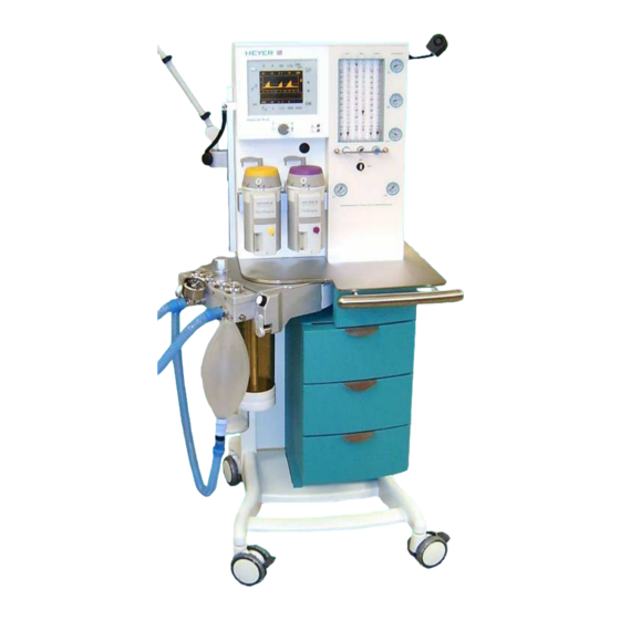
Heyer Modular+ Service Manual (114 pages)
Anesthesia System
Brand:
Heyer
| Category:
Medical Equipment
| Size: 2 MB
Table of Contents
Table of Contents
3
Table of Figures
6
1 General Information
7
Guidelines
7
Product Improvements
7
Manufacturer's Liability
7
Manufacturer's Specification
8
Updating Status
8
Carl-Heyer-Strasse
8
Warning, Precautions and Notes
9
Warnings
9
Precautions
10
Notes
11
2 Theory of Operation
13
Microprocessor-Controlled Ventilator
13
Patient Module
13
Gas Conditioning Unit
13
The Ventilator Unit
13
Adjustable Alarms
13
Fresh Gas Decoupling
14
Max Limiting on Alarm Violation
14
Compliance Compensation
14
Electrical Supply
15
Electrical Components
16
Power Supply Module
17
Connectors on Power Supply Board AVM 2-1
18
Fuses on Power Supply Board AVM 2-1
19
Charging / Discharging Control for the Battery
20
Status Indicators of Battery Control
20
Module 1
21
Connectors on Module 1
22
Ventilator Module 2, AVM 3-1 and AVM 3-2
23
Parts List Module 2
24
Connectors on Module 2
24
Plug Connectors on Board AVM 3-1
24
Plug Connectors on Board AVM3-2
25
Display
25
Battery
25
Ventilator Pneumatic
26
Ventilator Pneumatic Drive
27
HP Pressure Reducer
27
LP- Double Stage Pressure Reducer
27
Solenoid Valves MV1 to MV4
27
Pneumatic Driving Module
28
Flow Metering Module
28
Tube Color Coding
28
The Patient Module (Circle System)
29
Front and Back Side View on the Patient Module
29
Bottom and Back Side View on the Patient Module
30
Functional Representations of the Patient Module
31
CMV Mode, Inspiration
32
CMV Mode, Expiration
33
Manual Mode, Inspiration
34
Manual Mode, Expiration
35
Spontaneous Mode, Inspiration
36
Spontaneous Mode, Expiration
37
Components of the Patient Module
38
Airway Pressure Relief Valve
38
CO Absorber
38
Diaphragm Valves
38
Inspiratory and Expiratory Valves
38
Manual Respiration Bag / Reservoir
38
Room Air Valve
38
Ventilation Bellows System
38
CMV Adult, EXPIRATION and PEEP
39
CMV Child / Adult Mode, INSPIRATION
39
CMV Child / Adult, EXPIRATION
39
Machine off or Ventilator in Standby
39
Manual / Spontaneous Mode, INSPIRATION and EXPIRATION
39
Status of the Diaphragm Valves
39
Compliance Test Patient Module
40
Leak Test Patient Module and Fresh Gas Module
40
3 Repair Information
41
Introduction
41
Warnings and Precautions
41
Precautions
41
Warnings
41
Troubleshooting Guidelines
42
Troubleshooting Charts
42
Error Messages During Ventilation
42
Alarm Messages During the Compliance Test, Leak Test and O2 Calibration
46
Messages During the System Tests
47
Symptoms of Fuse Failures
49
Required Tools
50
Disassembly Instructions
50
Connecting and Disconnecting Vaporizers
50
Removing the Compressed Gas Tanks (PIN-Index)
50
Removing the Patient Module
51
Removing the Bellows and Dome System
51
Removing the CO Absorber Canister
51
Removing the Airway Pressure Limiting Valve (APL)
51
Inspecting/Replacing the Decoupling, Bellow and Expiratory Valves
52
Disassembling the Room Air, Inspiration and Expiration Valves
52
Removing the Gas Block Module
52
Removing the Flow Tubes
52
Removing the Pressure Gauges
53
Removing the Module 2 Circuit Board Set
53
Removing Module1 Circuit Board Set
53
Removing the Power Supply Module
53
Removing Internal Regulators, Proportional Valve and Flow Divider
54
4 Maintenance and Calibration
55
Introduction
55
Calibration Warnings and Precautions
55
Test Procedure
56
General
56
Inspecting/Replacing Consumable Parts
56
Fig. 16 Patient Module, Front View
57
Fig. 17 Patient Module, Top View
58
Fig. 18 Supply Inlet Filters and Water Traps
59
Power Supply Checks
61
Functional Tests
62
Pneumatic Tests
62
Alarm Tests
63
Fig. 21 O2 Whistle Adjustment (Appearance May Differ Due to Different Configuration Options)
64
Electrical Tests
65
Service Software
66
Key Code Access
67
Navigation
68
Fig. 25 Test Menu Screen
69
System Testing
70
Fig. 27 Docking Station, Start/ Stop Switches
71
Fig. 29 Proportional Valve Test Screen
75
Fig. 31 Solenoid Valves MV-1 MV-4 Test Screen
76
Fig. 32 Docking Station Valve Connectors
77
Fig. 33 Power and Heater Control Screen
78
Coefficient Programming
79
O 2 Sensor Calibration
79
P1 Pressure Sensor Calibration
81
P2 Pressure Sensor Calibration
83
Temperature Sensor Calibration
85
Proportional Valve Calibration
87
Fig. 38 Proportional Valve Calibration Screen
88
Fig. 40 Pressure Regulator for the Driving Gas with Test Port
89
Fig. 41 Adjustment Screw on Top of the Flow Divider
91
Internal Flow Sensor Calibration
92
Characteristic of the Proportional Valve
94
External Flow Sensor Calibration
96
Fig. 45 How to Measure the Voltages U1 and U2
98
5 Preventive Maintenance
99
Month Service Interval
99
Month Service Interval
100
Cleaning
101
Cleaning and Disinfecting the Apparatus
101
Cleaning and Sterilizing the Patient Module
101
Battery Replacement and Maintenance
101
Battery Replacement
101
Battery Maintenance
101
6 Order Information
103
Advertisement
Advertisement
Related Products
Heyer Modular
Heyer AGFS
Heyer iTernIS ADV
Heyer LUVAR
Heyer LUVAR A
Heyer LUVAR STA
Heyer Narkomat +
Heyer Pasithec
Heyer Categories
Medical Equipment
Switch
Disc Duplicator
More Heyer Manuals
Login
Sign In
OR
Sign in with Facebook
Sign in with Google
Upload manual
Upload from disk
Upload from URL