Table of Contents
Advertisement
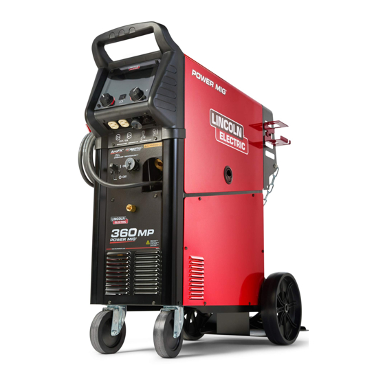
Operator's Manual
Power MIG
Register your machine:
www.lincolnelectric.com/register
Authorized Service and Distributor Locator:
www.lincolnelectric.com/locator
Save for future reference
Date Purchased
Code: (ex: 10859)
Serial: (ex: U1060512345)
IM10547
| Issue D ate Oct-19
© Lincoln Global, Inc. All Rights Reserved.
360MP
®
For use with machines having Code Numbers:
12910
Need Help? Call 1.888.935.3877
to talk to a Service Representative
Hours of Operation:
8:00 AM to 6:00 PM (ET) Mon. thru Fri.
After hours?
Use "Ask the Experts" at lincolnelectric.com
A Lincoln Service Representative will contact you
no later than the following business day.
For Service outside the USA:
Email: globalservice@lincolnelectric.com
Advertisement
Table of Contents

Subscribe to Our Youtube Channel
Related Manuals for Lincoln Electric Power MIG 360MP


Summary of Contents for Lincoln Electric Power MIG 360MP
- Page 1 Operator’s Manual Power MIG 360MP ® For use with machines having Code Numbers: 12910 Register your machine: Need Help? Call 1.888.935.3877 to talk to a Service Representative www.lincolnelectric.com/register Authorized Service and Distributor Locator: Hours of Operation: www.lincolnelectric.com/locator 8:00 AM to 6:00 PM (ET) Mon. thru Fri. Save for future reference After hours? Use “Ask the Experts”...
- Page 2 THANK YOU FOR SELECTING A QUALITY PRODUCT BY KEEP YOUR HEAD OUT OF THE FUMES. DON’T get too close to the arc. LINCOLN ELEC TRIC. Use corrective lenses if necessary to stay a reasonable distance away from the arc. READ and obey the Safety Data PLEASE EXAMINE CARTON AND EQUIPMENT FOR Sheet (SDS) and the warning label DAMAGE IMMEDIATELY...
- Page 3 W117.2-1974. A Free copy of “Arc Welding Safety” booklet E205 is available from the Lincoln Electric Company, 2.d. All welders should use the following procedures in order to 22801 St. Clair Avenue, Cleveland, Ohio 44117-1199.
- Page 4 SAFETY ELECTRIC SHOCK ARC RAYS CAN BURN. CAN KILL. 3.a. The electrode and work (or ground) circuits are 4.a. Use a shield with the proper filter and cover plates to protect your electrically “hot” when the welder is on. Do eyes from sparks and the rays of the arc when welding or not touch these “hot”...
- Page 5 SAFETY WELDING AND CUTTING CYLINDER MAY EXPLODE IF SPARKS CAN CAUSE DAMAGED. FIRE OR EXPLOSION. 7.a. Use only compressed gas cylinders containing the correct shielding gas for the process used 6.a. Remove fire hazards from the welding area. If and properly operating regulators designed for this is not possible, cover them to prevent the welding sparks the gas and pressure used.
-
Page 6: Table Of Contents
TABLE OF CONTENTS INSTALLATION .............................SECTION A ® TECHNICAL SPECIFICATIONS – POWER MIG 360MP....................A.1 INSTALLATION ................................A.2 ® UNCRATING THE POWER MIG 360MP ........................A.2 LOCATION ................................A.2 TILTING ................................A.2 OUTPUT POLARITY CONNECTIONS ..........................A.3 INPUT POWER, GROUNDING AND CONNECTION DIAGRAM ..................A.3 GUN AND CABLE INSTALLATION..........................A.4 SHIELDING GAS................................A.5 AUXILIARY POWER RECEPTACLES ..........................A.5 OPERATION ..............................SECTION B... - Page 7 ® POWER MIG 360MP INSTALLATION ® TECHNICAL SPECIFICATIONS – POWER MIG 360MP INPUT-SINGLE PHASE ONLY Input Voltage ± 10% Effective Input Amperes 208/230/460/575 Volts 55/50/25/20 50/60 Hz RATED OUTPUT Input Voltage/ GMAW GTAW-DC SMAW Phase/Frequency 100% 100% 100% 208/230/460/575/ Amps Amps Amps Amps...
-
Page 8: Installation
® POWER MIG 360MP INSTALLATION INSTALLATION ® UNCRATING THE POWER MIG 360MP Cut banding and lift off cardboard carton. Cut banding holding the Read entire installation section before starting machine to the skid. Remove foam and corrugated packing installation. material. Untape accessories from Gas Bottle Platform. Unscrew the two wood screws (at the Gas Bottle Platform) holding the machine to the skid. -
Page 9: Output Polarity Connections
® POWER MIG 360MP INSTALLATION FIGURE A.1 OUTPUT POLARITY CONNECTIONS The welder, as shipped from the factory, is connected for electrode positive (+) polarity. This is the normal polarity for GMAW. If negative (–) polarity is required, interchange the connection of the two cables located in the wire drive compartment near the front panel. -
Page 10: Gun And Cable Installation
® POWER MIG 360MP INSTALLATION FIGURE A.5 GUN AND CABLE INSTALLATION The Magnum® PRO Curve 300 gun and cable provided with the ® POWER MIG 360MP is factory installed with a liner for .035- .045" (0.9-1.1 mm) electrode and an .035" (0.9 mm) contact tip. Install the .045”... -
Page 11: Shielding Gas
® POWER MIG 360MP INSTALLATION WARNING SHIELDING GAS For necessary processes. Never stand directly in front of or behind the flow regulator when opening the cylinder valve. Always stand to one side. Customer must provide cylinder of appropriate type shielding gas for the process being used. -
Page 12: Operation
® POWER MIG 360MP OPERATION OPERATION WELDING CAPABILITY SAFETY PRECAUTIONS ® The POWER MIG 360MP is rated at 350 amps @ 31.5 volts, at a Read this entire section of operating instructions before operating 40% duty cycle based on a ten minute cycle time for GMAW the machine. -
Page 13: Case Front Controls
® POWER MIG 360MP OPERATION CASE FRONT CONTROLS CASE BACK CONTROLS FIGURE B.1 FIGURE B.2 1. Color LED Screen – Permits visualization of welding process and 1. Decal – Serial number. parameters. The screen features a replaceable screen shield for 2. -
Page 14: Internal Controls
® POWER MIG 360MP OPERATION INTERNAL CONTROLS FIGURE B.3 1. Wire Drive Tension Pressure Adjustment – Permits increasing or decreasing the pressure applied to the top drive roll. 2. Wire Drive Spindle – Supports a 4-inch or 8-inch spool of wire. The center wing-nut can be adjusted to increase tension on the wire. -
Page 15: Ready.set.weld
® POWER MIG 360MP OPERATION Select wave form type (If Applicable) READY.SET.WELD™ The POWER MIG ® 360 comes equipped with ™ Ready.Set.Weld which allows the user to easily select the correct welding procedure per their application. Select your process Standard CV Pulse Back Home... - Page 16 ® POWER MIG 360MP INSTALLATION Stick (SMAW) WELDING PROCESSES MENU Select between Soft or Crisp arc Manual MIG Soft: Has a less penetrating arc characteristic. For low hydrogen types of electrodes (E7018, E8018, E9018, etc) a softer arc is See section on installing wire and setting up MIG gun. usually desirable.
-
Page 17: Weld Settings
® POWER MIG 360MP OPERATION PREFLOW- The Preflow setting allows a time to be selected for shielding gas to flow after the trigger is pulled WELD SETTINGS and prior to wire feeding and establishing an arc. The POWER MIG ® 360 allows the user to make adjustments PULSE- Selecting this mode allows the user to toggle to the advanced weld parameters via the Weld Settings... -
Page 18: Arc Control
® POWER MIG 360MP OPERATION ARC CONTROL The POWER Mig ® 360 allows the user to make adjusts to the welding arc via the Weld Settings screen. Options available are dependent on the welding process you have selected. The table below lists the arc controls available per welding process. -
Page 19: Special Welding Processes
® POWER MIG 360MP OPERATION Current Calibration - Selecting current calibration mode PULSE-ON-PULSE ® allows a service technician the ability to calibrate the Pulse on Pulse™ is a Lincoln process specifically designed for use machine's output current. See Maintenance section for more in welding relatively thin (less than 1/4"... - Page 20 ® POWER MIG 360MP OPERATION Power Mode ® ® The Power Mode process was developed by Lincoln to maintain a stable and smooth arc at low procedure settings which are needed to weld thin metal without pop-outs or burning-through. For Aluminum welding, it provides excellent control and the ability to maintain constant arc length.
-
Page 21: Wire Size Conversion Parts
® POWER MIG 360MP OPERATION Drive Rolls WIRE REEL LOADING - READI REELS, SPOOLS OR COILS The drive rolls installed with the POWER MIG ® 360MP have two To Mount a 30 Lb. (14 kg) Readi-Reel Package (Using the Molded grooves one for .035”... -
Page 22: To Start The Welder
® POWER MIG 360MP OPERATION To Mount 10 to 44 Lb. (4.5-20 kg) Spools (12"/300 mm Diameter) or 14Lb.(6 Kg) Innershield Coils: IDLE ROLL PRESSURE SETTING (For 13-14 lb. (6 Kg) Innershield coils, a K435 Coil Adapter must WARNING be used). ELECTRIC SHOCK can kill. -
Page 23: Wire Drive Configuration
® POWER MIG 360MP OPERATION MAKING A WELD WIRE DRIVE CONFIGURATION CHANGING THE GUN RECEIVER BUSHING 1. Check that the electrode polarity is correct for the process being used, then turn the power switch ON. Tools required: 2. Set desired arc voltage and wire speed for the particular •... -
Page 24: Avoiding Wire Feeding Problems
® POWER MIG 360MP OPERATION AVOIDING WIRE FEEDING PROBLEMS Wire feeding problems can be avoided by observing the following gun handling procedures: • Do not kink or pull cable around sharp corners. • Keep the gun cable as straight as possible when welding or loading electrode through cable. -
Page 25: Options / Accessories
® POWER MIG 360MP ACCESSORIES OPTIONS / ACCESSORIES ALTERNATIVE MAGNUM GMAW GUN AND CABLE ASSEMBLIES DRIVE ROLL KITS ® The following Magnum PRO 250L gun and cable assembly is ® separately available for use with the POWER MIG 360MP. Each is Refer to Table C.1 for various drive roll kits that are available for rated 200 amps 60% duty cycle (or 250 amps 40% duty) and is ®... -
Page 26: Maintenance
® POWER MIG 360MP MAINTENANCE MAINTENANCE CONTACT TIP AND GAS NOZZLE INSTALLATION Safety Precautions 1. Choose the correct size contact tip for the electrode being used (wire size is stenciled on the side of the contact tip) and WARNING screw it snugly into the gas diffuser. 2. -
Page 27: Liner Removal, Installation And Trimming
® POWER MIG 360MP MAINTENANCE LINER REMOVAL, INSTALLATION AND TRIMMING (See Figure D.1) NOTE: The variation in cable lengths prevents the interchange- ability of liners between guns. Once a liner has been cut for a particular gun, it should not be installed in another gun unless it can meet the liner cutoff length requirement. -
Page 28: Calibration
® POWER MIG 360MP MAINTENANCE Current Calibration Calibrating Spool Gun 1. Access the Current Calibration mode from the Configuration 1. To calibrate the spool gun, select Spool Gun from the Weld menu. Process selection screen. 2. Connect work and output leads to a grid load. Set grid load 2. -
Page 29: Legacy Weld Modes
LIST OF LEGACY WELD MODES Mode Process Procedure Wire Size Wire Type Gas Type ArcControl SMAW Stick General Purpose Arc Force SMAW Stick Crisp Arc Force GTAW Touch Start TIG GMAW CV MIG Pinch FCAW-S CV Flux Core Self Shield Pinch FCAW-G CV Flux Core Gas Shield... -
Page 30: Troubleshooting
® POWER MIG 360MP TROUBLESHOOTING TROUBLESHOOTING HOW TO USE TROUBLESHOOTING GUIDE WARNING Service and Repair should only be performed by Lincoln Electric Factory Trained Personnel. Unauthorized repairs performed on this equipment may result in danger to the technician and machine operator and will invalidate your factory warranty. - Page 31 ® POWER MIG 360MP TROUBLESHOOTING Observe all Safety Guidelines detailed throughout this manual PROBLEMS POSSIBLE AREAS OF RECOMMENDED (SYMPTOMS) MISADJUSTMENTS(S) COURSE OF ACTION OUTPUT PROBLEMS Major physical or electrical damage Do not plug in machine or turn it on. Contact your is evident.
- Page 32 ® POWER MIG 360MP TROUBLESHOOTING Observe all Safety Guidelines detailed throughout this manual PROBLEMS POSSIBLE AREAS OF RECOMMENDED (SYMPTOMS) MISADJUSTMENTS(S) COURSE OF ACTION Output voltage and wire feed is present 1. Remove gun assembly from machine. If If all recommended possible areas of when gun trigger is not pulled (not problem is solved, gun assembly is misadjustment have been checked and the...
- Page 33 ® POWER MIG 360MP TROUBLESHOOTING Observe all Safety Guidelines detailed throughout this manual PROBLEMS POSSIBLE AREAS OF RECOMMENDED (SYMPTOMS) MISADJUSTMENTS(S) COURSE OF ACTION The wire feed stops while welding. When 1. Check the wire feed drive rolls and motor trigger is released and pulled again the for smooth operation.
- Page 34 Observe all Safety Guidelines detailed throughout this manual POWER MIG ® 360MP TROUBLESHOOTING PROBLEMS POSSIBLE RECOMMENDED (SYMPTOMS) CAUSE COURSE OF ACTION PUSH PULL WIRE FEEDING PROBLEMS While loading wire, the rear drive rolls stop 1. Check torch cable for kinks. Torch cable while pushing wire through the torch.
- Page 35 POWER MIG ® 360MP TROUBLESHOOTING Observe all Safety Guidelines detailed throughout this manual PROBLEMS POSSIBLE RECOMMENDED (SYMPTOMS) CAUSE COURSE OF ACTION PUSH PULL WIRE FEEDING PROBLEMS While loading wire the wire bird nests if the 1. Straighten the first six inches of the wire wire misses the outlet guide while shooting before feeding it into the rear wire drive.
- Page 36 POWER MIG ® 360MP TROUBLESHOOTING Observe all Safety Guidelines detailed throughout this manual PROBLEMS POSSIBLE RECOMMENDED (SYMPTOMS) CAUSE COURSE OF ACTION PUSH PULL WIRE FEEDING PROBLEMS During Welding the wire continues to burn 1. Check to see that the spindle brake is back to the tip.
-
Page 38: Diagrams
® DIAGRAMS POWER MIG... - Page 39 This page has been left blank intentionally.
- Page 40 This page has been left blank intentionally.
- Page 41 This page has been left blank intentionally.
- Page 42 WARNING Do not touch electrically live parts or Keep flammable materials away. Wear eye, ear and body protection. electrode with skin or wet clothing. Insulate yourself from work and AVISO DE ground. Spanish PRECAuCION No toque las partes o los electrodos Mantenga el material combustible Protéjase los ojos, los oídos y el bajo carga con la piel o ropa moja-...
- Page 43 WARNING Keep your head out of fumes. Turn power off before servicing. Do not operate with panel open or Use ventilation or exhaust to guards off. remove fumes from breathing zone. AVISO DE Spanish PRECAuCION Los humos fuera de la zona de res- Desconectar el cable de ali- No operar con panel abierto o piración.
- Page 44 We respond to our customers based on the best information in our possession at that time. Lincoln Electric is not in a position to warrant or guarantee such advice, and assumes no liability, with respect to such information or advice.
Need help?
Do you have a question about the Power MIG 360MP and is the answer not in the manual?
Questions and answers