Table of Contents
Advertisement
Operator's Manual
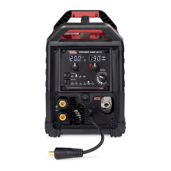
POWER MIG 211
Register your machine:
www.lincolnelectric.com/register
Authorized Service and Distributor Locator:
www.lincolnelectric.com/locator
Save for future reference
Date Purchased
Code: (ex: 10859)
Serial: (ex: U1060512345)
IM10644
| Issue Date Apr - 22
© Lincoln Global, Inc. All Rights Reserved.
®
i
For use with machines having Code Numbers:
13214
Advertisement
Table of Contents

Related Manuals for Lincoln Electric POWER MIG 211i


Summary of Contents for Lincoln Electric POWER MIG 211i
- Page 1 Operator’s Manual POWER MIG 211 ® For use with machines having Code Numbers: 13214 Register your machine: www.lincolnelectric.com/register Authorized Service and Distributor Locator: www.lincolnelectric.com/locator Save for future reference Date Purchased Code: (ex: 10859) Serial: (ex: U1060512345) IM10644 | Issue Date Apr - 22 ©...
-
Page 2: Safety Depends On You
THANK YOU FOR SELECTING A QUALITY PRODUCT BY KEEP YOUR HEAD OUT OF THE FUMES. DON’T get too close to the arc. LINCOLN ELEC TRIC. Use corrective lenses if necessary to stay a reasonable distance away from the arc. READ and obey the Safety Data PLEASE EXAMINE CARTON AND EQUIPMENT FOR Sheet (SDS) and the warning label DAMAGE IMMEDIATELY... -
Page 3: Section A: Warnings
P.O. Box 351040, Miami, Florida 33135 or CSA Standard W117.2. A Free copy of “Arc Welding Safety” booklet E205 2.a. Electric current owing through any conductor is available from the Lincoln Electric Company, 22801 causes localized Electric and Magnetic Fields (EMF). St. Clair Avenue, Cleveland, Ohio 44117-1199. -
Page 4: Electric Shock Can Kill
SAFETY ELECTRIC SHOCK ARC RAYS CAN BURN. CAN KILL. 3.a. The electrode and work (or ground) circuits are 4.a. Use a shield with the proper filter and cover plates to protect your electrically “hot” when the welder is on. Do eyes from sparks and the rays of the arc when welding or not touch these “hot”... - Page 5 SAFETY WELDING AND CUTTING CYLINDER MAY EXPLODE IF SPARKS CAN CAUSE DAMAGED. FIRE OR EXPLOSION. 7.a. Use only compressed gas cylinders containing the correct shielding gas for the process used 6.a. Remove fire hazards from the welding area. If and properly operating regulators designed for this is not possible, cover them to prevent the welding sparks the gas and pressure used.
- Page 6 POWER MIG 211i TABLE OF CONTENTS ®...
-
Page 7: Product Description
POWER MIG 211i PRODUCT DESCRIPTION ® PRODUCT DESCRIPTION PRODUCT SUMMARY The Power MIG® 211i is a constant voltage DC welding machine rated for 175 amps, 22.8 volts at a 30% duty cycle. The Power MIG® units are intended for fabrication, maintenance, home, and autobody shops. -
Page 8: Recommended Processes And Equipment
POWER MIG 211i PRODUCT DESCRIPTION ® RECOMMENDED PROCESSES AND EQUIPMENT COMMON EQUIPMENT PACKAGES RECOMMENDED PROCESSES The Power MIG® 21 is recommended for GMAW FCAW processes. The machine can support 4 inch and 8 inch spools of wire BASIC PACKAGE: for GMAW and FCAW welding. The machine is intended for the... -
Page 9: Specifications
POWER MIG 211i DESIGN ® DESIGN SPECIFICATIONS POWER SOURCES - INPUT VOLTAGE AND CURRENT WELDING PROCESSES PROCESS ELECTRODE DIAMETER RANGE OUTPUT RANGE WIRE FEED DUTY CYCLE INPUT VOLTAGE INPUT AMPERES IDLE AMPS (OUTPUT) (AMPERES) SPEED RANGE 22.5A GMAW .025-.035” 20-211 50-500 IPM ( 5A / 22. -
Page 10: Regulatory Requirements
POWER MIG 211i DESIGN ® REGULATORY REQUIREMENTS MODEL MARKET CONFORMITY STANDARD MARK K6080-1 US AND cCSA IEC 60974-1 CANADA IEC 60974-5 INTENDED RATING For Internal IP21S Use Only DESIGN FEATURES • Efficient Inverter power topology- reduces power consumption and reduces the mass of the unit when compared with traditional SCR based machines. -
Page 11: Case Front Control Descriptions
POWER MIG 211i DESIGN ® CASE FRONT CONTROLS FIGURE A.1 CASE FRONT CONTROL DESCRIPTIONS 7. Power Switch - Permits turning the machine on or off. 1. Adjustment Knob – Permits selecting wire feed speed for MIG & FCAW welding. 8. Gun Connection - Permits attachment of a MIG welding gun. -
Page 12: Internal Controls
POWER MIG 211i DESIGN ® CASE BACK INTERNAL CONTROLS FIGURE A.2 FIGURE A.3 INTERNAL CONTROLS DESCRIPTION 1. Spool Gun Switch – Permits toggling between standard push gun welding with the Magnum® Pro 100L or aluminum welding with the Magnum® Pro 100SG Spool Gun. -
Page 13: Installation
Failure to observe these precautions can result in excessive operating temperatures and nuisance thermal trips. PROPER HANDLING The Power MIG 211i should be lifted by the center handle or by Observe all safety information throughout this grasping both the front and back handles simultaneously. The manual. -
Page 14: Gun And Cable Installation
POWER MIG 211i INSTALLATION ® CONNECTION DIAGRAM(S), SYSTEM DO NOT ATTACH THE REGULATOR IF OIL, GREASE OR DAMAGE IS PRESENT! Inform your gas supplier of this condition. Oil or grease in GUN AND CABLE INSTALLATION the presence of high pressure oxygen is explosive. -
Page 15: Electrode And Work Connections
POWER MIG 211i INSTALLATION ® PROCEDURE FOR CHANGING DRIVE AND IDLE ROLL SETS ELECTRODE AND WORK CONNECTIONS 1. Turn off the power source. OUTPUT POLARITY CONNECTIONS 2. Release the pressure on the idle roll by swinging the adjustable The Power MIG® 211i features a short lead protruding from the pressure arm down toward the back of the machine. -
Page 16: Operation
POWER MIG 211i OPERATION ® OPERATION GRAPHIC SYMBOLS USED IN THIS MANUAL OR BY THIS MACHINE POWER-UP SEQUENCE 1. Check that the electrode polarity is correct for the process being 3. Press the trigger to feed the wire electrode through the gun and used, then turn the power switch ON. -
Page 17: Input Line Voltage Variations
POWER MIG 211i OPERATION ® The duty cycle is the “on” time (based on a 10 minute interval) the user can weld with the machine at a specific output without causing a thermal trip. Example: 30% duty cycle means welding at the speci ed output for 3 constant minutes and needing 7 minutes of “off”... -
Page 18: General Options / Accessories
POWER MIG 211i ACCESSORIES ® GENERAL OPTIONS / ACCESSORIES Description Part Number .025 Magnum Pro Tapered KP2744-.025T Contact Tip .030 Magnum Pro Tapered KP2744-.030T Contact Tip .035 Magnum Pro Tapered KP2744-.035T Contact Tip .045 Magnum Pro Tapered KP2744-.045T Contact Tip .025-.035 Gun Liner... -
Page 19: Routine Maintenance
POWER MIG 211i MAINTENANCE ® ROUTINE MAINTENANCE CAUTION PERIODIC MAINTENANCE WARNING LINER REMOVAL, INSTALLATION AND TRIMMING INSTRUCTIONS FOR MAGNUM PRO 100L NOTE: The variation in cable lengths prevents interchanging of liners Before carrying out service, maintenance and/or between guns. Once a liner has been cut for a particular gun, it repair jobs, fully disconnect power to the machine. - Page 20 HOW TO USE TROUBLESHOOTING GUIDE WARNING Service and Repair should only be performed by Lincoln Electric Factory Trained Personnel. Unauthorized repairs performed on this equipment may result in danger to the technician and machine operator and will invalidate your factory warranty.
-
Page 21: Troubleshooting
POWER MIG 211i TROUBLE SHOOTING ® Observe all Safety Guidelines detailed throughout this manual PROBLEMS POSSIBLE RECOMMENDED (SYMPTOMS) CAUSE COURSE OF ACTION Major physical or electrical damage is “Do not Plug in machine or turn it on.” evident. Contact your local Authorized Field Service Facility. - Page 22 POWER MIG 211i TROUBLE SHOOTING ® Observe all Safety Guidelines detailed throughout this manual PROBLEMS POSSIBLE RECOMMENDED (SYMPTOMS) CAUSE COURSE OF ACTION Arc is unstable - Poor starting. 1. Check for correct input voltage to machine. 2. Check for proper electrode polarity for process.
- Page 23 POWER MIG 211i DIAGRAMS ®...
- Page 24 POWER MIG 211i DIAGRAMS ®...
- Page 25 This page intentionally left blank.
- Page 26 WARNING Do not touch electrically live parts or Keep flammable materials away. Wear eye, ear and body protection. electrode with skin or wet clothing. Insulate yourself from work and AVISO DE ground. Spanish PRECAuCION No toque las partes o los electrodos Mantenga el material combustible Protéjase los ojos, los oídos y el bajo carga con la piel o ropa moja-...
- Page 27 WARNING Keep your head out of fumes. Turn power off before servicing. Do not operate with panel open or Use ventilation or exhaust to guards off. remove fumes from breathing zone. AVISO DE Spanish PRECAuCION Los humos fuera de la zona de res- Desconectar el cable de ali- No operar con panel abierto o piración.
- Page 28 Lincoln Electric is solely within the control of, and remains the sole responsibility of the customer. Many variables beyond the control of Lincoln Electric affect the results obtained in applying...
Need help?
Do you have a question about the POWER MIG 211i and is the answer not in the manual?
Questions and answers
wwhat is the difference in Migc25 and Migc100