
Related Manuals for Welch Allyn ELI 150


Summary of Contents for Welch Allyn ELI 150
- Page 1 ELI 150 Service Manual Manufactured by Welch Allyn, Inc. Skaneateles Falls, NY U.S.A CAUTION: Federal law restricts this device to sale by or on the order of a physician...
- Page 2 © 2019 Welch Allyn This document contains confidential information that belongs to Welch Allyn, Inc. No part of this document may be transmitted, reproduced, used, or disclosed outside of the receiving organization without the express written consent of Welch Allyn, Inc. Welch Allyn is a registered trademark of Welch Allyn, Inc. AM12, ELI, VERITAS, and WAM are trademarks of Welch Allyn, Inc.
- Page 4 • Assembly operations, extensions, readjustments, modifications or repairs are carried out only by persons authorized by Mortara Instrument, Inc. • The device (ELI 150) is used in accordance with the instructions for use. Responsibility of the Customer The user of this product is responsible for ensuring the implementation of a satisfactory maintenance schedule. Failure to do so may cause undue failure and possible health hazards.
-
Page 5: Warranty Information
Warranty Information Your Mortara Warranty MORTARA INSTRUMENT, INC. (hereinafter referred to as “Mortara”) hereby warrants that Mortara products (hereinafter referred to as “Products”) shall be free from defects in material and workmanship under normal use, service and maintenance for the warranty period of such Product from Mortara or an authorized distributor or representative of Mortara. Normal use, service and maintenance means operation and maintenance in accordance with appropriate instructions and/or information guides. - Page 6 UL 2601-1, IEC 601-1 and IEC 601-2-25. Patient cables intended for use with the ELI 150 include series resistance (9 Kohm minimum) in each lead for defibrillation protection. Patient cables should be checked for cracks or breakage prior to use.
- Page 7 IEC 60601-1-1, and leakage currents should be measured to confirm no electric shock hazard exists. The ELI 150 has not been designed for use with high-frequency (HF) surgical equipment and does not provide a protective means against hazards to the patient.
- Page 8 There is no known safety hazard if other equipment, such as pacemakers or other stimulators, are used simultaneously with the ELI 150; however, disturbance to the signal may occur. If the ECG amplifier input is out of normal operating range, the display will indicate a lead fail for the lead(s) where this...
- Page 9 After operating the ELI 150 using battery power, always reconnect the power cord. This ensures that the batteries will be automatically recharged for the next time you use the ELI 150. A light will illuminate, next to the on/off switch, indicating that the unit is charging.
- Page 10 viii...
-
Page 11: Table Of Contents
Table of Contents General Service Manual Purpose ....................... 1-1 User Safety Information ......................1-1 Periodic Safety Inspections ..................1-1 Proper Power Cord ....................1-1 Proper Fuse ......................1-1 Do Not Operate in Explosive Atmospheres .............. 1-1 Use Only Safe Methods of Interconnection .............. 1-1 Do Not Mount Product above Patient ............... - Page 12 Interpretation Option ....................3.10 Reasons ........................3-10 Configuration Page 3 ......................3-11 Append ......................... 3-11 Number of Copies ......................3-11 ECG Retrieved ......................3-11 Delete Rule ........................3-11 Storage Sensitivity ....................... 3-12 Auto Save ECG ......................3-12 Auto Print ECG ......................3-12 Baud Rate ........................
- Page 13 Technical Description Introduction ..........................5-1 ELI 250/210 Block Diagram ....................5-2 Main System Board ....................... 5-3 Front End Board ........................5-3 Patient Input........................... 5-4 ELI 250/210 Specifications ....................5-5 Parts List ..........................5-6 Troubleshooting and Testing Introduction ..........................6-1 Troubleshooting ........................
-
Page 15: General
General Service Manual Purpose The purpose of this manual is to supply information to service personnel so they can maintain the ELI 150 Interpretive and Non-Interpretive Electrocardiograph at the assembly and subassembly level. Although the manual includes parts lists, mechanical assembly parts, and printed circuit board information, it is intended to function primarily as a guide to preventative and corrective maintenance and electrical repairs considered field repairable. -
Page 16: Sterilizing This Product
Do not sterilize this product or any accessories unless specifically directed by the manufacturer. Sterilization and sterilization environments can seriously damage many components and accessories. Liquid Spills Do not set beverages or other liquids on or near the ELI 150, and/or optional equipment. Product Information See Section 1 of Operator's Manual... -
Page 17: Maintenance And Cleaning
Removal of the battery fuse will not cause a loss of ECGs or of the configuration. This information is stored in FLASH memory. Introduction This section provides servicing and maintenance instructions for the ELI 150 interpretive electrocardiograph. Subsequent parts of this section are disassembly, inspection techniques, cleaning techniques, and installation. Recommended Cleaning Supplies ... -
Page 18: Cleaning And Inspection Techniques
Printed Circuit Board Cleaning The printed circuit board assemblies in the ELI 150 system contain static sensitive devices. Use special handling procedures to prevent damage due to ESD. Clean assembled parts with a vacuum cleaner or low pressure compressed air (30 psi). Take care when cleaning printed circuit boards that wires or component leads are not bent back and forth in such a manner as to weaken them and cause them to eventually break. -
Page 19: Metallic And Plastic Parts Cleaning
Section 2 Metallic and Plastic Parts Cleaning CAUTION Do not wipe over surfaces of nameplates or labels with abrasive cleaners or materials, as this will eventually wear away the nameplate information. Do not use solvents to clean plastic parts. Brush all surfaces and parts with a nonmetallic, soft bristle brush. Wipe metal surfaces with soft, nonabrasive cloth dampened with isopropyl alcohol. -
Page 20: Exterior Inspection
ELI 150 Exterior Inspection Visually inspect the entire instrument for wear, maintenance damage, corrosion, deterioration, and damage resulting from dropping. Interior Visual Inspection Check all connectors for loose, bent or corroded contact points Check wire, harnesses and cables for signs of wear or deterioration. -
Page 21: System Settings
Once you set these default conditions, you will rarely need to use the configuration screens again. When you apply power to the ELI 150, it will operate according to the settings you have selected. To access the configuration menus: ... - Page 22 ELI 150 From the Set Time/Date screen, simultaneously press (SHIFT) + ALT + C. The first configuration screen will appear. Notice the page indicator in the upper right hand corner on each screen. NOTES: Use Page (F4) to toggle through the configuration pages.
-
Page 23: Summary Of Configuration Menus
Section 3 Summary of Configuration Menus Configuration Definition Configuration Screen Parameter Software Version The firmware version of the unit Screen One Cart Number User-defined (4 digits; 0 to 9999) Screen One Site Number User-defined (4 digits; 0 to 4095) Screen One Site Name User-defined (up to 30 alphanumeric characters) Screen One... - Page 24 ELI 150 Append Unconfirmed Report, Reviewed by, Blank Screen Three #of copies 0 - 9 Screen Three #ECGs retrieved 0 - 7 Screen Three...
- Page 25 Section 3 Configuration Definition Configuration Screen Parameter Delete Rule Post plot, post transmit, post plot/xmt Screen Three Storage Sensitivity Normal or High Screen Three Auto-save ECG Yes or No Screen Three Auto-print ECG Yes or No Screen Three Baud Rate Serial Baud Rates: 9600, 19200, 38400, 57600, or Screen Three 115200...
- Page 26 ELI 150 3 + 3 Rhythm Lead 2 V1-V6, I, II, III, aVR, aVL, aVF Screen Five 3 + 3 Rhythm Lead 3 V1-V6, I, II, III, aVR, aVL, aVF Screen Five XMT Media RS232, Modem, GSM, LAN, External Modem...
-
Page 27: Configuration
Cart numbers indicate which electrocardiograph transmitted a particular ECG. Site Number This option identifies the site of your ELI 150. Site numbers designate the hospital, clinic, or institution for ECG records stored in a Mortara Instrument, E-Scribe data management system and must be defined for transmitting and retrieving ECGs from the data management system. -
Page 28: Language
ELI 150 (If necessary, you can use both the letter W and the letter P in the same phone number.) Note: it is not necessary to use alpha characters in the telephone number with GSM connectivity. TIP: Instead of entering the configuration menus, use a shortcut to quickly delete or modify a phone number. From the application screen, simultaneously press ... -
Page 29: Configuration
The custom format, which is designed in the Mortara E-Scribe Data Management System, can be downloaded to the ELI 150. The custom ID format is uniquely designed to meet your facility’s needs. Please see Appendix A to download a Custom ID. -
Page 30: Paper Speed
ELI 150 The ELI 150 removes 60Hz or 50Hz interference. The setting you select depends on the line frequency in your country. Always use the 60Hz setting in the United States. If the AC interference is present, check to see that the proper AC filter is selected. -
Page 31: Configuration
Section 3 And “40+ MS Q WAVE IN V1-V4” is the reason statement or explanation as to why the interpretive statement was printed. Configuration Page 3 Append A status or statement phrase can be appended to the ECG and printed under the interpretive text printout. Either “unconfirmed report”... -
Page 32: Storage Sensitivity
Auto Save ECG This option defines whether or not the ELI 150 is to automatically save newly acquired ECGs in the directory, once they are acquired and printed. If the auto save configuration option is set to NO, and the record is printed, the ELI 150 will prompt you to “Save ECG?”... -
Page 33: Configuration
Section 3 define rhythm leads one through six to customize the six-channel rhythm printout. Use (F3) to toggle through each of the 12 leads. Configuration Page 5 Plot Format This option defines the default for one of the available plot formats in either Standard or Cabrera presentation. Please note that regardless of the plot format selected, 10 seconds of 12-leads are always stored. -
Page 34: Configuration
Manager of the facility where the unit is installed. IP Address Define the fixed IP address used by the ELI 150 for network transmission (if DHCP is not selected). Def Gateway Enter the address of the default gateway (if DHCP is not selected). -
Page 35: Port Number
Section 3 Note: addresses are always entered as 4 sets of 3 digits; therefore, an address of 192.168.0.7 must be entered on the ELI 150 as 192.168.000.007. Port Number Enter the port number used by the host server. 3-15... -
Page 37: Assembly/Disassembly Of Unit
Static sensitive parts. Appropriate measures should be taken when opening this unit For illustration purposes the ELI 150 with a modem will be used to demonstrate the disassembly of the unit. The parts list for the ELI 150 components are located on pages 5-6 and 5-7 of this manual. -
Page 38: Fuse Removal
ELI 150 Fuse Removal Locate the fuse on the bottom of the unit. Insert a flat blade screwdriver into the slot of the fuse holder, item # 2, push in slightly and rotate the screwdriver counterclockwise 1/4 turn. The fuse holder, item # 2, is spring loaded and will come out easily. The fuse is a 5 Amp... -
Page 39: Cover Assembly Removal
Section 4 Cover Assembly Removal / Installation From the standard operating position: Turn unit over so that it is resting on the writer. Locate the mounting screws for the top cover. There are 7 screws around the perimeter of the unit and marked with arrows in the plastic. - Page 40 ELI 150 Loosen these screws, item # 8, using a Philips head screwdriver. Note: When removing screws, loosen the screw but do not remove, the screw can remain in the screw hole by placing tape over the holes with the screw still in the hole. The tape will hold the screws so that they will not be lost during disassembly.
- Page 41 Section 4 Open the writer door by lifting up on the writer door latch and sliding the door to the left.
- Page 42 ELI 150 Lift up and rotate the right side of the top cover to left a small distance. Reach in and remove the keyboard/LCD cable, item # 22, from the top cover of the unit. Note: Slide your hand into the unit and disconnect the Keyboard/LCD, item # 22, ribbon cable from the top...
- Page 43 Section 4 Slide top cover off the unit, rotating as needed to clear the writer door. Set the cover to the side. CAUTION: With the cover off the unit dangerous voltages are present on the circuit board of the ELI 150.
- Page 44 ELI 150 Re-assemble in reverse order.
-
Page 45: Battery Removal
Section 4 Battery Removal Once the top cover is removed, the battery can be accessed for replacement if needed. Make sure that the battery fuse holder and fuse, Items 1 and 2, have been removed. Locate the battery, item number 4, near the front of the unit. Slide the Fast on cable connections off of the battery. - Page 46 Note the polarity of the battery connections. The red wire is connected to the positive terminal of the battery and the black wire is connected to the negative terminal of the battery. CAUTION: Reversing the battery cable connections on the battery will damage the ELI 150 motherboard. Risk of explosion – DO NOT SHORT BATTERY TERMINALS TOGETHER Disposal of the spent battery must be in accordance with regulation for disposal of lead-acid batteries.
-
Page 47: Keyboard/Lcd Removal
Section 4 Keyboard/LCD Removal With the top cover removed turn the cover over to access the inside of the top cover and locate the mounting screws for the keyboard and LCD. Remove the mounting screws from the underside of the cover. Note: Four of the mounting screws are item # 7. - Page 48 ELI 150 The keyboard assembly can then be removed from the top cover. The picture below shows the keyboard assembly removed from the top cover. The keyboard assembly consists of the Keyboard PCB (item # 26), LCD (item # 5) the Keypad (item # 3) and the keyboard bezel (item # 17).
- Page 49 Section 4 The key pad, item # 3, can now be removed from the keyboard bezel, item # 17. The LCD is attached to the keyboard bezel by means of double-sided tape, item #10, near the top of the LCD. Care should be taken when removing the LCD from the keyboard cover.
- Page 50 ELI 150 For the installation of a new LCD, item # 5, cut four pieces of foam tape, item #12, to approximately 2 inches (5 cm). Place two strips of foam tape onto LCD as shown. Place the remaining two strips over the first two strips as shown.
-
Page 51: Writer Removal/Installation
Section 4 Writer Removal / Installation Located on the perimeter of the motherboard are the cables for the writer. There are a total of 5 cables that need to be removed, 2 print head cables (item number 35), 1 cue sensor cable (item # 39), 1 print head ground cable (item # 38) and the writer motor cable (item # 40). - Page 52 ELI 150 The following picture shows the location of the writer motor cable (item #40). NOTE: The writer motor cable must be run behind the writer standoff and under the writer assembly for patient safety reasons. Remove the listed cables.
- Page 53 Section 4 Turn the unit over and remove the 4 screws, item 8, holding the writer to the bottom chassis. CAUTION Due to the weight of the battery (item # 4), the bottom chassis of the unit may tilt off the writer while the unit is upside down.
- Page 54 ELI 150 Re-assemble in reverse order. 4-18...
-
Page 55: Printhead Removal/Installation
Section 4 Printhead Removal / Installation CAUTION The printhead is a static sensitive part. Appropriate measures should be taken when handling this part. With the writer removed from the unit, close the writer door. Turn the writer over and locate the O-Ring, item # 27, that holds the print head assembly to the writer base. - Page 56 ELI 150 Turn the writer over and open the writer door. Carefully guide the printhead assembly out of the writer chassis making sure that no damage occurs to the cables attached to the printhead. 4-20...
- Page 57 Section 4 The picture above shows the print head assembly, spring bar and the O-ring removed from the writer chassis. To remove the print head from the print head assembly remove the Hex shoulder screw, item # 37, from the back of the print head assembly.
- Page 58 ELI 150 Remove the Philips screw, item # 7, from the print head assembly. Remove the print head from the print head mount. Remove the cables, item # 35 (qty 2) from the print head. Note: An Antistatic brush is attached to the print head, item # 34. This brush must be installed on print head prior to reassembly.
-
Page 59: Writer Motor Removal/Installation
Section 4 Writer Motor Removal / Installation Flip the writer assembly over and locate the writer motor and gear assembly. Remove the three screws, item # 7, holding this assembly to the writer assembly. 4-23... - Page 60 ELI 150 To remove the writer motor remove the two screws, item number 29, holding it to the gear assembly bracket. The writer motor will slide through the assembly. Use a 0.05 inch or a 1.25 mm size Allen wrench to remove the gear from the writer motor.
-
Page 61: Writer Door Removal/Installation
Section 4 Writer Door Removal/Installation To remove the writer door the writer it is not required to remove the writer from the unit. With the top cover of the unit removed open the writer door. 4-25... - Page 62 ELI 150 Hold the unit steady and quickly pull the writer door, item # 42, towards the left of the unit. The writer door should come off the writer assembly. The writer door is retained on the writer assembly by two plastic clips.
- Page 63 Section 4 To replace the writer latch assembly flip the writer door over and locate the 4 screws, item #43, securing the pivot bar retaining plates, item # 29, to the writer door. 4-27...
- Page 64 ELI 150 Lift the writer latch parts off the writer door. The writer latch consists of the following item numbers: Item # 30, Spring Item # 31, Bar release pivot Item # 32, Latch release Item # 29, Pivot Bar restraining plate (QTY 2) Item # 43, Screws (QTY 4) Reassemble the latch and the writer in the reverse order.
-
Page 65: Printed Circuit Board Assembly Removal/Installation
Remove the battery fuse before opening the unit. Note There are 5 different motherboards available for the ELI 150 for the different modes of connectivity (No connectivity, RS232, Modem, LAN, CSM F1 Modem and CSM F2 Modem). For the unit to operate as intended and according to the labeling of the unit the motherboard should be replaced with the same version motherboard. - Page 66 ELI 150 With the top cover and the writer assembly removed from the unit, locate and remove all cables from the motherboard. Remove the battery power Cable labeled A (item # 24), remove the Front End cable labeled B (item # 21) and the speaker labeled C (item # 23).
- Page 67 Section 4 Remove the tie wrap, item # 13, holding the battery cables to the motherboard. When reinstalling the motherboard make sure that this cable is tie wrapped to the motherboard to ensure that the cable does not come in contact with the Front End board for patient safety reasons.
- Page 68 ELI 150 Remove the four screws, item # 7, at the back of the Motherboard. The Motherboard will now be loose and can be removed from the bottom chassis. Re-assemble in reverse order. CAUTION 1.) Static precautions should be taken when replacing the motherboard.
- Page 69 Section 4 Front End Board Removal and Replacement Locate the front-end board in the unit. Remove the cable, item # 21, from the front-end board to the motherboard. 4-33...
- Page 70 ELI 150 Locate the 2 screws holding the front-end to the chassis to the right of the Front End and remove. Note: These screws will be shorter, item # 6, than those where the patient cable connects to the front end board, item # 7.
- Page 71 Section 4 Remove the screws, item # 7, near the patient cable connecter. Lift the front-end out of the chassis. Reassemble in reverse order. 4-35...
-
Page 73: Technical Description
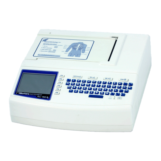
The MORTARA ELI 150 is an advanced interpretive electrocardiograph system utilizing the latest electronic technology and software. The ELI 150 offers 12-lead patient ECG monitoring, a 320 by 240 LCD display. A full function touchpad keyboard, 4-inch thermal writer for printing waveforms and interpretive data, a real-time electronic clock and calendar, an RS-232 level serial communications port, internal power supply, battery, and battery re-charge circuitry and optional internal MODEM. -
Page 74: Eli 250/210 Block Diagram
ELI 150 ELI 150 Block Diagram... -
Page 75: Main System Board
The main system board or motherboard of the ELI 150 contains the digital logic circuitry and the power supply of the ELI 150. The rear section of the motherboard (located at what is the back of the unit when mounted in the chassis) contains the power supply of the unit. -
Page 76: Patient Input
ELI 150 Patient Input Connector: Pin #: Name: Description: Patient Lead Patient Lead Patient Lead Patient Lead Patient Lead SHIELD Isolated Front-End Ground Reserved Reserved Patient Lead Patient Lead Patient Lead Patient Lead Reserved Patient Lead Reserved... - Page 77 Section 5 Specifications...
-
Page 78: Parts List
HOUSING UPPER ELI 150 8347-002-50 HOUSING LOWER ELI 150 8347-003-50 KEYBOARD BEZEL ELI 150 9042-044-01 LABEL AC ON / BATTERY CHARGED ELI 150 9042-045-01 LABEL ELI 1XX SERIES NAMEPLATE 22500-100-60 ELI 150 WRITER ASSEMBLY 4" 25018-035-50 CABLE ASSEMBLY 14 CONDUCTOR... - Page 79 Section 5 The following parts are associated with the GSM version of the ELI 150. QTY Per Item Number Part Number Part Description Unit Cable Assembly ELI 200+ Printhead to PCB (For use in connecting the SIM Simulator board to Remote SIM...
-
Page 81: Troubleshooting And Testing
Section 6 Troubleshooting and Testing Introduction Since repair of the ELI 150 is limited to replacement of subassemblies the troubleshooting guide does not extend to the component level CAUTION: Remove AC power and battery fuse before attempting any disassembly. Removal of the battery fuse will not cause a loss of ECG’s or of the configuration. This information is stored in FLASH memory. - Page 82 ELI 150 Unit turns on, no waveform is displayed but function key options are displayed. Press any key on the keyboard, if no response there is a possible communications problem between front end board and motherboard. 1) Replace cable between front end and motherboard.
-
Page 83: Optional Modem Transmit/Receive Problems
Section 6 RS-232 Transmit/Receive Problems Make sure that the baud rate set in the configuration matches that of the system that is being transmitted to or received from. If the baud rate is set correct there is a problem with either the transmission cable or the RS232 portion of the motherboard and the motherboard should be replaced. -
Page 84: Testing
ELI 150 Testing CAUTION: Dangerous voltages are present on the circuit board of the ELI 150. Caution should be taken when removing or replacing the motherboard. Power Supply Test 1.) Remove battery fuse and AC power from the unit. 2.) Open unit to access the connections to the battery. -
Page 85: Speaker Test
Section 6 Speaker Test 1.) Turn the unit on. 2.) Press the F6, More, key. 3.) Press the number 3 key to select the “Date & Time” option. 4.) Press the following key strokes to access the configuration options: ALT + Shift + C 5.) Page through the configuration to find the Volume option. -
Page 86: Date / Time Test
5.) Press the F5 Save option to save the changes. 6.) Press the F6 Exit option to return to the main menu of the ELI 150. 7.) Observe the time in the lower left corner of the display it should be set to the correct time. - Page 87 Section 6 Description of printout At the top of the writer test print out will be the printable characters of the writer. The next section will have a 200-mm line. This line should be measured with a ruler and will indicate if there is a writer motor problem if the line is too short or too long.
-
Page 88: Adjusting The Writer Cue Sensor
Adjusting the Writer Cue Sensor CAUTION: Dangerous voltages are present on the circuit board of the ELI 150. Caution should be taken when connecting test equipment to the circuit board. Note: This procedure should be performed any time the Cue Sensor or the Motherboard is replaced. -
Page 89: Noise Test
Section 6 Noise Test Perform the noise test using a shorting plug of the following design. Please note that Mortara Instrument does not supply this shorting plug 1.) Turn the unit on with the shorting plug connected to the input connector of the unit. 2.) Increase the gain of the unit to 20mm/mV. -
Page 90: Lead Fail Test
ELI 150 Lead Fail Test Perform the lead fail test as follows: Connect the patient cable to a simulator or a shorting bar. Disconnect one lead at a time from the simulator or shorting bar and verify that the correct lead fail message appears on the LCD while in the Main Menu screen. Only the message for the disconnected lead should appear as shown below. - Page 91 Section 6 stored ECGs will remain in the directory until it becomes full, at this time, the ELI 250/210 will automatically remove a record, based on its size, in order to make room for the new ECG. Only those records that have been marked for deletion will be removed.
-
Page 92: Serial Port Test
ELI 150 The following screen appears during a batch transmission or for a single record transmission: After the transmission of your record(s), the Real-Time ECG View is displayed. Serial Port Test (Direct connect transmission) For a direct connection hookup, connect the ELI 250/210 to another ELI 250/210 with a direct connect serial cable (Mortara P/N: 25000-024). - Page 93 Section 6 Real Time ECG View Application Menu From the Application Menu, simultaneously press ALT+SHIFT+M to access the modem initialization string. The following screens appear: Approximately 30 second delay Select F2 (+GCI=) to populate the prefix “AT+GCI” of the modem command. 6-13...
-
Page 94: Receive Ecgs
ELI 150 TIP: “AT+GCI” will be highlighted – cursor is not present – use keypad to enter country code. Enter your country code as listed below. Select F1 (Send) to change your country code. “Command stored” will be displayed. Select F6 (Exit) to return to the Application Menu. -
Page 95: Wlan Test
Received ECGs will not be viewed or stored. To terminate the receiving mode, press the STOP key. Note: The ELI 150 will receive records from Mortara model cardiographs. The Mortara model cardiographs (ELI 100, ELI 200, Landscape, and Portrait) will not receive the ELI 150 records. -
Page 96: Safety Test
ELI 150 Set the “Default XMT Media” to WLAN and install your network information; the following settings are required in the cardiograph and should be obtained from your local network personnel: Host IP address (network specific) Port #: 5005 SSID:... - Page 97 Section 6 ELI150 TEST DATA RECORD Unit Serial #:______________________________ Device Cleaning Print device configuration (Attach to this report) Power Testing 1. Note Battery Age (If not possible enter N/A) ____/____ (week/year) 2. Off Current ______ uA (<40uA) 3.
-
Page 98: Connectivity Options
The Serial Connectivity option will allow the user to transmit and receive ECG information via the nine pin serial port on the back of the ELI 150. The RS232/Serial Connectivity option is the only option that does not require a modification to the motherboard of the ELI 150 but requires the connectivity option within the ELI 150 software be installed. -
Page 99: Lan Connectivity Option
ELI 150 LAN Connectivity Option The LAN Connectivity option for the ELI 150 is soldered to the motherboard and is not field replaceable. If there is a problem with the LAN option the motherboard will require replacement. -
Page 101: Gsm Modem Connectivity Option
By looking at the motherboard or the GSM modem itself you will not be able to tell which GSM modem is installed. If the motherboard of the ELI 150 must be replaced it must be replaced with the correct type of GSM mode. To ensure that the correct options are installed please make sure that when ordering the board you specify the UNIT serial number. - Page 102 Section 7 The antenna cable, item 52, will need to be removed from the modem of the old motherboard and connected to the modem of the new motherboard. A connection from the GSM modem to the Remote SIM Connector PCM, item 51, board will be required. Take either the existing SIM simulator board, item 50, and the cable, item 49, or the cable assembly supplied with the replacement motherboard and the install it onto the GSM modem as shown.
- Page 103 ELI 150 Use tape to secure the SIM simulator PCB, item 50, to the GSM modem. Install the 4 standoffs, item 55, onto the motherboard. The standoffs will secure the Remote SIM Connector PCB to the motherboard.
- Page 104 Section 7 Install the remaining end of the SIM simulator cable, item 49, by connecting it to the Remote SIM PCB, item 51. Press the Remote SIM PCB, item 51, onto the standoffs making sure that the orientation of the Remote SIM PCB is correct.
Need help?
Do you have a question about the ELI 150 and is the answer not in the manual?
Questions and answers
The machine says that V2 is off when the patient is set up and all leads firmly attached. No indication that there should be an interruption in the signal.