Table of Contents
Advertisement
Advertisement
Table of Contents

Related Manuals for ECS 945GCT-M/1333


Summary of Contents for ECS 945GCT-M/1333
- Page 3 Preface Copyright This publication, including all photographs, illustrations and software, is protected under international copyright laws, with all rights reserved. Neither this manual, nor any of the material contained herein, may be reproduced without written consent of the author. Version 3.0 Disclaimer The information in this document is subject to change without notice.
-
Page 4: Declaration Of Conformity
Declaration of Conformity This device complies with part 15 of the FCC rules. Operation is subject to the following conditions: • This device may not cause harmful interference, and • This device must accept any interference received, including interfer- ence that may cause undesired operation Canadian Department of Communications This class B digital apparatus meets all requirements of the Canadian Interference- causing Equipment Regulations. -
Page 5: Table Of Contents
T T T T T ABLE OF CONTENTS ABLE OF CONTENTS ABLE OF CONTENTS ABLE OF CONTENTS ABLE OF CONTENTS Preface Chapter 1 Introducing the Motherboard Introduction..................1 Feature....................2 Motherboard Components.............4 Chapter 2 7 7 7 7 7 Installing the Motherboard Safety Precautions................7 Choosing a Computer Case............7 Installing the Motherboard in a Case...........7... - Page 6 Integrated Peripherals............35 Power Management Setup............36 PCI/PnP Setup................37 PC Health Status..............38 Frequency/Voltage Control.............39 Load Default settings.............40 Supervisor Password.............40 User Password...............41 Save & Exit Setup..............41 Exit Without Saving..............41 Updating the BIOS..............42 Chapter 4 Using the Motherboard Software About the Software CD-ROM............43 Auto-installing under Windows 2000/XP/Vista......43 Running Setup.................44 Manual Installation................48 Utility Software Reference............48...
-
Page 7: Introducing The Motherboard
Chapter 1 Introducing the Motherboard Introduction Thank you for choosing the 945GCT-M/1333 motherboard. This motherboard is a high performance, enhanced function motherboard designed to support the LGA775 ® ® ® socket Intel Core 2 Duo/Pentium Dual Core/Celeron 4xx series processors for high-end business or personal desktop markets. -
Page 8: Feature
• Supports “Hyper-Threading” technology CPU * Under ECS validation, this motherboard is capable to support FSB 1333 MHz. “Hyper-Threading” technology enables the operating system into thinking it’s hooked up to two processors, allowing two threads to be run in parallel, both on separate “logical”... -
Page 9: Bios Firmware
Onboard LAN (Optional) The onboard LAN controller provides either of the following features: • Integrated Gigabit Ethernet Controller for PCI Express Applications • Integrated 10/100/1000 transceiver • Wake-On-LAN and remote wake-up support • Integrated Fast Ethernet Controller for PCI Express Applications •... -
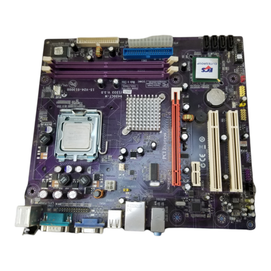
Page 10: Motherboard Components
Motherboard Components Introducing the Motherboard... - Page 11 Table of Motherboard Components LABEL COMPONENTS ® ® LGA775 Socket for Intel Core™ 2 Duo/Pentium 1. CPU Socket ® Dual Core/Celeron 4xx series CPUs 2. CPU_FAN CPU cooling fan connector 3. DIMM1~2 240-pin DDR2 SDRAM slots 4. FDD Floppy Disk Drive connector 5.
- Page 12 Memo Introducing the Motherboard...
-
Page 13: Installing The Motherboard
Chapter 2 Installing the Motherboard Safety Precautions • Follow these safety precautions when installing the motherboard • Wear a grounding strap attached to a grounded device to avoid dam- age from static electricity • Discharge static electricity by touching the metal case of a safely grounded object before working on the motherboard •... -
Page 14: Checking Jumper Settings
Do not over-tighten the screws as this can stress the motherboard. Checking Jumper Settings This section explains how to set jumpers for correct configuration of the motherboard. Setting Jumpers Use the motherboard jumpers to set system configuration options. Jumpers with more than one pin are numbered. -
Page 15: Checking Jumper Settings
Checking Jumper Settings The following illustration shows the location of the motherboard jumpers. Pin 1 is labeled. Jumper Settings Type Jumper Description Setting (default) 1-2: NORMAL 2-3: CLEAR CMOS CLR_CMOS 3-pin Clear CMOS Before clearing the CLR_CMOS CMOS, make sure to turn off the system. -
Page 16: Installing Hardware
Installing Hardware Installing the Processor Caution: When installing a CPU heatsink and cooling fan make sure that you DO NOT scratch the motherboard or any of the surface- mount resistors with the clip of the cooling fan. If the clip of the cooling fan scrapes across the motherboard, you may cause serious damage to the motherboard or its components. -
Page 17: Cpu Installation Procedure
CPU Installation Procedure The following illustration shows CPU installation components. A. Read and follow the instructions shown on the sticker on the CPU cap. B. Unload the cap · Use thumb & forefinger to hold the lifting tab of the cap. ·... -
Page 18: Installing Memory Modules
Installing Memory Modules This motherboard accommodates two memory modules. It can support two 240-pin DDR2 667/533/400. The total memory capacity is 2 GB. DDR2 SDRAM memory module table Memory module Memory Bus DDR2 400 200 MHz DDR2 533 266 MHz DDR2 667 333 MHz You must install at least one module in any of the two slots. - Page 19 Table A: DDR2(memory module) QVL (Qualified Vendor List) The following DDR2 667/533/400 memory modules have been tested and qualified for use with this motherboard. Type Size Vendor Module Name Hynix HYMP532U646-E3-AA 256 MB Nanya NT256T64UH4A0F-5A DDR2 400 Nanya NT512T64U88A0F-5A 512 MB A-DATA M2OHY2F3G3110A1B0Z Elixir...
- Page 20 Please check the table below for the CPU FSB frequency and its corresponding memory support frequency. CPU FSB Frequency Memory Support Frequency DDRII533, DDRII667* 1333 DDRII533, DDRII667 1066 DDRII400, DDRII533, DDRII667 DDRII400, DDRII533 *When you use a FSB1333-CPU on this motherboard, it will run at DDRII500 if you adopt a DDRII533 memory module;...
- Page 21 Table B: DDR2 (memory module) QVL (Qualified Vendor List) The following DDR2 667/533 memory modules have been tested and qualified for use when you use a FSB 1333-CPU on this motherboard. Type Size Vendor Module Name VC256MB533D2 4PB11D9CHM Corsair Aeneon AET94F-370 Eipida E2508AA-DF-E Hynix...
-
Page 22: Expansion Slots
Expansion Slots Installing Add-on Cards The slots on this motherboard are designed to hold expansion cards and connect them to the system bus. Expansion slots are a means of adding or enhancing the motherboard’s features and capabilities. With these efficient facilities, you can increase the motherboard’s capabilities by adding hardware that performs tasks that are not part of the basic system. - Page 23 Follow these instructions to install an add-on card: Remove a blanking plate from the system case corresponding to the slot you are going to use. Install the edge connector of the add-on card into the expansion slot. Ensure that the edge connector is correctly seated in the slot. Secure the metal bracket of the card to the system case with a screw.
-
Page 24: Connecting Optional Devices
Connecting Optional Devices Refer to the following for information on connecting the motherboard’s optional devices: F_AUDIO1: Front Panel Audio header for Azalia This header allows the user to install auxiliary front-oriented microphone and line- out ports for easier access. Signal Name Function Signal Name AUD_MIC... - Page 25 SATA1~4: Serial ATA connectors These connectors are used to support the new Serial ATA devices for the highest data transfer rates (3.0 Gb/s), simpler disk drive cabling and easier PC assembly. It elimi- nates limitations of the current Parallel ATA interface. But maintains register com- patibility and software compatibility with Parallel ATA.
- Page 26 LPT1: Onboard parallel port header This is a header that can be used to connect to the printer, scanner or other devices. Signal Name Signal Name STROBE ERROR INIT SLCTIN Ground Ground Ground Ground Ground Ground BUSK Ground Ground SLCT CD_IN1: Analog Audio Input connector Signal Name Function...
-
Page 27: Installing A Hard Disk Drive/Cd-Rom/Sata Hard Drive
Installing a Hard Disk Drive/CD-ROM/SATA Hard Drive This section describes how to install IDE devices such as a hard disk drive and a CD- ROM drive. About IDE Devices Your motherboard has one IDE channel interface. An IDE ribbon cable supporting two IDE devices is bundled with the motherboard. -
Page 28: Installing A Floppy Diskette Drive
Refer to the illustration below for proper installation: Attach either cable end to the connector on the motherboard. Attach the other cable end to the SATA hard drive. Attach the SATA power cable to the SATA hard drive and connect the other end to the power supply. -
Page 29: Connecting I/O Devices
Connecting I/O Devices The backplane of the motherboard has the following I/O ports: Use the upper PS/2 port to connect a PS/2 pointing PS2 Mouse device. Use the lower PS/2 port to connect a PS/2 keyboard. PS2 Keyboard Use the COM port to connect serial devices such as mice Serial Port or fax/modems. -
Page 30: Connecting Case Components
Connecting Case Components After you have installed the motherboard into a case, you can begin connecting the motherboard components. Refer to the following: Connect the CPU cooling fan cable to CPU_FAN. Connect the system cooling fan connector to SYS_FAN. Connect the case switches and indicator LEDs to the F_PANEL1. Connect the standard power supply connector to ATX1. - Page 31 Connecting 24-pin power cable The ATX1 24-pin connector allows you to connect to ATX v2.x power supply. With ATX v2.x power supply, users please note that when installing 24-pin power cable, the latches of power cable and the ATX1 match perfectly. 24-pin power cable Connecting 4-pin power cable The ATX12V1 power connector is used to provide power to the CPU.
- Page 32 ATX1: ATX 24-pin Power Connector Signal Name Signal Name +3.3V +3.3V +3.3V -12V Ground Ground PS_ON Ground Ground Ground Ground Ground PWRGD +5VSB +12V +12V +3.3V Ground ATX12V1: ATX 12V Power Connector Signal Name Ground Ground +12V +12V Installing the Motherboard...
-
Page 33: Front Panel Header
Front Panel Header The front panel header (F_PANEL1) provides a standard set of switch and LED headers commonly found on ATX or Micro ATX cases. Refer to the table below for information: Signal Function Signal Function HD_LED_P Hard disk LED(+) FP PWR/SLP *MSG LED(+) HD_LED_N Hard disk LED(- ) - Page 34 Memo Installing the Motherboard...
-
Page 35: Using Bios
Chapter 3 Using BIOS About the Setup Utility The computer uses the latest “American Megatrends Inc.” BIOS with support for Windows Plug and Play. The CMOS chip on the motherboard contains the ROM setup instructions for configuring the motherboard BIOS. The BIOS (Basic Input and Output System) Setup Utility displays the system’s configuration status and provides you with options to set system parameters. -
Page 36: Using Bios
Press the delete key to access the BIOS Setup Utility. CMOS Setup Utility -- Copyright (C) 1985-2005, American Megatrends, Inc. Standard CMOS Setup Frequency/Voltage Control Advanced Setup Load Default Settings Advanced Chipset Setup Supervisor Password Integrated Peripherals User Password Power Management Setup Save &... -
Page 37: Standard Cmos Setup
For the purpose of better product maintenance, the manufacture reserves the right to change the BIOS items presented in this manual. The BIOS setup screens shown in this chapter are for reference only and may differ from the actual BIOS. Please visit the manufacture’s website for updated manual. - Page 38 Type (Auto) Use this item to configure the type of the IDE device that you specify. If the feature is enabled, it will enhance hard disk performance by reading or writing more data during each transfer LBA/Large Mode (Auto) Use this item to set the LBA/Large mode to enhance hard disk performance by optimizing the area the hard disk is visited each time.
-
Page 39: Advanced Setup
Advanced Setup This page sets up more advanced information about your system. Handle this page with caution. Any changes can affect the operation of your computer. CMOS Setup Utility - Copyright (C) 1985-2005, American Megatrends, Inc. Advanced Setup Help Item CPU TM function Enabled Max CPUID Value Limit... -
Page 40: Advanced Chipset Setup
Boot Other Device (Enabled) When enabled, the system searches all other possible locations for an operating system if it fails to find one in the devices specified under the First, Second and Third boot devices. High Performance Event Timer (Enabled) This item enables or disables HPET (High Presion Event Timer) support. -
Page 41: Integrated Peripherals
Integrated Peripherals This page sets up some parameters for peripheral devices connected to the system. CMOS Setup Utility - Copyright (C) 1985-2005, American Megatrends, Inc. Integrated Peripherals Onboard IDE Controller Enabled Help Item Onboard SATA Controller Enabled USB Functions Enabled Disable / Enable the Legacy USB Support Enabled... -
Page 42: Power Management Setup
Parallel Port Mode (ECP) Use this item to select the parallel port mode. You can select Normal (Standard Parallel Port), ECP (Extended Capabilities Port), EPP (Enhanced Parallel Port), or BPP (Bi-Directional Parallel Port). ECP Mode DMA Channel (DMA3) Use this item to assign the DMA Channel under ECP Mode function. Parallel Port IRQ (IRQ7) Use this item to assign IRQ to the parallel port. -
Page 43: Pci/Pnp Setup
Wake-Up by PME (Enabled) The system can be turned off with a software command. If you enable this item, the system can automatically resume if there is an incoming call on the PCI Modem or PCI LAN card. You must use an ATX power supply in order to use this feature. Use this item to do wake-up action if inserting the PCI card. -
Page 44: Pc Health Status
Allocate IRQ to PCI VGA (Yes) If this item is enabled, an IRQ will be assigned to the PCI VGA graphics system. You set this value to No to free up an IRQ. Press <Esc> to return to the main menu setting page. PC Health Status On motherboards support hardware monitoring, this item lets you monitor the parameters for critical voltages, temperatures and fan speeds. -
Page 45: Frequency/Voltage Control
SMART Fan Slope PWM value (2 PWM value/°C) This item is used to set the Slope Select PWM of the smart fan. Press <Esc> to return to the PC Health Status page. Shutdown Temperature (Disabled) Enable you to set the maximum temperature the system can reach before powering down. -
Page 46: Load Default Settings
Spread Spectrum (Disabled) If you enable spread spectrum, it can significantly reduce the EMI (Electro-Magnetic Interference) generated by the system. CPU Frequency (Auto) Use this option to adjust CPU frequency. And this item shows only when the FSB reaches 1333 MHz. Press <Esc>... -
Page 47: User Password
User Password This page helps you install or change a password. CMOS Setup Utility - Copyright (C) 1985-2005, American Megatrends, Inc. User Password Help Item Security Settings User Password : Not Installed : Move Enter : Select +/-/: Value F10: Save and Exit F1:General Help F9: Optimized Defaults ESC: Exit... -
Page 48: Updating The Bios
Updating the BIOS You can download and install updated BIOS for this motherboard from the manufacturer’s Web site. New BIOS provides support for new peripherals, improve- ments in performance, or fixes for known bugs. Install new BIOS as follows: Create a bootable system disk. (Refer to Windows online help for information on creating a bootable system disk.) Download the Flash Utility and new BIOS file from the manufacturer’s Web site. -
Page 49: Using The Motherboard Software
Chapter 4 Using the Motherboard Software About the Software CD-ROM The support software CD-ROM that is included in the motherboard package contains all the drivers and utility programs needed to properly run the bundled products. Below you can find a brief description of each software program, and the location for your motherboard version. -
Page 50: Running Setup
Setup Tab Click the Setup button to run the software installation program. Setup Select from the menu which software you want to install. Browse CD The Browse CD button is the standard Windows command that allows you to open Windows Explorer and show the contents of the support CD. - Page 51 Click Next. The following screen appears: Check the box next to the items you want to install. The default options are recommended. Click Next run the Installation Wizard. An item installation screen appears: Follow the instructions on the screen to install the items. 1.
- Page 52 Method 1. Run Reboot Setup Windows Vista will block startup programs by default when installing drivers after the system restart. You must select taskbar icon Run Blocked Program and run Reboot Setup to install the next driver, until you finish all drivers installation. Method 2.
- Page 53 Select Classic View. Set User Account. Select Turn User Account Control on or off and press Continue. Using the Motherboard Software...
-
Page 54: Manual Installation
Disable User Account Control (UAC) to help protect your computer item and press OK, then press Restart Now. Then you can restart your computer and continue to install drivers without running blocked programs. Manual Installation Insert the CD in the CD-ROM drive and locate the PATH.DOC file in the root directory.
Need help?
Do you have a question about the 945GCT-M/1333 and is the answer not in the manual?
Questions and answers