Table of Contents
Advertisement
Advertisement
Table of Contents

Related Manuals for ECS 945GCD-CI


Summary of Contents for ECS 945GCD-CI
- Page 3 Preface Copyright This publication, including all photographs, illustrations and software, is protected under international copyright laws, with all rights reserved. Neither this manual, nor any of the material contained herein, may be reproduced without written consent of the author. Version 1.0 Disclaimer The information in this document is subject to change without notice.
-
Page 4: Declaration Of Conformity
Declaration of Conformity This device complies with part 15 of the FCC rules. Operation is subject to the following conditions: • This device may not cause harmful interference, and • This device must accept any interference received, including interfer- ence that may cause undesired operation Canadian Department of Communications This class B digital apparatus meets all requirements of the Canadian Interference- causing Equipment Regulations. -
Page 5: Table Of Contents
T T T T T ABLE OF CONTENTS ABLE OF CONTENTS ABLE OF CONTENTS ABLE OF CONTENTS ABLE OF CONTENTS Preface Chapter 1 Introducing the Motherboard Introduction..................1 Feature....................2 Motherboard Components.............4 Chapter 2 7 7 7 7 7 Installing the Motherboard Safety Precautions................7 Choosing a Computer Case............7 Installing the Motherboard in a Case..........7... - Page 6 Integrated Peripherals............30 Power Management Setup..........32 PCI/PnP Setup..............33 PC Health Status...............34 Frequency/Voltage Control..........35 Load Default Settings............36 Supervisor Password............36 User Password..............37 Save & Exit Setup..............37 Exit Without Saving............37 Chapter 4 39 39 Using the Motherboard Software About the Software CD-ROM............39 Auto-installing under Windows Vista........39 Running Setup..............40 Manual Installation................44 Utility Software Reference............44...
-
Page 7: Introducing The Motherboard
Chapter 1 Introducing the Motherboard Introduction Thank you for choosing 945GCD-CI motherboard of great performance and with ® enhanced function. This motherboard has onboard Intel Atom CPU with a Mini- ITX form factor of 170 x 170 mm. The motherboard incorporates the 945GC Northbridge (NB) and ICH7 Southbridge (SB) chipsets. -
Page 8: Feature
Feature Processor ® This motherboard uses onboard Intel Atom CPU that carries the following features: • Onboard Intel ® Atom single core, 1.60GHz CPU speed with 512KB cache • Supports a system bus (FSB) of 533 MHz • Supports “Hyper-Threading” technology CPU “Hyper-Threading”... -
Page 9: Onboard Lan
Onboard LAN The onboard LAN controller provides either of the following features: • Supports PCI Express • Integrated 10/100/1000 transceiver • Wake-on-LAN and remote wake-up support • Integrated 10/100 transceiver • Wake-on-LAN and remote wake-up support • Fully complies with IEEE802.3, IEEE802.3u Expansion Options The motherboard comes with the following expansion options: •... -
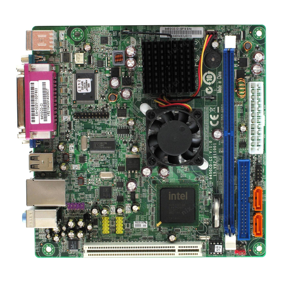
Page 10: Motherboard Components
Motherboard Components Introducing the Motherboard... - Page 11 Table of Motherboard Components LABEL COMPONENTS 1. MCH_FAN Northbridge cooling fan connector 2. DIMM1 240-pin DDR2 SDRAM slots 3. ATX1 Standard 24-pin ATX power connector 4. IDE Primary IDE connector 5. PANEL1 Front panel switch/LED header 6. SATA1~2 Serial ATA connectors 7.
- Page 12 Memo Introducing the Motherboard...
-
Page 13: Installing The Motherboard
Chapter 2 Installing the Motherboard Safety Precautions • Follow these safety precautions when installing the motherboard • Wear a grounding strap attached to a grounded device to avoid dam- age from static electricity • Discharge static electricity by touching the metal case of a safely grounded object before working on the motherboard •... -
Page 14: Checking Jumper Settings
Do not over-tighten the screws as this can stress the motherboard. Checking Jumper Settings This section explains how to set jumpers for correct configuration of the motherboard. Setting Jumpers Use the motherboard jumpers to set system configuration options. Jumpers with more than one pin are numbered. -
Page 15: Checking Jumper Settings
Checking Jumper Settings The following illustration shows the location of the motherboard jumpers. Pin 1 is labeled. Jumper Settings Jumper Type Description Setting (default) 1-2: NORMAL 2-3: CLEAR CMOS CLR_CMOS1 3-pin CLEAR CMOS Before clearing the CMOS, make sure to CLR_CMOS1 turn the system off. -
Page 16: Installing Hardware
Installing Hardware Installing Memory Modules This motherboard accommodates one memory module. It can support one 240-pin DDR2 533. The total memory capacity is 2 GB. DDR2 SDRAM memory module table Memory module Memory Bus DDR2 533 266 MHz Do not remove any memory module from its antistatic packaging until you are ready to install it on the motherboard. - Page 17 Table A: DDR2 (memory module) QVL (Qualified Vendor List) The following DDR2 800/667/533 memory modules have been tested and qualified for use with this motherboard. Type Size Vendor Module Name Kingston Hynix HY5PS12821 5PB32 D9DCN Ramaxel 512 MB 6AD11 D9GCT K4T51083QF-ZCD5 Samsung DDR2 533...
-
Page 18: Expansion Slots
Expansion Slots Installing Add-on Cards The slots on this motherboard are designed to hold expansion cards and connect them to the system bus. Expansion slots are a means of adding or enhancing the motherboard’s features and capabilities. With these efficient facilities, you can in- crease the motherboard’s capabilities by adding hardware that performs tasks that are not part of the basic system. - Page 19 Follow these instructions to install an add-on card: Remove a blanking plate from the system case corresponding to the slot you are going to use. Install the edge connector of the add-on card into the expansion slot. Ensure that the edge connector is correctly seated in the slot. Secure the metal bracket of the card to the system case with a screw.
-
Page 20: Connecting Optional Devices
Connecting Optional Devices Refer to the following for information on connecting the motherboard’s optional devices: F_AUDIO1: Front Panel Audio header This header allows the user to install auxiliary front-oriented microphone and line- out ports for easier access. Signal Name Signal Name PORT 1L AUD_GND PORT 1R... - Page 21 USB2~3: Front Panel USB headers The motherboard has four USB ports installed on the rear edge I/O port array. Additionally, some computer cases have USB ports at the front of the case. If you have this kind of case, use auxiliary USB connector to connect the front-mounted ports to the motherboard.
-
Page 22: Installing A Hard Disk Drive/Cd-Rom/Sata Hard Drive
Installing a Hard Disk Drive/CD-ROM/SATA Hard Drive This section describes how to install IDE devices such as a hard disk drive and a CD- ROM drive. About IDE Devices Your motherboard has one IDE channel interface. An IDE ribbon cable supporting two IDE devices is bundled with the motherboard. - Page 23 Refer to the illustration below for proper installation: Attach either cable end to the connector on the motherboard. Attach the other cable end to the SATA hard drive. Attach the SATA power cable to the SATA hard drive and connect the other end to the power supply.
-
Page 24: Connecting I/O Devices
Connecting I/O Devices The backplane of the motherboard has the following I/O ports: PS2 Mouse Use the upper PS/2 port to connect a PS/2 pointing device. PS2 Keyboard Use the lower PS/2 port to connect a PS/2 keyboard. Parallel Port (LPT1) Use LPT1 to connect printers or other parallel communi- cations devices. -
Page 25: Connecting Case Components
Connecting Case Components After you have installed the motherboard into a case, you can begin connecting the motherboard components. Refer to the following: Connect the system cooling fan connector to SYS_FAN. Connect the Northbridge cooling fan connector to MCH_FAN. Connect the case switches and indicator LEDs to the PANEL1. Connect the standard power supply connector to ATX1. - Page 26 SYS_FAN/MCH_FAN: FAN Power Connectors Signal Name Function System Ground Power +12V +12V Sense Sensor ATX1: ATX 24-pin Power Connector Signal Name Signal Name +3.3V +3.3V +3.3V -12V Ground Ground PS_ON Ground Ground Ground Ground Ground PWRGD +5VSB +12V +12V +3.3V Ground Installing the Motherboard...
-
Page 27: Front Panel Header
Front Panel Header The front panel header (PANEL1) provides a standard set of switch and LED headers commonly found on ATX or Micro ATX cases. Refer to the table below for informa- tion: Signal Function Signal Function HD_LED_P Hard disk LED(+) 2 FP PWR/SLP *MSG LED(+) HD_LED_N Hard disk LED(- ) FP PWR/SLP *MSG LED(-) - Page 28 Memo Installing the Motherboard...
-
Page 29: Using Bios
Chapter 3 Using BIOS About the Setup Utility The computer uses the latest “American Megatrends Inc. ” BIOS with support for Windows Plug and Play. The CMOS chip on the motherboard contains the ROM setup instructions for configuring the motherboard BIOS. The BIOS (Basic Input and Output System) Setup Utility displays the system ’... -
Page 30: Bios Navigation Keys
Press DEL to enter SETUP Press the DEL key to access the BIOS Setup Utility. CMOS Setup Utility -- Copyright (C) 1985-2005, American Megatrends, Inc. Standard CMOS Setup PC Health Status Advanced Setup Frequency/Voltage Control Advanced Chipset Setup Load Default Settings Integrated Peripherals Supervisor Password Power Management Setup... -
Page 31: Updating The Bios
Updating the BIOS You can download and install updated BIOS for this motherboard from the manufacturer’s Web site. New BIOS provides support for new peripherals, improve- ments in performance, or fixes for known bugs. Install new BIOS as follows: Create a bootable system disk. (Refer to Windows online help for information on creating a bootable system disk.) Download the Flash Utility and new BIOS file from the manufacturer’s Web site. -
Page 32: Standard Cmos Setup
Standard CMOS Setup This option displays basic information about your system. CMOS Setup Utility -- Copyright (C) 1985-2005, American Megatrends, Inc. Standard CMOS Setup Help Item Date Wed 07/23/2008 Time 05 : 33 : 10 Use [ENTER], [TAB] SATA Channel 1 Hard Disk or [SHIFT-TAB] to SATA Channel 2... - Page 33 Type (Auto) Use this item to configure the type of the IDE device that you specify. If the feature is enabled, it will enhance hard disk performance by reading or writing more data during each transfer LBA/Large Mode (Auto) Use this item to set the LAB/Large mode to enhance hard disk performance by optimizing the area the hard disk is visited each time.
-
Page 34: Advanced Setup
Advanced Setup This page sets up more advanced information about your system. Handle this page with caution. Any changes can affect the operation of your computer. CMOS Setup Utility - Copyright (C) 1985-2005, American Megatrends, Inc. Advanced Setup Help Item TM Status TM1/TM2 Limit CPUID MaxVal... -
Page 35: Advanced Chipset Setup
Hard Disk Drives (Press Enter) Scroll to this item and press <Enter> to view the following screen: CMOS Setup Utility - Copyright (C) 1985-2005, American Megatrends, Inc. Hard Disk Drives Help Item Hard Disk Drives 1st Drive WDC WD1600JS-22NCB1 Specifies the boot sequence from the available devices. -
Page 36: Integrated Peripherals
Configure DRAM Timing by SPD (Enabled) When this item is set to enable, the DDR timing is configured using SPD. SPD (Serial Presence Detect) is located on the memory modules, BIOS reads information coded in SPD during system boot up. DVMT Mode Select (DVMT Mode) DVMT is Dynamic Video Memory Technology. - Page 37 Serial Port1 Address (3F8/IRQ4) Use this item to enable or disable the onboard COM1 serial port, and to assign a port address. Parallel Port Address (378) Use this item to enable or disable the onboard Parallel port, and to assign a port address.
-
Page 38: Power Management Setup
Power Management Setup This page sets up some parameters for system power management operation. CMOS Setup Utility - Copyright (C) 1985-2005, American Megatrends, Inc. Power Management Setup Help Item ACPI Suspend Type S3 (STR) Soft-off by PWR-BTTN Instant Off PWRON After PWR-Fail Power Off Select the ACPI Resume By RING... -
Page 39: Pci/Pnp Setup
Resume on RTC Alarm (Disabled) The system can be turned off with a software command. If you enable this item, the system can automatically resume at a fixed time based on the system RTC (realtime clock). Use the items below this one to set the date and time of the wake-up alarm. You must use an ATX power supply in order to use this feature. -
Page 40: Pc Health Status
PC Health Status On motherboards support hardware monitoring, this item lets you monitor the parameters for critical voltages, temperatures and fan speeds. CMOS Setup Utility - Copyright (C) 1985-2005, American Megatrends, Inc. PC Health Status Help Item System Temperature : 29°C/84°F CPU Temperature : 25°C/77°F SYS FAN Speed... -
Page 41: Frequency/Voltage Control
Frequency/Voltage Control This page enables you to set the clock speed and system bus for your system. The clock speed and system bus are determined by the kind of processor you have in- stalled in your system. CMOS Setup Utility - Copyright (C) 1985-2005, American Megatrends, Inc. Frequency/Voltage Control Help item Configure advanced CPU settings... -
Page 42: Load Default Settings
Load Default Settings This option opens a dialog box that lets you install stability-oriendted defaults for all appropriate items in the Setup Utility. Select [OK] and then press <Enter> to install the defaults. Select [Cancel] and then press <Enter> to not install the defaults. Supervisor Password This page helps you install or change a password. -
Page 43: User Password
User Password This page helps you install or change a password. CMOS Setup Utility - Copyright (C) 1985-2005, American Megatrends, Inc. User Password User Password : Not Installed Help Item Install or Change the Change User Password Press Enter password. : Move Enter : Select +/-/: Value... - Page 44 Memo Using BIOS...
-
Page 45: Using The Motherboard Software
Chapter 4 Using the Motherboard Software About the Software CD-ROM The support software CD-ROM that is included in the motherboard package contains all the drivers and utility programs needed to properly run the bundled products. Below you can find a brief description of each software program, and the location for your motherboard version. -
Page 46: Running Setup
Setup Tab Setup Click the Setup button to run the software installation program. Select from the menu which software you want to install. Browse CD The Browse CD button is the standard Windows command that al- lows you to open Windows Explorer and show the contents of the support CD. - Page 47 Click Next. The following screen appears: Check the box next to the items you want to install. The default options are recom- mended. Click Next run the Installation Wizard. An item installation screen appears: Follow the instructions on the screen to install the items. 1.
- Page 48 Method 1. Run Reboot Setup Windows Vista will block startup programs by default when installing drivers after the system restart. You must select taskbar icon Run Blocked Program and run Reboot Setup to install the next driver, until you finish all drivers installation. Method 2.
- Page 49 Select Classic View. Set User Account. Select Turn User Account Control on or off and press Continue. Using the Motherboard Software...
-
Page 50: Manual Installation
Disable User Account Control (UAC) to help protect your computer item and press OK, then press Restart Now. Then you can restart your computer and continue to install drivers without running blocked programs. Manual Installation Insert the CD in the CD-ROM drive and locate the PATH.DOC file in the root directory.
Need help?
Do you have a question about the 945GCD-CI and is the answer not in the manual?
Questions and answers