Table of Contents
Advertisement
Advertisement
Table of Contents

Subscribe to Our Youtube Channel
Related Manuals for ECS 945P-A


Summary of Contents for ECS 945P-A
- Page 3 Preface Copyright This publication, including all photographs, illustrations and software, is protected under international copyright laws, with all rights reserved. Neither this manual, nor any of the material contained herein, may be reproduced without written consent of the author. Version 1.0a Disclaimer The information in this document is subject to change without notice.
-
Page 4: Declaration Of Conformity
Declaration of Conformity This device complies with part 15 of the FCC rules. Operation is subject to the following conditions: • This device may not cause harmful interference, and • This device must accept any interference received, including interference that may cause undesired operation Canadian Department of Communications This class B digital apparatus meets all requirements of the Canadian Interference-causing Equipment Regulations. -
Page 5: Table Of Contents
T T T T T ABLE OF CONTENTS ABLE OF CONTENTS ABLE OF CONTENTS ABLE OF CONTENTS ABLE OF CONTENTS Preface Chapter 1 Introducing the Motherboard Introduction....................1 Feature......................2 Motherboard Components................4 7 7 7 7 7 Chapter 2 Installing the Motherboard Safety Precautions..................7 Choosing a Computer Case...............7 Installing the Motherboard in a Case............7... - Page 6 Power Management Features............35 Hardware Health Features............37 BIOS Security Features..............39 Load Optimal Defaults..............40 Load Performance Defaults............40 Save Changes and Exit..............40 Discard Changes and Exit............40 Chapter 4 41 41 41 41 41 Using the Motherboard Software About the Software CD-ROM..............41 Auto-installing under Windows 2000/XP..........41 Running Setup................42 Manual Installation..................44 Utility Software Reference...............44...
-
Page 7: Introducing The Motherboard
SATA II compliant, supporting four SATA ports with maximum transfer rate up to 3.0 Gb/s each. The 945P-A motherboard is equipped with advanced full set of I/O ports in the rear panel, including PS/2 mouse and keyboard connectors, COM1, LPT1, four USB ports, one op- tional LAN port, and audio jacks for microphone, line-in and 8-ch line out. -
Page 8: Feature
Feature Processor The 945P-A uses an LGA775 type of Pentium 4/Pentium D that carries the following features: • Accommodates Intel Pentium 4/Pentium D processors • Supports a system bus (FSB) of 1066/800/533MHz • Supports “Hyper-Threading” technology CPU “Hyper-Threading” technology enables the operating system into thinking it’s hooked up to two processors, allowing two threads to be run in parallel, both on separate “logical”... - Page 9 One 40-pin IDE low profile connector that support two IDE devices • One floppy disk drive connector • Four 7-pin SATA connectors The 945P-A motherboard supports UltraDMA bus mastering with transfer rates of 100/ 66 MB/s. Integrated I/O The motherboard has a full set of I/O ports and connectors: •...
-
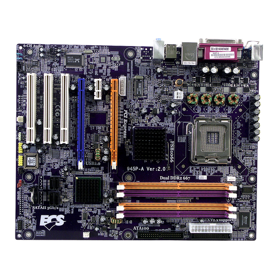
Page 10: Motherboard Components
Motherboard Components Introducing the Motherboard... - Page 11 Table of Motherboard Components LABEL COMPONENT 1 CPU Socket LGA775 socket for Pentium 4/D CPUs 2 CPUFAN1 CPU cooling fan connector 3 DIMM1~4 240-pin DDR2 SDRAM slots 4 ATX1 Standard 24-pin ATX power connector 5 FDD1 Floppy diskette drive connector 6 IDE1 Primary IDE channel 7 SYSFAN3...
- Page 12 Memo Introducing the Motherboard...
-
Page 13: Installing The Motherboard
Chapter 2 Installing the Motherboard Safety Precautions • Follow these safety precautions when installing the motherboard • Wear a grounding strap attached to a grounded device to avoid damage from static electricity • Discharge static electricity by touching the metal case of a safely grounded object before working on the motherboard •... -
Page 14: Checking Jumper Settings
Do not over-tighten the screws as this can stress the motherboard. Checking Jumper Settings This section explains how to set jumpers for correct configuration of the motherboard. Setting Jumpers Use the motherboard jumpers to set system configuration options. Jumpers with more than one pin are numbered. -
Page 15: Checking Jumper Settings
Checking Jumper Settings The following illustration shows the location of the motherboard jumpers. Pin 1 is labeled. Jumper Settings Type Jumper Description Setting (default) 1-2: CLEAR CMOS 3-pin CLEAR CMOS 2-3: NORMAL Before clearing the CMOS, make sure to turn off the system. To avoid the system unstability after clearing CMOS, we recommend users to enter the main BIOS setting page to “Load Optimal De- faults”... -
Page 16: Connecting Case Components
Connecting Case Components After you have installed the motherboard into a case, you can begin con- necting the motherboard components. Refer to the following: Connect the CPU cooling fan cable to CPUFAN1. Connect the system cooling fan connectors to SYSFAN2/3. Connect the connector for graphics interface to ATX4P1. -
Page 17: Atx 24-Pin Power Connector
CPUFAN1: CPU Cooling FAN Power Connector Signal Name Function System Ground Power +12V +12V Sense Sensor CPU FAN control Users please note that the fan connector supports the CPU cooling fan of 1.1A~2.2A (26.4W max.) at +12V. SYSFAN2/3: System Cooling FAN Power Connectors Signal Name Function System Ground... -
Page 18: Front Panel Connector
SPK1: Internal speaker Signal Name Signal Front Panel Connector The front panel connector (PANEL1) provides a standard set of switch and LED connec- tors commonly found on ATX or micro-ATX cases. Refer to the table below for informa- tion: Signal Function Signal Function... -
Page 19: Installing Hardware
Installing Hardware Installing the Processor Caution: When installing a CPU heatsink and cooling fan make sure that you DO NOT scratch the motherboard or any of the surface-mount resistors with the clip of the cooling fan. If the clip of the cooling fan scrapes across the motherboard, you may cause serious damage to the motherboard or its components. -
Page 20: Cpu Installation Procedure
CPU Installation Procedure The following illustration shows CPU installation components. A. Unload the cap · Use thumb & forefinger to hold the lifting tab of the cap. · Lift the cap up and remove the cap completely from the socket. B. -
Page 21: Installing Memory Modules
Installing Memory Modules This motherboard accomodates four memory modules. It can support four 240-pin 1.8V DDR2 667/533/400 DDR SDRAM. The total memory capacity is 4 GB. DDR2 SDRAM memory module table Memory module Memory Bus CPU FSB 533/800MHz DDR2 400 200MHz 533/800/1066MHz DDR2 533... - Page 22 Table A: DDR2 QVL (Qualified Vender List) The following DDR2 memory modules have been tested and qualified for use with this motherboard. Type Size Vendor Model Name Micron MT8HTF3264AG-40EB3 CL3 SS 256MB Hynix HYMP532U646-E3 AA Nanya NT256T64UH4A0F-5A CL3 DDR2 400 Hynix HYMP564U648-E3 AA 512MB...
-
Page 23: Installing A Hard Disk Drive/Cd-Rom/Sata Hard Drive
Installing a Hard Dish Drive/CD-ROM/SATA Hard Drive This section describes how to install IDE devices such as a hard disk drive and a CD-ROM drive. About IDE Devices Your motherboard has one IDE channel interface. An IDE ribbon cable supporting two IDE devices is bundled with the motherboard. -
Page 24: Installing A Floppy Diskette Drive
Refer to the illustration below for proper installation: Attach either cable end to the connector on the motherboard. Attach the other cable end to the SATA hard drive. Attach the SATA power cable to the SATA hard drive and connect the other end to the power supply. -
Page 25: Installing Add-On Cards
Installing Add-on Cards The slots on this motherboard are designed to hold expansion cards and connect them to the system bus. Expansion slots are a means of adding or enhancing the motherboard’s features and capabilities. With these efficient facilities, you can increase the motherboard’s capabili- ties by adding hardware that performs tasks that are not part of the basic system. - Page 26 Follow these instructions to install add-on cards: 1. Open the chassis and then remove the slot bracket from the case where you will be installing the expansion cards. 2. Install your graphics card in the proper slot by pressing the card firmly into the slot.
-
Page 27: Connecting Optional Devices
Connecting Optional Devices Refer to the following for information on connecting the motherboard’s optional devices: AUDIO1: Front Panel Audio header This header allows the user to install auxiliary front-oriented microphone and line-out ports for easier access. Signal Name Signal Name Function AUD_MIC Front Panel Microphone input signal... - Page 28 USB1/2: Front Panel USB header The motherboard has four USB ports installed on the rear edge I/O port array. Additionally, some computer cases have USB ports at the front of the case. If you have this kind of case, use auxiliary USB connector to connect the front-mounted ports to the motherboard. Signal Name Function USBPWR...
-
Page 29: Connecting I/O Devices
Connecting I/O Devices The backplane of the motherboard has the following I/O ports: PS2 Mouse Use the upper PS/2 port to connect a PS/2 pointing device. PS2 Keyboard Use the lower PS/2 port to connect a PS/2 keyboard. Parallel Port (LPT1) Use LPT1 to connect printers or other parallel communications devices. - Page 30 Memo Installing the Motherboard...
-
Page 31: Using Bios
Chapter 3 Using BIOS About the Setup Utility The computer uses the latest American Megatrends BIOS with support for Windows Plug and Play. The CMOS chip on the motherboard contains the ROM setup instructions for configuring the motherboard BIOS. The BIOS (Basic Input and Output System) Setup Utility displays the system’s configura- tion status and provides you with options to set system parameters. -
Page 32: Bios Navigation Keys
Press DEL/F1 to enter SETUP Press the delete key or F1 to access the BIOS Setup Utility. CMOS Setup Utility - Copyright (c) 1985-2004, American Megatrends, Inc. Standard BIOS Features BIOS Security Features Boot Configuration Features Load Optimal Defaults Advanced BIOS Features Load Best Performance Settings Advanced Chipset Features Save Changes and Exit... -
Page 33: Updating The Bios
Updating the BIOS You can download and install updated BIOS for this motherboard from the manufacturer’s Web site. New BIOS provides support for new peripherals, improvements in performance, or fixes for known bugs. Install new BIOS as follows: If your motherboard has a BIOS protection jumper, change the setting to allow BIOS flashing. -
Page 34: Standard Bios Features
Standard BIOS Features This option displays basic information about your system. CMOS Setup Utility - Copyright (c) 1985-2004, American Megatrends, Inc. Standard BIOS Features Help Item System Overview AMIBIOS Use [ENTER], [TAB] Version : 08.00.12 or [SHIFT-TAB] TO Build Date : 03/23/05 select a field. - Page 35 Hard Disk (Press Enter) Scroll to this item and press <Enter> to view the following screen: CMOS Setup Utility - Copyright (c) 1985-2004, American Megatrends, Inc. Hard Disk Drives Help Item Hard Disk Drives 1st Drive [HDD:SM-QUANTUM FIR] Specifies the boot sequence from the available devices.
-
Page 36: Advanced Bios Features
Quick Boot (Enabled) If you enable this item, the system starts up more quickly be elimination some of the power on test routines. Boot Up NumLock (On) This item defines if the keyboard Num Lock key is active when your system is started. Press <Esc>... - Page 37 Ratio Status/Ratio Actual Value These items show the Locked ratio status and the actual ratio of the CPU installed in your system. Ratio CMOS Setting (15) This item sets the ratio between CPU Core Clock and the FSB Frequency. Users please not that if a invalid ratio has been entered to this field, BIOS will restore it to previous state.
- Page 38 IDE Configuration (Press Enter) Scroll to this item and press <Enter> to view the following screen: CMOS Setup Utility - Copyright (c) 1985-2004, American Megatrends, Inc. IDE Configuration IDE Configuration Help Item ATA/IDE Configuration [Compatible] Options Legacy IDE Channels [SATA Pri, PATA Sec] Disabled Primary IDE Master [Not Detected]...
-
Page 39: Advanced Chipset Features
SuperIO Configuration (Press Enter) Scroll to this item and press <Enter> to view the following screen: CMOS Setup Utility - Copyright (c) 1985-2004, American Megatrends, Inc. SuperIO Configuration IDE Configuration Help Item OnBoard Floppy Controller [Enabled] Allows BIOS to Serial Port1 Address [3F8/IRQ4] Enable or Disable Serial Port2 Address... - Page 40 Voltage Adjustment Scroll to this item and press <Enter> to view the following screen: CMOS Setup Utility - Copyright (c) 1985-2004, American Megatrends, Inc. Voltage Adjustment Help Item CPU Vcore Voltage [Auto] Options 1.8V of DDR2 [NORMAL] Auto VDDQ [NORMAL] 1.6000V 1.5875V 1.5750V...
-
Page 41: Power Management Features
Boots Graphic Adapter Priori (PEG/PCI) This item allows you to choose which graphics controller to use as the primary boot device. Auto Detect PCI Clk (Enabled) This item allows you to enable or disable the function of detecting the PCI clock automatically. Spread Spectrum (Enabled) If you enable this function, it can significantly reduce the EMI (Electro-Magnetic Interference) generated by the system. - Page 42 Suspend Time Out (Disabled) This sets the timeout for Suspend mode in minutes. If the time selected passes without any system activity, the computer will enter power-saving Suspend mode. Power Button Mode (On/Off) This item lets you install a software power down controlled by the normal power button on your system.
-
Page 43: Hardware Health Features
Hardware Health Features This option displays basic information about your system. CMOS Setup Utility - Copyright (c) 1985-2004, American Megatrends, Inc. Hardware Health Features Help Item Hardware Healthy Configure SMART FAN Control [Enabled] SMART CPU Temperature [70] °] CPU Tolerance Temperature StartUp Duty-Cycle [128] SMART SYS Temperature... - Page 44 System Component Characteristics These fields provide you with information about the systems current operating status. You cannot make changes to these fields. • VCCP • VDDQ • Fan1 Speed • Fan2 Speed • VCCP • VDDQ • +12V • AVCC •...
-
Page 45: Bios Security Features
BIOS Security Features This option displays basic information about your system. CMOS Setup Utility - Copyright (c) 1985-2004, American Megatrends, Inc. BIOS Security Features Security Settings Help Item Supervisor Password : Not Installed Install or Change User Password : Not Installed the password. -
Page 46: Load Optimal Defaults
Load Optimal Defaults This option opens a dialog box that lets you install optimized defaults for all appropriate items in the Setup Utility. Press <Y> and then <Enter> to install the defaults. Press <N> and then <Enter> to not install the defaults. The optimized defaults place de- mands on the system that may be greater than the performance level of the components, such as the CPU and the memory. -
Page 47: Using The Motherboard Software
Chapter 4 Using the Motherboard Software About the Software CD-ROM The support software CD-ROM that is included in the motherboard package contains all the drivers and utility programs needed to properly run the bundled products. Below you can find a brief description of each software program, and the location for your motherboard version. -
Page 48: Running Setup
Setup Tab Setup Click the Setup button to run the software installation program. Select from the menu which software you want to install. Browse CD The Browse CD button is the standard Windows command that allows you to open Windows Explorer and show the contents of the support Before installing the software from Windows Explorer, look for a file named README.TXT, INSTALL.TXT or something similar. - Page 49 Click Next. The following screen appears: Check the box next to the items you want to install. The default options are recommended. Click Next run the Installation Wizard. An item installation screen appears: Follow the instructions on the screen to install the items. Drivers and software are automatically installed in sequence.
-
Page 50: Manual Installation
Manual Installation Insert the CD in the CD-ROM drive and locate the PATH.DOC file in the root directory. This file contains the information needed to locate the drivers for your motherboard. Look for the chipset and motherboard model; then browse to the directory and path to begin installing the drivers. - Page 51 Caractéristiques Processeur La 945P-A utilise un type LGA775 de Pentium 4/Pentium D présentant les fonctionnalités suivantes: • Peut recevoir les processeurs Intel Pentium 4/Pentium D • Support un bus système (FSB) de 1066/800/533 MHz • Supporte le CPU de technologie “Hyper-Threading”...
- Page 52 Une interface lecteur de disquettes • Quatre connecteurs SATA à 7 broches La 945P-A carte mère prenant en charge la maîtrise de bus UltraDMA avec vitesses de transfert de 100/66 Mo/s. E/S intégrées La carte mère comporte un ensemble complet de connecteurs et de ports E/S : •...
- Page 53 Features Prozessor Der 945P-A benutzt einen Pentium 4/Pentium D des Typs LGA775 und besitzt folgende Eigenschaften: • Nimmt Intel Pentium 4/ Pentium D Prozessoren auf • Unterstützt einen Systembus (FSB) mit 1066/800/533 MHz. • Unterstützt CPU mit “Hyper-Threading”-Technologie. “Hyper-Threading”-Technologie läßt das Betriebssystem glauben, es sei an zwei Prozessoren angeschlossen, was zwei parallele Threads auf separaten ‘logischen’...
- Page 54 Einen 40-Pin IDE low profile-Stecker, die zwei IDE-Kanäle unterstützen • Ein Diskettenlaufwerkanschluss • Vier 7-Pin SATA Anschlüsse Die 945P-A-Motherboard unterstützt UltraDMA Bus Mastering mit einer Übertragungsrate von 100/66 MB/Sek. Integrierte I/O-Schnittstellen Das Motherboard verfügt über einen kompletten Satz von I/O-Schnittstellen und Anschlüssen: •...
- Page 55 Caratteristiche Processore Il 945P-A sfrutta un Pentium 4/Pentium D di tipo LGA775 che dispone delle seguenti caratteristiche: • Compatibile con processori Intel Pentium 4/Pentium D • Supporta un bus di sistema (FSB) fino a 1066/800/533 Mhz • Supporta CPU con tecnologia “Hyper Threading”...
- Page 56 Un’interfaccia per unità disco floppy • Quattro connettori SATA a 7 pin. La scheda madre 945P-A supporta bus master UltraDMA con tasso di trasferimento di 100/66 MB/s. I/O integrati La scheda madre è dotata di un set completo di connettori e porte I/O: •...
- Page 57 Características Procesador La 945P-A usa un tipo LGA775 de Pentium 4/Pentium D que lleva las sigtes. características:: • Acomoda procesadores Intel Pentium 4/Pentium D • Soporta un sistema de bus (FSB) de 1066/800/533 MHz • Soporta CPU de tecnología “Hyper-Threading”...
- Page 58 Una interfaz para unidad de disquete • Cuatro conectores 7-pin SATA La placa principal 945P-A soporta el mastering de bus UltraDMA con índices de transferencia de 100/66 MB/s. I/O integrado La placa base tiene un conjunto completo de puertos I/O y conectores: •...
- Page 59 Características Processador O 945P-A usa um tipo LGA775 de Pentium 4/Pentium D que possui as seguintes características: • Acomoda processadores Intel Pentium 4/Pentium D • Suporta um bus sistema (FSB) de 1066/800/533 MHz • Suporta CPU de tecnologia “Hyper-Threading” A tecnologia “Hyper-Threading” permite que o sistema operativo “pense” que está ligado a dois processadores, permitindo que sejam executados dois threads em paralelo, ambos em processadores “lógicos”...
- Page 60 Uma interface para unidade de disquete • Quatro conectores SATA de 7 pinos A motherboard 945P-A suporta um domínio bus UltraDMA bus com taxas de Transferência de 100/66 MB/s. I/O Integrado A motherboard possui um conjunto completo de portas I/O e conectores: •...
- Page 61 機能 プロセッサ 945P-AはLGA775タイプのPentium 4/Pentium Dに対応したもので、その特徴は次 の通り: • Intel Pentium 4/Pentium D プロセッサが搭載可能 • 1066/800/533MHzのシステムバス(FSB)をサポート • “ハイパースレッド技術対応のCPUを取り付け可能 ハイパースレッド(HT) 技術というのは、オペレーションシステムに2つのプロセッサが存在すると認 識させることで、実際には2つのスレッドを1つのプロセッサで同時に執行させ、平行利用を可能とす る技術です。 チップセット 945P Northbridge (NB)とICH7 Southbridge (SB)チップセットは、実証された信頼性 と性能を持つ革新的で拡張性のあるアーキテクチャに基づいています。 945P (NB) • 32ビットホストバスアドレシング機能対応、これでCPUが4 GBの メモリアドレス空間すべてをアクセス可能 • 2 GB/秒 point-to-point Direct Media Interface (DMI) で...
- Page 62 オーディオ • Intel High Definition Audio規格に準拠することで、95dB S/N率の8チャネ ル DACをサポート • 互換性: 24/20/16 ビットでの192/96/48/44.1 KHz • 電源サポート:デジタルの場合は 3.3V、アナログの場合は3.3V/5.0V • すべてのアナログ端子は、ステレオ入出力re-tasking機能によるアナログ plug & playが可能 • Microsoft WHQL/WLP 2.0 オーディオ規格に準拠 • Direct Sound 3D に対応 • 電化製品向けのDolby Digital Encorder出力機能を搭載 拡張オプション 本マザーボードでは、次の拡張機能が利用できます。 • グラフィックインターフェース用のPCI Express スロットが2つ •...
- Page 63 특징 프로세서 945P-A 는 다음과 같은 특징을 지닌 팬티엄 4/팬티엄 D 의 GA775 타입을 사용한다: • 인텔 팬티엄 4/팬티엄 D 프로세서 사용 • 1066/800/533 MHz시스템 버스(FSB) 지원 • ”Hyper-Threading”기술 CPU 지원 ”Hyper-Threading”기술은 운영체제를 두 개의 프로세서에 연결한 것처럼 두개의 트래드를 패러럴로 실행하여 같은 물리적 프로세서 안에서 각기 다른 논리적 프로세...
- Page 64 • 플로피 디스크 드라이브 인터페이스 1 개 • 7 핀 SATA 커넥터 4개 945P-A 마더보드는 전송 속도 100/66 MB/s의 UltraDMA 버스 마스터링을 지원한다. 통합 I/O 이 메인보드에는 풀 세트의 I/O 포트와 커넥터가 있다 • 마우스와 키보드용 PS/2 포트 2 개...
- Page 65 功能 處理器 945P-A 採用LGA775型的Pentium 4/Pentium D,具有如下特徵: • 可搭配Intel Pentium 4/Pentium D 處理器; • 支援高達 1066/800/533MHz之系統匯流排(FSB); • 支援使用超執行緒(Hyper-Threading)技術之CPU。 利用“超執行緒(HT)”技術,可使作業系統在相當於裝上了兩具處理器的狀態下運 作:利用一個”實體”處理器模擬出兩個獨立的”邏輯”處理器,同時執行兩個工作 緒。 晶片組 945P北橋(NB)及ICH7南橋(SB)晶片組在研發設計上採用了創新且具擴充性之架構,具 備優良的可靠性及性能。 945P (NB) • 支援32位元主事匯流排定址,藉此CPU 存取整個4 GB的記憶 位址空間; • 提供對ICH7的2 GB/秒點對點Direct Media Interface (DMI),雙向1 GB/秒; • 具有一個繪圖卡用之PCI Express x16 介面,完全符合PCI Express Base Specification 1.0a版;...
- Page 66 音效 • 相容於Intel High Definition Audio規格,可支援95dB S/N 比的 8聲道 DAC; • 相容性:24/20/16位元下之192/96/48/44.1 KHz; • 電源支援:3.3V(數位時),3.3V/5.0V(類比時); • 所有類比插頭均具類比隨插即用的立體環場音訊輸入及輸出的重組態(re- tasking)功能; • 符合Microsoft WHQL/WLP 2.0 音訊規格; • Direct Sound 3D 相容; • 支援家用電子產品之杜比數位編碼核心輸出功能。 擴充選項 本主機板包括下列擴充選項: • 2個繪圖介面用之PCI Express插槽; • 1個PCI Express x1 插槽; •...
-
Page 67: Onboard Lan
功能 处理器 945P-A 使用 LGA775 型 Pentium 4/Pentium D CPU,具备以下特点: • 支持 Intel Pentium 4/Pentium D 处理器 • 支持 1066/800/533 MHz 系统总线 (FSB) • 支持“多线程”技术 CPU “多线程”技术可以让操作系统认为自己连接了两个处理器,允许两个线程并行运行, 每个线程位于同一处理器中的单独“逻辑”处理器中。 芯片组 945P北桥 (NB) 和 ICH7 南桥 (SB) 芯片组是基于一种新型的、可扩展的架构,能提供 已经证明的可靠性和高性能。 945P (NB) •... - Page 68 3 个 32 位 PCI 扩展插槽 • 1 个 40-pin IDE 紧凑型接口,支持 2 个 IDE 通道 • 1 个软驱接口 • 4 个 7-pin SATA 接口 主板945P-A支持 Ultra DMA 总线控制,传输速率可达 100/66 MB/sec。 集成 I/O 此主板具有完整的 I/O 端口和插孔: • 2 个用于连接鼠标和键盘的 PS/2 端口 • 1 个串口...
- Page 69 Характеристики Процессор Плата 945P-A построена на базе процессора Pentium 4/Pentium D LGA775 и обладает следующими характеристиками: • Размещает процессоры Intel Pentium 4/Pentium D • Поддерживает системные шины (FSB) с частотой 1066/800/533MHz • Поддерживает технологию CPU “Hyper-Threading” Технология “Hyper-Threading” «убеждает» операционную систему в том, что в машине...
- Page 70 • Один разъем для накопителя на гибких дисках • Четыре 7-штырьковых разъема SATA Плата 945P-A поддерживает технологию захвата управления шиной UltraDMA bus mastering со скоростью передачи данных 100/66 МБ/сек. Интегрированный вход/выход Плата снабжена полным набором портов входа/выхода и разъемов: •...
- Page 71 Cechy Procesor Płyta główna 945P-A zaopatrzona jest w procesor Pentium 4/Pentium D typu LGA775 i charakteryzuje się następującymi cechami: • Obsługuje procesory Pentium 4/Pentium D firmy Intel • Obsługuje szynę systemowa (FSB) 1066/800/533MHz • Zabezpiecza technologię CPU “Hyper-Threading” Technologia “Hyper-Threading” powoduje, że system "myśli”, że posiada dwa procesory i wykonuje równolegle dwa procesy;...
- Page 72 • Jedno złącze obsługujące stacje dyskietek • Cztery 7-nóżkowe złącza SATA Płyta główna 945P-A obsługuje szynę UltraDMA z szybkością transferu 100/66 MB/s. Zintegrowane We/Wy Płyta głwna wyposażona jest w pełny zestaw gniazd i złączy We/Wy: • Dwa gniazda PS/2 dla myszy i klawiatury •...
- Page 73 Vlastnosti Procesor Základní deska 945P-A je urèena pro procesory Pentium 4/PentiumD LGA775 a mùže nabídnout následující vlastnosti: • Určeno pro procesory Intel Pentium 4/Pentium D • Podporuje taktování systémové sběrnice (FSB) na frekvenci 1066/800/533 • Podporuje technologii CPU „Hyper-Threading“ Technologie „Hyper-Threading“ umožňuje operačnímu systému pracovat tak, jako by byl připojen ke dvěma procesorům, protože je možné...
- Page 74 • Jedno rozhraní pro disketovou mechaniku • Čtyři 7kolíkové konektory SATA Základní deska 945P-A podporuje sběrnici Ultra DMA s přenosovými rychlostmi 100/66 MB/ Integrovaný vstup/výstup Základní deska je vybavena kompletní sadou vstupních portů a konektorů I/O: • Dva porty PS/2 pro myš a klávesnici •...
- Page 75 Caracteristici Procesorul 945P-A utilizează Pentium 4/Pentium D de tipul LGA775, având următoarele caracteristici: • Funcţionează cu procesoare Intel Pentium 4/Pentium D • Funcţionează cu bus sistem (FSB) de 1066/800/533 MHz • Este compatibilă cu unităţi centrale dotate cu tehnologia „Hyper- Threading”...
- Page 76 O interfaţă pentru unitate floppy • Patru conectoare SATA 7 Placa de bază 945P-A suportă bus mastering UltraDMA cu viteze de transfer de 100/66 MB/s I/O integrată Placa de bază este dotată cu un set complet de porturi şi conectoare I/O: •...
- Page 77 Спецификация Процесор Дънната платка 945P-A поддържа Pentium 4/Pentium D тип LGA775 със следните спецификации: • поддръжка на процесори Intel Pentium 4/Pentium D • поддръжка на системна шина със скорост 1066/800/533MHz • поддръжка на процесори с технология “Hyper-Threading" Технологията “Hyper-Threading" позволява да се “излъже” операционната система, че...
- Page 78 • един конектор за флопидисково устройство • четири 7-pin SATA конектора Дънната платка 945P-A поддържа шина UltraDMA 100/66 MB/s Интегриран Вход/Изход контролер Дънната платка има пълен набор от I/O портове и конектори: • два PS/2 порта за мишка и клавиатура...
- Page 79 Jellemző Processzor A 945P-A LGA775 típusú Pentium 4/Pentium D számára készült, és a következő jellemzőkkel bír: • Intel Pentium 4/Pentium D processzorokkal működik • 1066/800/533 MHz sebességű rendszerbuszt (FSB) támogat • Támogatja a „Hyper-Threading” technológiát használó központi egységeket A „Hyper-Threading” technológia által az operációs rendszer úgy működik, mintha két processzorral rendelkezne, ami két szál párhuzamos futását teszi lehetővé...
- Page 80 • Egy hajlékonylemez meghajtó interfész • Négy 7 tűs SATA csatlakozó A 945P-A alaplap támogatja az UltraDMA bus mastering megoldást, 100/66 MB/s sebességen Beépített I/O Az alaplapot az I/O portok és csatlakozók teljes készletével szerelték fel: • Két PS/2 port az egér és a billentyűzet számára •...
Need help?
Do you have a question about the 945P-A and is the answer not in the manual?
Questions and answers