USP DURAMAX 10 Ft WoodSide Owner's Manual
Vinyl garden shed
Hide thumbs
Also See for DURAMAX 10 Ft WoodSide:
- Owner's manual (55 pages) ,
- Owner's manual/ instructions for assembly (10 pages) ,
- Owner's manual (27 pages)
Advertisement
Quick Links
Download this manual
See also:
Owner's Manual
A L L
P U R P O S E
V I N Y L
G A R D E N
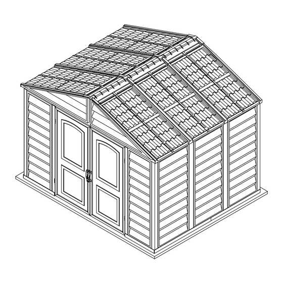
Vinyl Garden Shed
Vinyl Garden Shed
OWNER'S MANUAL /
Instructions for Assembly '10 Ft WoodSide'
Size 10 Ft x 8 Ft / 3.2 m x 2.4 m
Ver: 0.0
Your Total Solution To Maintenance Free Storage Sheds.
• All Weather Durable PVC
• Won't Dent, Rust, Rot or Mildew
• Tall Walk In Shed
• Never Needs Painting
• 61 Inch Wide Double Doors
• Easy Assembly
• High Wind Tested
• Snow Load Tested 20lbs/sq. foot
• Pad Lock Ready (Lock not included)
• Wooden or Cement Foundation Needed
Available Kits
• Foundation Kit Available
• Modular 2.5 Ft Extension Kits Available
• 10 Ft x 8 Ft Window Kits Available
Approximate
Size
Area
10 Ft x 8 Ft
79 Sq. Ft
7.3 Sq.m
3.2 m x 2.4 m
TM
A Product of
S H E D S
Building Dimensions :
Storage
Base Dimension
Volume
480 Cu.Ft
Width
Depth
13.6 Cu.m
Height
(Approx.)
Requires two people and takes about
4-5 hours for Installation.
Exterior Dimension
Roof Edge to Edge
inch
cm
inch
125 3/8
318.4
125 1/2
94 1/4
239.3
95 1/8
91
Customer
Service Hotline
(800) 483-4674
www.uspolymersinc.com
Call us for any missing or damaged parts.
Do not return to the store.
Interior Dimension
Wall to Wall
cm
inch
cm
318.7
123 3/8
313.3
60 5/8
241.6
92 1/4
234.3
231.2
185.5
73
71 1/2
Door Opening
inch
cm
154
181.6
Advertisement

Related Manuals for USP DURAMAX 10 Ft WoodSide


Summary of Contents for USP DURAMAX 10 Ft WoodSide
- Page 1 A Product of A L L P U R P O S E V I N Y L G A R D E N S H E D S Vinyl Garden Shed Vinyl Garden Shed OWNER’S MANUAL / Instructions for Assembly ‘10 Ft WoodSide’ Size 10 Ft x 8 Ft / 3.2 m x 2.4 m (Approx.) Ver: 0.0...
- Page 2 Duramax Garden Shed Limited Fifteen Year Warranty U.S. Polymer Inc. will send a replacement part free of charge, in the event of material defects and or workmanship for a period of fifteen years from the date of purchase. This warranty is extended only to the original purchaser. A purchase receipt or other proof of date of original purchase will be required before warranty service is rendered.
- Page 3 SAFETY & PRECAUTIONS Before You Begin... 1. Check your local building codes regarding footings, location, etc. 2. Select a site that allows enough working space around the shed. 3. Determine building foundation and anchor system. 4. Read and understand the Owner’s manual enclosed in the package. 5.
- Page 4 SAFETY & PRECAUTIONS For your own safety, please read and follow these instructions during the shed assembly. 1. Always wear work gloves, long sleeves and eye protection during assembly of the shed. Some pieces of the shed contain sharp edges and can cause injury. 2.
- Page 5 IMPORTANT Wear eye protection when using any form of power tools. Do not use voltage power tools in a wet or damp enviornment to avoid electric shock. Do not use any part of the shed as a means of personal support while attaching componets during assembly. The shed must be constructed on a solid base foundation.
- Page 6 Parts List PARTS ACCESSORIES CODE CODE CODE B1LA RS8A1 FDCL B1LA, B1RA, B21, CB1A, CB2A, B1RA RS9A1 B22, B3LA, B3RA CB3XA, CB4A, MJ FDCR RS10A1 B3LA RS11A1 B3RA RS12A1 CB1A RS14A RS1A1, RS3H, RS5A1, RS6A1, RS3LH, RS8A1, RS9A1 RS7A1 CB2A DSH1 CB3XA CB4A...
- Page 7 Exploded View RRS1 RRS1 RRS1 RPA1 RPA1 RPA1 RPA1 RPA1 RPA1 FPRA1 RS2A RS3H RS13A1 RS10A1 FPLA1 RS11A1 RS6A1 RS13A1 RS3LH RS6A1 RS4XA RS2A RS7A1 RS13A1 RS2A RS5A1 RS1A1 RS1A1 RS9A1 RS13A1 RS12A1 RS5A1 RS4XA RS3H RS8A1 FPLA1 RS9A1 DSH1 RS1A1 RS3LH RS2A...
- Page 8 A. Foundation Note : If you have DURAMAX Foundation, please follow instruction manual in that package. If not, follow below wooden platform instruction. DuraMax must be installed on a level wooden Note platform or a level concrete foundation. Wooden Platform (Not Included) The following are the list of lumber and sizes you will need.
- Page 9 B. Base Frame Parts Needed: 1. It is important that these instructions Note Code are followed step by step. 2. All parts are clearly marked and care should B1LA be taken to use the correct one. B1RA 3. Don’t install under windy conditions. B3LA 4.
-
Page 10: Table Of Contents
C. Wall & Columns Parts Needed: Code CDLA CDRA CB1A CB2A CB3XA CB4A All parts are clearly marked and care Note should be taken to use the correct one. CDRA CDRA Right B1RA B1RA CDRA Front Fig.1 Fig.2 2&3 CDRA B1LA B1RA Fig.3... - Page 11 Check the stamped label on top of Note all panels inside. CDRA CDRA Front B1RA Fig.1 B1RA Fig.1 Fig.2 2&3 B1RA Fig.3 Do not tighten the screw. Note Leave it loose Fig.1...
-
Page 12: Cb1A
CDRA CDRA CB1A CB1A CB1A Fig.2 Fig.1 CB4A CDRA CDRA B1RA CB4A 2&3 Fig.2 Fig.1 CB1A CB4A CB4A B1RA Fig.3 CB3XA CB3XA CB3XA CB3XA CB2A CB2A CB2A CB3XA CB3XA... -
Page 13: Cbc
Fig.1 Fig.2 CB1A CB3XA 1&2 CB3XA Fig.2 Fig.1 CB3XA CB3XA CB2A Fig.3 Fig.2 Fig.1 3&4 CB3XA CB3XA CB2A CB2A Fig.4 Fig.3... - Page 14 B3RA Fig.2 Fig.1 2&3 B3RA B3RA Fig.3 Do not tighten the screw. Note Leave it loose. Fig.1 CB2A CB2A Fig.1...
- Page 15 B3RA B3RA Fig.1 Fig.2 CB3XA 1&2 CB3A CB3XA CB3XA Fig.2 Fig.1 CB3XA CB3XA Fig.3 Fig.1 Fig.2 3&4 CB3XA CB3XA CB3XA CB3XA B3RA CB3XA Fig.4 Fig.3...
- Page 16 Fig.1 CB3XA CB3XA Fig.3 B3LA Fig.2 Fig.1 B3LA 2&3 B3LA Fig.3 Fig.2 Do not tighten the screw. Note Leave it loose.
- Page 17 CB3XA CB3XA Fig.1 Fig.2 Fig.1 CB3XA CB2A CB2A 1&2 Fig.2 Fig.1 3&4 CB2A CB2A CB2A CB3XA CB3XA CB3XA Fig.3 Fig.4...
- Page 18 Fig.1 CB3XA CB3XA Fig.2 Fig.3 Fig.1 B1LA B1LA B1LA 2&3 Fig.2 Fig.3 Do not tighten the screw. Note Leave it loose Fig.1...
- Page 19 CB3XA CB3XA Fig.1 CDLA B1LA CDLA CDLA Fig.1 Fig.2 B1LA CDLA CB1A CDLA CB1A 1&3 Fig.1 Fig.2 CB1A CB1A CB3XA Fig.3 After completing the center band Note assembly, fully tighten the four center band fittings (FCB) to the corner column (CCA).
- Page 20 CB4A CDLA CDLA B1LA CB4A 2&3 Fig.1 Fig.2 CB1A CB4A CB4A Fig.3 B1LA CDLA CDRA...
- Page 21 D. Roof Structures Parts Needed: Code Code RS10A1 RS1A1 RS11A1 RS2A RS12A1 RS3LH DSH1 RS3H FDCL RS4XA FDCR RS5A1 RS6A1 RS7A1 RS8A1 RS9A1 RS13A1...
- Page 22 FDCR CDLA CDRA Fig.1 CDRA FDCL CDLA Fig.2...
- Page 23 Roof Structures Assembly RS2A RS10A1 RS1A1 RS9A1 RS13A1 RS13A1 RS9A1 RS8A1 RS3H RS2A RS6A1 RS7A1 RS7A1 RS4XA RS13A1 RS6A1 RS1A1 RS11A1 RS12A1 RS13A1 RS3H RS3LH RS4XA RS4XA RS11A1 RS12A1 RS13A1 RS13A1 RS3LH RS5A1 RS4XA RS2A RS5A1 RS13A1 RS5A1 RS13A1 RS1A1 RS10A1 RS2A RS9A1...
- Page 24 Front roof structure assembly RS1A1 RS1A1 RS1A1 RS9A1 RS1A1 RS1A1 RS8A1 RS8A1 RS9A1 RS2A RS1A1 RS9A1 RS8A1 RS8A1 RS2A RS2A RS9A1...
- Page 25 Back roof structure assembly RS1A1 RS1A1 RS1A1 RS9A1 RS1A1 RS1A1 RS8A1 RS8A1 RS9A1 RS2A RS1A1 RS9A1 RS8A1 RS8A1 RS2A RS2A RS9A1...
- Page 26 RS3H RS3H RS3LH RS3H RS3LH RS3LH RS3H RS3LH RS3LH RS3LH RS3H RS3LH RS3LH...
- Page 27 Make Two Sets Note RS6A1 RS5A1 RS13A1 RS6A1 RS13A1 RS5A1 Make Two Sets Note RS7A1 Make Two Sets Note RS5A1...
- Page 28 Note Make Two Sets RS7A1 RS13A1 RS5A1 RS13A1 Front RS2A RS1A1 RS1A1 3&4 CDLA RS1A1 FDCR CDRA 1&2 Fig.1 Fig.2 CDRA RS1A1 RS1A1 FDCL CDLA Fig.3 Fig.4...
- Page 29 Front RS1A1 RS1A1 DSH1 RS1A1 DSH1 DSH1 Fig.1 Fig.2 1&2 DSH1 Fig.3 Back RS1A1 RS1A1...
- Page 30 RS3H RS1A1 RS3LH RS1A1 RS3H Fig.1 Fig.2 RS3LH 1,2,3&4 RS2A RS3LH Fig.3 Fig.4 RS3LH...
- Page 31 RS5A1 RS5A1 RS6A1 RS7A1 RS8A1 RS8A1 Fig.1 RS5A1 RS5A1 RS8A1 RS8A1 Fig.2 RS6A1 RS5A1 RS7A1 RS9A1 RS5A1 Fig.1 RS5A1 RS6A1 RS9A1 Fig.2...
- Page 32 RS4XA RS4XA RS4XA RS4XA RS4XA RS5A1 RS3LH RS4XA Fig.1 Fig.2 RS4XA RS5A1 RS4XA RS5A1 Fig.3 Make sure the hole in (RS10A1) Note RS10A1 facing outward on both sides. RS11A1 RS5A1 RS6A1 RS11A1 RS10A1 RS10A1 RS7A1 RS10A1 Fig.1 Fig.2 RS11A1 RS5A1 RS5A1 Fig.3...
- Page 33 RS6A1 RS5A1 RS12A1 RS7A1 RS5A1 RS12A1 RS12A1 RS5A1...
- Page 34 D. Roof Panels Insert roof plugs into Facia Panel Note only as indicated. Parts Needed: Code RPA1 FPLA1 FPRA1 RRS1 RS14A FPRA1 Use the same colour Plugs & Pins Note (PPG & PIN) to fix the Roof Panels & Facia Panels . FPLA1 FPRA1 Front...
- Page 35 1. Use a screw driver to align the holes. Apply silicone around the roof plugs. Note Note 2. Insert roof plugs into roof panels This is optional and should be done only as indicated. for heavy rain areas if needed. RPA1 Front Roof Panel installation by...
- Page 36 RRS1 RPA1 RRS1 RPA1 Front RS14A RS14A RS14A RS5A1 RS14A Outside View Inside View...
- Page 37 E. Door Parts Needed: Code Fig.1 Fig.2 Fig.1 Fig.2...
- Page 38 Apply silicone around the perimeter Note of the base ‘U’ channel. Seal the corners, joints and base of door column. This is optional and should be done for heavy rain areas if needed. Base ‘U’ channel Column Fig.1 Base ‘U’ channel Fig.2...
- Page 39 F. Ventilation Kit Parts Needed: Code TOOLS YOU WILL NEED Power Drill Dia 5/32” (4.2mm) drill bit Dia 1/2” (12.5mm) drill bit Note Ventilation kits can be installed on any of the wall panels or Facia panels. Outside Note Follow the same steps 1- 4 for installing ventilation kit on Facia panels.
- Page 40 High wind area installation instructions Note: To ensure that your shed withstands high winds, you will need the following reinforcement. Parts needed (not included) CODE DESCRIPTION Dia. 4.2 x 16mm. (5/32” x 5/8”) Sheet Metal Screw M6 x 40mm. (1/4” x 1 1/2”) Anchor Bolt Base ‘U’...
- Page 41 RS3H Attach each Side Panel (SP ) on top to the Roof Structure (RS1A1, RS3LH & RS3H). Using a dia. RS1A1 3mm (1/8”) drill with a power drill, make two equal distance holes on the Side Panel through the Roof Structure.
- Page 42 ADDITIONAL ACCESSORIES AVAILABLE These accessories are required in case of heavy snow or high wind areas. Please choose relevant accessories according to your needs. SUPER SUPPORT KIT Extra roof beams for added protection against heavy snow accumulation. For heavy snow area. ANCHOR KIT (Soil) Wire rope with twist augers for sheds installed with foundation (Wood / Metal) on soil.
- Page 43 U.S. Polymers, Inc. 1057 S. Vail Ave Montebello, CA 90640, United States of America English...
Need help?
Do you have a question about the DURAMAX 10 Ft WoodSide and is the answer not in the manual?
Questions and answers