Table of Contents
Advertisement
Quick Links
BEDIENUNG UND INSTALLATION
OPERATION AND INSTALLATION
UTILISATION ET INSTALLATION
BEDIENING EN INSTALLATIE
OBSLUHA A INSTALACE
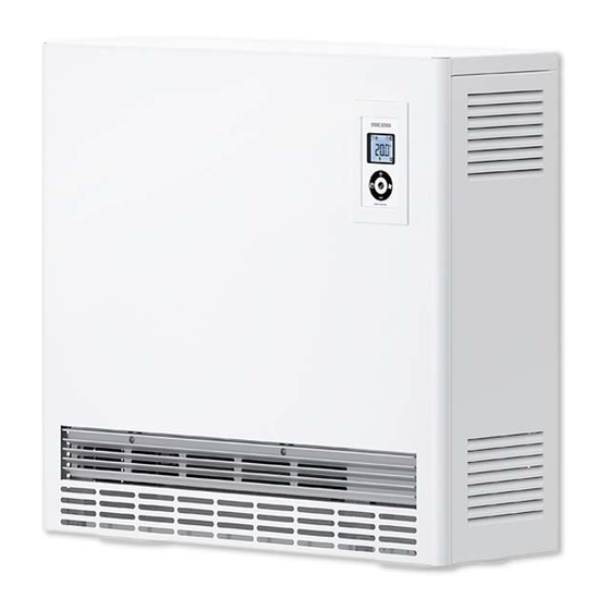
Wand-Flachspeicher | Wall mounted slimline storage heater | Accumulateur plat
mural | platte wand-warmteaccumulator | Plochá nástěnná akumulační kamna
» ETW 120
» ETW 180
» ETW 240
» ETW 300
» ETW 360
» ETW 420
» ETW 480
Advertisement
Table of Contents

Related Manuals for STIEBEL ELTRON ETW 12


Summary of Contents for STIEBEL ELTRON ETW 12
- Page 1 BEDIENUNG UND INSTALLATION OPERATION AND INSTALLATION UTILISATION ET INSTALLATION BEDIENING EN INSTALLATIE OBSLUHA A INSTALACE Wand-Flachspeicher | Wall mounted slimline storage heater | Accumulateur plat mural | platte wand-warmteaccumulator | Plochá nástěnná akumulační kamna » ETW 120 » ETW 180 »...
-
Page 2: Table Of Contents
OPErATION GENErAl INfOrmATION OPERATION �������������������������������������������� 24 General information General information ������������������������������������������ 24 The chapter Operation is intended for users and contractors. 1.1 Key �������������������������������������������������������������������� 24 The chapter Installation is intended for contractors. Safety ���������������������������������������������������������� 25 2.1 Correct use ���������������������������������������������������������� 25 Please read carefully. -
Page 3: Safety
OPErATION sAfETY Safety Safety clearances For all objects, such as furniture, net curtains, curtains, textiles Correct use or other flammable or non-flammable materials, the following This appliance is designed to heat living areas. minimum clearances from the appliance, particularly the air outlet grille, must be maintained: This appliance is designed for domestic use. -
Page 4: Equipment Description
OPErATION EqUIPmENT DEscrIPTION Equipment description Operation Properties User interface Electrically generated heat is stored with this appliance. The To operate, flip open the user interface cover on the front panel. electrical heat is generated when the power supply utility enables the supply of cheaper off-peak power. -
Page 5: Factory Settings
This Removing and refitting the fluff filter is available from Stiebel Eltron as a special accessory. Set the required room temperature at the room thermostat, which then automatically regulates the heat transfer via the fan, so the set room temperature is constantly maintained. -
Page 6: What To Do If
OPErATION WHAT TO DO If... What to do if... » Hook the upper edge of the air inlet grille into the locking device screws, and press from below over the catch springs. fault cause remedy » The appliance does not The charge was not set Set the rotary selector Hooking in the air inlet grille... -
Page 7: Installation
INsTAllATION sAfETY Safety been removed by the contractor, by pressing the button in the centre of the high limit safety cut-out. Country-specific safety information All required steps to complete commissioning must be carried out Cutaway by a qualified contractor. During this process, these installation instructions must be observed. -
Page 8: Installation
INsTAllATION INsTAllATION Installation 9.1.3 Fault characteristics of the electronic charge controller The charge controller is factory-set to "positive fault characteristics Installation conditions and preparation (80% PS)", i.e. if the charge control system is faulty (e.g. control Observe the following explanations prior to installation. signal failure), the appliance is fully charged. -
Page 9: Assembly
INsTAllATION AssEmBlY 10. Assembly 10.2.1 Securing the appliance with ground clearance using wall retainers 10.1 Installation location Prior to installing the appliance, secure two wall retainers to the fixing wall, taking the safety clearances into account (for Fire risk dimensions see diagram and/or chapter "Specification"). Ensure that the temperature resistance of the fixing wall is at least 85 °C and that of the floor is at least Risk of damage... -
Page 10: Installation
INsTAllATION AssEmBlY 10.3 Installation » Undo the screws in the front panel and the inner front panel behind it, both at the bottom edge. » Prior to fixing the appliance, ensure the minimum permissible clearances to adjacent objects are maintained. Removing the front panel Minimum clearances Removing the inner front panel... - Page 11 INsTAllATION AssEmBlY » » Slightly lift the r.h. side panel and remove. Secure the appliance according to specification to the floor or wall (see chapter "Installation location" and "Specification"). Slightly lifting the r.h. side panel and removing Securing the wall retainers NN NN NL TA LE` LH LH` LE NN NN NL...
-
Page 12: Inserting Storage Blocks
INsTAllATION AssEmBlY 10.4 Inserting storage blocks Pushing the storage blocks to the back Risk of fire and injury. Check the thermal insulation in the appliance for transport damage. Broken insulation can lead to the casing overheating. Replace faulty thermal insulation. »... -
Page 13: Cleaning The Appliance
INsTAllATION AssEmBlY 10.5 Cleaning the appliance Hooking in inner front panel Clean the appliance after installation and inserting the storage blocks. » For this, remove the air routing assembly. Undoing and removing air routing assembly Hooking in r.h. side panel at the top and bottom ENN NNN L TAL E`LH LH`L ENN NNN L... -
Page 14: Power Connection
INsTAllATION cOmmIssIONING 10.7 Power connection Note For operation with "single wire control" ** (see (see chapter "Specification – connection options") chapter "Specification – connection diagrams"), place The power connection of the heating elements is made with a jumper between "N" and "A2/Z2". 3/N/PE~400 V, or for appliances ETW 120 and 180 also with 1/N/ Observe the appliance type plate. -
Page 15: Troubleshooting
INsTAllATION TrOUBlEsHOOTING 13. Troubleshooting 13.1 Status display for charge controller fault Green No fault – charge controller is working perfectly. Fault – the rotary selector for charging (R1) and/or the core sensor (B1) are faulty or not connected. No charging occurs. Orange Fault (only for integral discharge controller). -
Page 16: Changing The Fuse
INsTAllATION mAINTENANcE 13.3 Changing the fuse 13.4 Symbols on the type plate Changing the fuse Type plate example 000000 0000 000000 Fine fuse 5x20 mm 2A (slow) Symbols on the type plate (example ETW 120) As additional protection, there is a replaceable fuse for Total weight the electronic charge controller in the switching circuit. -
Page 17: Specification
INsTAllATION sPEcIfIcATION 15. Specification 15.1 Positioning Installation details >70 >100 80,5 (162) Ø9 * Installation with ground clearance possible; see point 2.4.2 "Securing the appliance with ground clearance using wall retainers" Positioning ETW 120 ETW 180 ETW 240 ETW 300 ETW 360 ETW 420 ETW 480... -
Page 18: Reducing The Connected Load
INsTAllATION sPEcIfIcATION 15.2 Reducing the connected load Indication options Connection versions 100% 91.6% 83.3% 100% Types 8 h heating element ETW 120 ETW 180 1.65 1.35 ETW 240 ETW 300 2.75 2.25 ETW 360 ETW 420 3.85 3.15 ETW 480 Connection versions 75% P 100 % P... -
Page 19: Output Matching (Rated Charge Duration)
INsTAllATION sPEcIfIcATION 15.3 Output matching (rated charge duration) Heating elements version Rated charge duration Connection versions Types ETW 120 ETW 180 1.65 ETW 240 ETW 300 2.75 ETW 360 ETW 420 3.85 ETW 480 Connection versions L3 L2 L1 N L3 L2 L1 3/N/PE ~ 400 V L3 L2 L1 N L3 L2... -
Page 20: Connection Diagrams
INsTAllATION sPEcIfIcATION 15.4 Connection diagrams Optional connections Connection diagram for integral room thermostats RTI-E3/RTI-EP2 (N ) * Jumpers (L)-(L-SH) and (N)-(N) Remove for control without heating contactor Charge control system LV system Charge control system 230 V system Charge control system A1/A2 1/N ~ 230 V L1/L2/L3 (if necessary via heating contactor) -
Page 21: Appliance Wiring Diagram
INsTAllATION sPEcIfIcATION 15.5 Appliance wiring diagram Wiring diagram Wiring diagram layout Special accessories Electronic charge controller (Not part of the standard delivery. Tick the boxes for each special User interface PCB accessory installed.) Core sensor – charge (at 20 °C ≈ 541 X) E1-E6 Heating elements RTI-E3 RTI-EP2... -
Page 22: Customer Service And Warranty
CUSTOMER SERVICE AND WARRANTY - ENVIRONMENT AND RECYCLING Guarantee The warranty conditions of our German companies do not apply to appliances acquired outside of Germany. In countries where our subsidiaries sell our products, it is increasingly the case that warranties can only be issued by those subsidiaries. Such warranties are only granted if the subsidiary has issued its own terms of warranty. - Page 23 Deutschland Verkauf Tel. 05531 702-110 | Fax 05531 702-95108 | info-center@stiebel-eltron.de STIEBEL ELTRON GmbH & Co. KG Kundendienst Tel. 05531 702-111 | Fax 05531 702-95890 | kundendienst@stiebel-eltron.de Dr.-Stiebel-Straße 33 | 37603 Holzminden Ersatzteilverkauf Tel. 05531 702-120 | Fax 05531 702-95335 | ersatzteile@stiebel-eltron.de Tel.
Need help?
Do you have a question about the ETW 12 and is the answer not in the manual?
Questions and answers