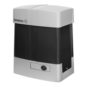
Summary of Contents for Beninca CP.BULL OMI
- Page 1 CP.BULL OMI UNIONE NAZIONALE COSTRUTTORI AUTOMATISMI PER CANCELLI, PORTE SERRANDE ED AFFINI...
- Page 3 15AT 250Vac BRAKE RESISTOR Shield 24 Vdc 0.5A SERVICE LIGHT PHOTO TEST (fig.15) OPEN/CLOSE CON1 /DAS II°Ch. Radio JP1 BAR JP1 BAR Open Close DAS N.C. DAS 8K2...
- Page 4 PHOTOTEST OPEN PHOTOTEST CLOSE OPEN LOG MINV=OFF LOGIC MINV OPEN LOG MINV=OFF OPEN LOG MINV=ON OPEN MAX 16A 250Vac LOG MINV=ON SCA 24Vac AUX: 0 SERVICE LIGHT Aux: 1 MAX 16A 250Vac Service Light 230V...
- Page 5 BAR LOGIC=ON OPEN Close Safety Edge MOTOR Open Safety Edge bar:On (8K2/N.O. Jumper) PHOTO N.C. Open Close DAS N.C. DAS 8K2...
- Page 6 Display OFF Power ON Firmware Ver. (3s) v1. 0 0 8888 Diagnostic tacc tdec tsmo tsmc spin fsto fstc sldo sldc IBCA seav sear ltca pho1 pho2...
- Page 7 tst1 tst2 minv Nman 0012 3456 MACI 2 Cycle AUTO PUSH OPEN/CLOSE RE-ENTER CODE 0000 9000 9C5a conf CODE mot1 YAK 25 BULL 15OMI 115Vac BULL 15OMI 230Vac _ _ _ _ _ _ Display OFF Legenda Premere simultaneamente (+) e (-) / Press simultaneously keys (+) and (-) Premere il tasto (-) / Press key (-) / Die Taste (-) drücken Gleichzeitig (+) und (-) drücken / Presser simultanément (+) et (-) Appuyez sur la touche (-) / Presionar la tecla (-) / Wcisnąć...
- Page 8 WARNING The product shall not be used for purposes or in ways other than those for which the product is intended for and as described in this manual. Incorrect uses can damage the product and cause injuries and damages. The company shall not be deemed responsible for the non-compliance with a good manufacture technique of gates as well as for any deformation, which might occur during use.
- Page 9 2) CP.BULL 15 OMI CONTROL UNIT 2.1) INPUT/OUTPUT FUNCTIONS N° Terminals Function Description Single-phase power input. L-N-GND Power Supply L: Phase - N: Neutral - GND: Ground connection to the motor housing. Note: the ground connection must be done as shown in the diagram at page ??? U-V-W Single-phase motor Single-phase motor connection Phase-Common-Phase.
- Page 10 4) TO ACCESS PROGRAMMING 1 – Press the button <PG>, the display goes to the first menu, Parameters “PAR”. 2 – With the <+> or <-> button, select the menu you want. 3 – Press the button <PG>, the display shows the first function available on the menu. 4 –...
- Page 11 The trigger time of the anti-crash device (Amperometric) is adjusted during the sEar braking phase*. 0-90-(1%) 0:Off-99: maximum sensibility - 1: minimum sensitivity Adjusts the braking space after the limit switch in open position. Value expressed in cm. 1-10-(3) See section “Speed and slowdown settings”*. Adjusts the braking space after the limit switch in close position.
- Page 12 The Service Man function is enabled or disabled. On: Service Man operation. The OPEN/CLOSE push buttons should be kept (OFF) pressed for the entire operating time. Off: Automatic operation. During the TCA time, the blinker is enabled or disabled. LTCA On: Enables blinker.
- Page 13 AUTOSET (AUTO) The automatic system stroke is self learned. See section “STROKE SELF-LEARNING” PASSWORD (CODE) It allows to type in an access protection code to the programming of the control unit. A four-character alphanumeric code can be typed in by using the numbers from 0 to 9 and the letters A-B-C-D-E-F. The default value is 0000 (four zeros) and shows the absence of a protection code.
- Page 14 6) HOW TO ADJUST SPEED AND BRAKING The door/gate stroke is shown in the following scheme: stop phot SWO (SWC) SWC (SWO) FSTo/fstc sldo/SldC TAcc Tdec BLo/blc TSMo/tsmc The V axis is the gate/door speed, T axis is the time required by the door/gate to move from a limit switch to the other. The parameters govern both the opening and the closing phases.
- Page 15 The motor starts in SLOWDOWN mode until it finds SWO then it stops and changes direction always in SLOWDOWN mode until it finds SWC (the stroke is learned). After this the motor performs the first maneuver at regural speed from SWC to SWO (ramps, speeds, slowdowns defined from the parameters TSMo/TSMc/FSTo/FSTc/SLDo/SLDc pre-set) and then it performs the second maneuver at regular speed from SWO to SWC.


Need help?
Do you have a question about the CP.BULL OMI and is the answer not in the manual?
Questions and answers