Table of Contents
Advertisement
Quick Links
Download this manual
See also:
Service Manual
Advertisement
Chapters
Table of Contents

Related Manuals for mundoclima MUCR-H6 Series


Summary of Contents for mundoclima MUCR-H6 Series
- Page 1 DUCT SERIE H6 Installation and owner's manual MUCR-H6 (V2) Thank you very much for purchasing our products. CL20250 to CL20258 Please read this manual carefully before installing English and using the unit. www.mundoclima.com...
- Page 2 CONTENT INSTALLATION MANUAL ..................... 3 OWNER'S MANUAL ....................27 WIRED CONTROLLER ....................37 IMPORTANT Thank you for selectiong super quality Air Conditiones. To ensure satisfactory operation for many ears to come, this manual should be read carefully before the installation and before using the air conditioner. After reading, store it a safe place.
-
Page 3: Installation Manual
INSTALLATION MANUAL Please read this manual carefully before installing and using the unit. INVERTER SPLIT-TYPE ROOM AIR CONDITIONER The design and specifications are subject to change without prior notice for product improvement. Read This Manual: Inside you will find many helpful hints on how to use and maintain your air conditioner properly. -
Page 4: Table Of Contents
INSTALLATION MANUAL Install according to this installation instructions strictly. CONTENTS PAGE If installation is defective, it will cause water leakage, electrical PRECAUTIONS .................4 shock and fire. INSTALLATION INFORMATION ............5 When installing the unit in a small room, take measures ACCESSORIES ...................6 against to keep refrigerant concentration from exceeding... -
Page 5: Installation Information
INSTALLATION MANUAL If the refrigerant leaks during installation, ventilate the area There are inflammable materials or gas. immediately. There is acid or alkaline liquid evaporating. Toxic gas may be produced if the refrigerant comes into the place contacting with fire. Other special conditions. -
Page 6: Accessories
INSTALLATION MANUAL ACCESSORIES Please check whether the following fittings are of full scope. If there are some spare fittings , please restore them carefully. NAME SHAPE QUANTITY 1. Soundproof / insulation sheath Tubing & Fittings 2. Binding tape 3.Seal sponge 4. -
Page 7: Indoor Unit Installation
INSTALLATION MANUAL INDOOR UNIT INSTALLATION 1.2 Install the main body Installing 10 hanging screw bolts. (4 bolts) Installation place Please refer to the following figures for positioning 4 screw bolts. The indoor unit should be installed in a location that meets the Evaluate the ceiling construction and please install with following requirements: hanging screw bolts. - Page 8 INSTALLATION MANUAL 1.2.4 Steel roof beam structure Install and use directly the supporting angle steel. Hanging screw bolt Supporting Hanging bolts angle steel Overhanging the indoor unit (1) Overhang the indoor unit onto the hanging screw bolts with block. (2) Position the indoor unit in a flat level by using the level indicator, unless it may cause leakage.
-
Page 9: Important Safety Information
INSTALLATION MANUAL The positioning of ceiling hole, indoor unit and hanging screw bolts Dimension and air outlet size Fresh air intake (See pag. 22) Air inlet size Air filter Position size of ventilation opening Air filter Electric control box Size of mounted hook Electric control box Unit: mm Size of... - Page 10 INSTALLATION MANUAL How to adjust the air inlet direction? (From rear side to under-side.) Take off ventilation panel and flange, cut off the staples at Stick the attached seal sponge as per the indicating place in side rail. the following fig, and then change the mounting positions of air return panel and air return flange .
- Page 11 INSTALLATION MANUAL Fan performances Static pressure curve (middle static pressure duct) MUCR-12-H6 MUCR-12-H6 FOR SETTING STATIC PRESSURE ENC2 CODE 0 Pa 10 Pa 20 Pa 30 Pa 40 Pa MODEL 18 to 24 10 Pa 25 Pa 40 Pa 55 Pa 70 Pa 30 to 60 20 Pa...
- Page 12 INSTALLATION MANUAL MUCR-18-H6 FOR SETTING STATIC PRESSURE ENC2 CODE 0 Pa 10 Pa 20 Pa 30 Pa 40 Pa MODEL 18 to 24 10 Pa 25 Pa 40 Pa 55 Pa 70 Pa 30 to 60 20 Pa 35 Pa 50 Pa 65 Pa 80 Pa...
- Page 13 INSTALLATION MANUAL MUCR-24-H6 FOR SETTING STATIC PRESSURE ENC2 CODE 0 Pa 10 Pa 20 Pa 30 Pa 40 Pa MODEL 18 to 24 10 Pa 25 Pa 40 Pa 55 Pa 70 Pa 30 to 60 20 Pa 35 Pa 50 Pa 65 Pa 80 Pa...
- Page 14 INSTALLATION MANUAL MUCR-30-H6 FOR SETTING STATIC PRESSURE ENC2 CODE 0 Pa 10 Pa 20 Pa 30 Pa 40 Pa MODEL 18 to 24 10 Pa 25 Pa 40 Pa 55 Pa 70 Pa 30 to 60 20 Pa 35 Pa 50 Pa 65 Pa 80 Pa...
- Page 15 INSTALLATION MANUAL MUCR-36-H6 FOR SETTING STATIC PRESSURE ENC2 CODE 0 Pa 10 Pa 20 Pa 30 Pa 40 Pa MODEL 18 to 24 10 Pa 25 Pa 40 Pa 55 Pa 70 Pa 30 to 60 20 Pa 35 Pa 50 Pa 65 Pa 80 Pa...
- Page 16 INSTALLATION MANUAL MUCR-42-H6 MUCR-48-H6 MUCR-48-H6T MUCR-60-H6T FOR SETTING STATIC PRESSURE ENC2 CODE 0 Pa 10 Pa 20 Pa 30 Pa 40 Pa MODEL 18 to 24 10 Pa 25 Pa 40 Pa 55 Pa 70 Pa 30 to 60 20 Pa 35 Pa 50 Pa 65 Pa...
-
Page 17: Outdoor Unit Installation
INSTALLATION MANUAL OUTDOOR UNIT INSTALLATION Figure of body size Precautions for selecting the location 1) Choose a place solid enough to bear the weight and vibration of the unit, where the operation noise will not be amplified. 2) Choose a location where the hot air discharged from the unit or the operation noise will not cause a nuisance to the neighbours of the user. - Page 18 INSTALLATION MANUAL 2.4 Outdoor unit installation 2.3 Installation guidelines Where a wall or other obstacle is in the path of outdoor unit 1) Installing outdoor unit inlet or outlet airflow, follow the installation guidelines below. When installing the outdoor unit, refer to "Precautions for For any of the below installation patterns, the wall height on the selecting the location"...
-
Page 19: Install The Refrigerant Pipe
INSTALLATION MANUAL INSTALL THE REFRIGERANT PIPE 3.1 Flaring the pipe end 1) Cut the pipe end with a pipe cutter. All field piping must be provided by a licensed refrigeration 2) Remove burrs with the cut surface facing downward so that the technician and must comply with the relevant local and chips do not enter the pipe. - Page 20 INSTALLATION MANUAL 3.3 Purging air and checking gas leakage Pipe length Up to 15m More than 15m When piping work is completed, it is necessary to purge the Run time Not less than 10 min Not less than 15min air and check for gas leakage. *2.
-
Page 21: Connect The Drain Pipe
INSTALLATION MANUAL CONNECT THE DRAIN PIPE 2) Be sure to insulate both the gas and liquid piping. Use separate thermal insulation pipes for gas and liquid 4.1 Install the drain pipes. refrigerant pipes. See the figure below. Keep piping as short as possible and slope it downwards at a gradient of at least 1/100 so that air may not remain trapped inside the pipe. - Page 22 INSTALLATION MANUAL 4.3 Testing of drain piping 4.4 Fresh air duct installation Check whether the drainpipe is unhindered. Dimension : New built house should have this test done before paving the ceiling. Duct joint for fresh air The unit with pump. 1.
-
Page 23: Electric Wiring Work
INSTALLATION MANUAL Minimum nominal cross-sectional ELECTRIC WIRING WORK area of conductors: General instructions Rated current Nominal cross-sectional of appliance area All field wiring and components must be installed by a licensed (mm2) electrician and must comply with relevant European and national <6 0.75 regulations. - Page 24 INSTALLATION MANUAL Connecting wiring MUCR-48/60-H6T MUCR-18/24/30/36/42/48-H6 INDOOR UNIT INDOOR UNIT INDOOR UNIT INDOOR UNIT 230 Vac 230 Vac 50 Hz 50 Hz 230 Vac 230 Vac 50 Hz 50 Hz Note: Only Twin (2x1) Note: Only Twin (2x1) 230 Vac 400 Vac 50 Hz 50 Hz...
- Page 25 The capacity of the unit, the address of the unit, temperature compensation, etc. it can be setting by remote control RG57 or by indoor dip-switch. For more information, please contact the after-sales service Mundoclima, with your sales man or visit www.mundoclima.com in the corresponding model section you will find the parameters setting manual.
-
Page 26: Refrigerant Pipe (The Unit With The Twins Function)
INSTALLATION MANUAL 6.3 Size of joint pipes for outdoor unit REFRIGERANT PIPE (the unit with the twins Base on the following tables, select the diameters of the outdoor function) unit connective pipes. In case of the main accessory pipe large than the main pipe, take the large one for the selection. - Page 27 OWNER´S MANUAL Please read this manual carefully before installing and using the unit. INVERTER SPLIT-TYPE ROOM AIR CONDITIONER The design and specifications are subject to change without prior notice for product improvement. Read This Manual: Inside you will find many helpful hints on how to use and maintain your air conditioner properly.
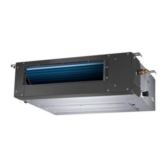
- Page 28 OWNER'S MANUAL OUTDOOR UNIT INDOOR UNIT Fig.1 INDOOR UNIT OUTDOOR UNIT Connecting pipe Air outlet Air inlet Air inlet Air filter (on some models) Air inlet (side and rear) Electric control cabinet Air outlet Wire controller Drain pipe NOTE All the pictures in this manual are for explanation purpose only. They may be slightly different from the air conditioner you purchased(depend on model).The actual shape shall prevail.
- Page 29 OWNER'S MANUAL CONTENTS PAGE Never use a flammable spray such as hair spray,lacquer or paint near the unit. IMPORTANT SAFETY INFORMATION............9 It may cause a fire. PARTS NAMES..................Never touch the air outlet or the horizontal blades while AIR CONDITIONER OPERATIONS AND PERFORMANCE......the swing flap is in operation.
-
Page 30: Parts Names
OWNER'S MANUAL In order to avoid injury, do not remove the fan guard of This appliance is not intended for use by persons the outdoor unit. (including children) with reduced physical, sensory mental capabilities, lack experience Do not operate the air conditioner with a wet hand. knowledge, unless they have been given supervision or An electric shock may happen. -
Page 31: Air Conditioner Operations And Performance
OWNER'S MANUAL 4. HINTS FOR ECONOMICAL OPERATION 3. AIR CONDITIONER OPERATIONS AND PERFORMANCE The following should be noticed to ensure an economical operation. Use the system in the following temperature for safe and (Refer to corresponding chapterfor details) effective operation.The Max operation temperature for the air conditioner.(Cooling/Heating) Adjust the air flow direction properly to avoid winding toward your body. - Page 32 OWNER'S MANUAL Maintenance after a long stop period For your purchasing unit is a descensional ventilated one, please push the filter up slightly to let the position retainer escape away (eg. at the beginning of the season) from the flange fixed holes, and take off the filter according to the arrow direction shows in the following fig.
-
Page 33: Following Symptoms Are Not Air Conditioner Troubles
OWNER'S MANUAL Symptom 3.2: Indoor unit, outdoor unit The air-in side should face up when using vacuum cleaner. (Refer to Fig.5-4) When the system is changed over to heating operation after The air-in side should face down when using water. (Refer to defrost operation Moisture generated by defrost becomes Fig.5-3) steam and is exhausted. -
Page 34: Troubleshooting
OWNER'S MANUAL 7. TROUBLESHOOTING 7.1. Troubles and causes of air conditioner CAUTION If one of the following malfunctions occur, stop operation, shut Please cut off the power supply when appearing the off the power, and contact with your dealer. above malfunction, check if the voltage provided is out of The operation lamp is flashing rapidly (5Hz). - Page 35 OWNER'S MANUAL Table 7-2 Outdoor unit error codes (Models 18 to 60) Nº Code Description Communication malfunction beetwen indoor and outdoor units Current overload protection Outdoor room temperature sensor (T4) open circuit or short circuit Outdoor coil temperature sensor (T3) open circuit or short circuit Outdoor discharge temperature sensor (T5) open circuit or short circuit Outdoor EEPROM error Outdoor fan speed malfunction...
- Page 36 OWNER'S MANUAL 7.2. Troubles and causes of wire controller Before asking for serving or repairing , check the following points. (Refer to Table 7-4) Table 7-4 Symptoms Solution Causes Check whether the MODE When the automatic mode is indicated on the display is selected, the air conditioner will "AUTO"...
- Page 37 WIRED CONTROLLER ● This manual gives detailed description of the precautions that should be brought to your attention during operation. ● In order to ensure correct service of the wired controller please read this manual carefully before using the unit. ●...
- Page 38 WIRED CONTROLLER I. Safety precautions The following contents are stated on the product and the operation manual, including usage, precautions against personal harm and property loss, and the methods of using the product correctly and safely. After fully understanding the following contents (identifiers and icons), read the text body and observe the following rules.
-
Page 39: Installation Method
WIRED CONTROLLER 2. Installation accessory 2.1 Select the installation location Don’t install at the place where cover with heavy oil, vapor or sulfureted gas, otherwise, this product would be deformed that would lead to system malfunction. 2.2 Preparation before installation 1. - Page 40 WIRED CONTROLLER 2. Remove the upper part of wire controller Insert a slot screwdriver into the slots in the lower part of the wire controller (2 places), and remove the upper part of the wire controller. (Fig.3-2) NOTICE The PCB is mounted in the upper part of the wire Slots controller.
- Page 41 WIRED CONTROLLER 5. Wire the indoor unit 4 methods 1 from the rear; 2 from the bottom; 3 from the top; 4 from the top center. HA HB HA HB HA HB HA HB 1 indoor unit 2 notch the part for the wiring to pass through with nippers, etc. Connect the terminals on the remote controller (HA ,HB), and the terminals of the indoor unit (HA ,HB).
-
Page 42: Wiring Specifications
WIRED CONTROLLER 4. Specification DC 5V/DC 12V Input voltage Ambient temperature -5~43℃(23~110℉) RH40%~RH90% Ambient humidity Wiring specifications Wiring type Total length Size Shielded vinyl cord or cable 0.75-1.25mm <50m Copy/ Swing Timer Day off/Del Confirm Back/Turbo Follow me... - Page 43 WIRED CONTROLLER 6. Name on the LCD of the wire controler 1 Operation mode indication 8 Turbo function indication 2 Fan speed indication 9 C° / F° indication 3 Left-right swing indication 10 Temperature display 4 Up-down swing indication 11 Lock indication 5 Faceplate function indication 12 Room temperature indication 6 Main unit and secondary unit indication...
- Page 44 WIRED CONTROLLER 8. Preparatory operation Set the current day and time Timer Press the TIMER button for 3 seconds or more. The timer display will flash. Press the button “ + ” or “ - ” to set the date. The selected date will flash.
- Page 45 WIRED CONTROLLER Fan speed setting Press the FAN SPEED button to set the fan speed. (This button is unavailable when in the mode of Auto or Dry) Fan speed (Lock) Room temperature sensor selection Copy/ Follow me Indoor Unit Press the Follow me button to select whether the room temperature is detected at the indoor unit or the wire controller.
- Page 46 WIRED CONTROLLER Faceplate function (on some models) 1.When the unit is off, Press the Mode(A/B) button long to activate the faceplate function. The mark will flash. Mode The F2 mark appears when the faceplate is adjusted. 2. Push the Mode(A/B) button to select Unit A or Unit B, the wire controller select in a sequence that goes from (this step do not need to perform if the wire controller is connected with one unit only): 3.
- Page 47 WIRED CONTROLLER 10. Timer functions On timer Use this timer function to start air conditioner operation.The timer operates and air conditioner operation starts after the time has passed. Off timer Use this timer function to stop air conditioner operation.The timer operates and air conditioner operation stops after the time has passed.
- Page 48 WIRED CONTROLLER To set the On and Off TIMER Timer Press the TIMER button to select the Confirm Press the CONFIRM button and the Clock display is flashing. Confirm Press the button “ + ” or “ - ” to set the time of On timer, and then press the CONFIRM button to confirm the setting.
- Page 49 WIRED CONTROLLER Time setting Confirm Press the button “ + ” and “ - ” to set the time.and then press the Confirm button to confirm the setting. Operation mode setting Press the button “ + ” and “ - ” to set the operation mode .and then press the Confirm Confirm button to confirm the setting.
- Page 50 WIRED CONTROLLER ● To turn off the air conditioner during the weekly timer 1. If press the Power button once and quickly , the air conditioner will turn off temporarily. And the air conditioner will turn on automatically until the time of On timer.
- Page 51 WIRED CONTROLLER Confirm During the weekly timer, press the Confirm button. Press the button “ + ” or “ - ” to select the day to copy from. Copy/ Press the Copy button,the letter “CY” will be Follow me shown on the LCD. Press the button “...
- Page 52 ASK FOR MORE INFORMATION Phone: (+34) 93 446 27 81 eMail: info@mundoclima.com TECHNICAL ASSISTANCE Phone: (+34) 93 652 53 57 www.mundoclima.com...
Need help?
Do you have a question about the MUCR-H6 Series and is the answer not in the manual?
Questions and answers