
Subscribe to Our Youtube Channel
Related Manuals for WHALETEQ CMRR 3.0E


Summary of Contents for WHALETEQ CMRR 3.0E
- Page 1 CMRR 3.0E | User Manual WHALETEQ Common Mode Rejection Ratio Tester For IEC80601-2-26:2019 CMRR 3.0E User Manual (Revision 2020-09-03) PC Software Version V1.0.6.9...
- Page 2 WhaleTeq Co. LTD. Disclaimer WhaleTeq Co. LTD. provides this document and the programs "as is" without warranty of any kind, either expressed or implied, including, but not limited to, the implied warranties of merchantability or fitness for a particular purpose.
-
Page 3: Table Of Contents
CMRR 3.0E | User Manual Table of Contents Introduction Electrical Diagram Set Up a Noise Free Test Environment Reduce environmental noise and connect outer shielding to the ground plane. Shielding Covers for the Electrode Cables Principle of the CMRR test... - Page 4 CMRR 3.0E | User Manual Ordering Information Package Contents Optional Software and Accessories 10 Contact Information...
-
Page 5: Introduction
Therefore, the Monitor terminal voltage shall be Vc/11 Vrms. CMRR 3.0E is equipped with a touch screen which enables to adjust and display all required test parameters on the screen. Via USB interface connection, CMRR 3.0E can be controlled by PC software or SDK (Software Development Kit). -
Page 6: Set Up A Noise Free Test Environment
CMRR 3.0E | User Manual Figure 2-1, CMRR 3.0E Electrical Diagram Item: Signal generator Internal connection wires Electrode terminals ±150 mV DC Power Source Inner Shield Outer Shield Isolated control circuit (electrode) isolated control circuit (signal generator) Voltage monitor (Vs, Vc) -
Page 7: Shielding Covers For The Electrode Cables
Figure. 3-1, Set-up CMRR 3.0E Test Environment Shielding Covers for the Electrode Cables (1) Please fasten the bottom shielding cover to the right-side panel of CMRR 3.0E for reducing main frequency interference. (see Figure.3-2) Figure. 3-2, CMRR 3.0E with bottom shielding cover (2) As the bottom shielding cover is connected to Vc, Vc would be unstable due to the outer noise. -
Page 8: Principle Of The Cmrr Test
Even 100MΩ/3pF will load the circuit, so the voltage will change (increase) by about 5% after the HV probe is removed, which should be accounted for if such probes are used. WhaleTeq CMRR 3.0E equipment resolved the difficulty in measuring Vc by using 110MΩ/10MΩ 11:1... -
Page 9: Panel Function
+/- 150mV DC offset with different imbalanced impedance electrodes. The CMRR 3.0E DC offset is supplied by an internal battery. The lifetime of this battery is estimated to be at more than 40 hours under continuous use. Therefore, its time in service should be long enough for tests that only last a few seconds each time. -
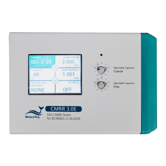
Page 10: Lcd Touch Screen
CMRR 3.0E | User Manual Figure 5-1, the upper panel of CMRR 3.0E The whole CMRR 3.0E operation can be done with the knobs on the upper panel. All of the parameters can be shown on the LCD touch screen. -
Page 11: 70.71 Vrms Switch
Under the manual mode, the [70.71 Vrms] option can be selected to test a higher CMRR value. Front Panel The front panel of CMRR 3.0E is shown in figure 5-2. Please see instruction to each terminal as below: Figure 5-2, the front panel of CMRR 3.0E Connectors on the front panel are mainly used for power supply, USB connection and calibration. -
Page 12: Power Switch
Outer shield grounding that connects the metal sheet in figure 3-1 in tests to reduce noises. Right Panel The right panel of CMRR 3.0E is shown in figure 5-3. It is mainly used to connect each electrodes of EEG. Figure 5-3, the right panel of CMRR 3.0E... -
Page 13: Cm Point] Terminal
[On]. All of the operations of CMRR 3.0E can be done with the touch screen and knobs on the upper panel. All the parameters can be displayed on the LCD touch screen. - Page 14 CMRR 3.0E | User Manual 6.1.1.2 [Supply Voltage] and [Frequency] Select [Manual] in [Standard] option, and then select [Voltage]. Now the [Voltage] can choose [Off], [20], [2.828], [0.5] and [2.0] Vrms (200/56.6/8/1.422/5.66 Vpp) for Supply Voltage Vs (the output voltage of built-in sine wave signal generator) and 50/60/100/120 Hz for frequency.
- Page 15 Adding 10KΩ/47nF to one of the electrodes, or all the electrodes except one, with the others in the opposite, is referred to imbalanced test. Available settings for CMRR 3.0E are as follows: Electrode with Impedance: None, none of the electrodes is added 10KΩ//47nF parallel circuit, balanced test Electrode with Impedance: RA (LA/LL/V1~V6), only RA (LA/LL/V1~V6) is added 10KΩ//47nF and...
-
Page 16: Test Exemplification
100 µVp-v (10 mm p-v at 0.1 mm/µV gain), WhaleTeq suggests use RA/LA/LL/V1/V2/V3/V4/V5/V6 terminals to proceed balance and imbalance tests with DC offset options. This is to ensure the absolute balance of CMRR 3.0E output signals and increase the precision of CMRR test. -
Page 17: Pc Software Operation
18. Repeat the switch procedures until Chn is measured PC Software Operation CMRR 3.0E can be connected to PC via USB cable. Once connect to PC, CMRR 3.0E can be controlled and commanded through PC software. User can also develop software by using CMRR 3.0E SDK (Software Development Kit) to fulfill automated test requirements. -
Page 18: Cmrr 3.0E Assistant Software
6.2.2 CMRR 3.0E Assistant Software Refer to figure 6-7 for software interface of CMRR 3.0E Assistant Software. This is mainly used to support test sequences required by IEC80601-2-26:2019. CMRR 3.0E Assistant Software can effectively simplify the complication of switching different test parameters. - Page 19 6-8. The blue-shaded description texts in [Test Sequence] change as the test steps proceed. This makes the user to have a better understanding of the test sequences. Figure 6-8, Software interface and test sequence description of CMRR 3.0E Assistant 6.2.2.2 Step 2. Frequency Setting Set the line frequency to either 50Hz or 60Hz, or both.
- Page 20 CMRR 3.0E | User Manual As the stray capacitance of patient cable affects the 100 pF capacitance value in CMRR 3.0E, Vc should be tuned after detaching patient cable. 6.2.2.4 Test Parameter Setting Choose [Manual] of [Automatic] test. If manual test is chosen and [Test Sequence] is opened, the right window in figure 6-9 will appear after clicking [Run] button.
-
Page 21: Caution
Battery power consumption for DC offset function CMRR 3.0E uses a built-in battery supplying the power required by DC offset option. Before turning off the power, user must check and confirm DC offset is switched to “OFF”. If not, it would keep consuming battery power in the power-off status. -
Page 22: Cmrr 3.0E Specifications
±1% ( 0.25Vrms ±2% ) Frequency 50 / 60 / 100 /120 (Hz) ±1% None/RA/LA/LL/V1~V6 Electrode with Impedance Change electrode via the touch screen of CMRR 3.0E /ALL Electrode without Change electrode via the touch screen of CMRR 3.0E RA/LA/LL/V1~V6 Impedance Imbalance impedance, R 10kΩ...
Need help?
Do you have a question about the CMRR 3.0E and is the answer not in the manual?
Questions and answers