Table of Contents
Advertisement
Quick Links
Advertisement
Table of Contents

Related Manuals for Cisco SKY-MOD1G-HR-A


Summary of Contents for Cisco SKY-MOD1G-HR-A
- Page 1 Cisco Provider Connectivity Assurance Sensor Module 1G Hardware Installation Guide First Published: 2024-09-13 Americas Headquarters Cisco Systems, Inc. 170 West Tasman Drive San Jose, CA 95134-1706 http://www.cisco.com Tel: 408 526-4000 800 553-NETS (6387) Fax: 408 527-0883...
- Page 2 Cisco has more than 200 offices worldwide. Addresses and phone numbers are listed on the Cisco website at www.cisco.com/go/offices. Cisco and the Cisco logo are trademarks or registered trademarks of Cisco and/or its affiliates in the U.S. and other countries. To view a list of Cisco trademarks, go to this URL: https://www.cisco.com/c/en/us/about/legal/trademarks.html.
-
Page 3: Table Of Contents
Site Considerations Power Supply Considerations Rack Configuration Considerations C H A P T E R 3 Mount the Chassis Unpack and Inspect the Chassis Wall-Mount the Chassis Rack-Mount the Chassis Cisco Provider Connectivity Assurance Sensor Module 1G Hardware Installation Guide... - Page 4 Installation, Maintenance, and Upgrade Power the Unit via the AC Power Supply Power the Unit via DC Power Cable Power the Unit via DC Terminal Block Adapter Connect to the Network Cisco Provider Connectivity Assurance Sensor Module 1G Hardware Installation Guide...
-
Page 5: Features
Layer 2 through 4 testing and traffic generation—without compromising performance, scalability, and precision. This makes Assurance Sensor Modules an ideal fit for cost- and space-sensitive applications where performance is a key service differentiator. Cisco Provider Connectivity Assurance Sensor Module 1G Hardware Installation Guide... -
Page 6: Overview
• Rubber feet (4x) • RJ-45 patch cord (1x) • Cisco Provider Connectivity Assurance Sensor Module 1G—This document contains URLs that point to the hardware installation guide, regulatory compliance and safety information guide, warranty, and licensing pages, and a QR code that points to the management center Documentation Portal... -
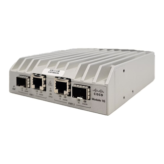
Page 7: Serial Number Locations
Optical port 2 RJ-45 100/1000 Mbps Ethernet Port 2 SFP 1000 Mbps Ethernet Port 2 (combo models only) Hot surface Note that the surface is hot to touch. Electrostatic Discharge Cisco Provider Connectivity Assurance Sensor Module 1G Hardware Installation Guide... -
Page 8: Front Panel Leds
• Flashing—Device is ready, and remotely managed. • Slow flashing means the system is currently managed by a remote controller. • Fast flashing means a critical system failure is detected. Cisco Provider Connectivity Assurance Sensor Module 1G Hardware Installation Guide... -
Page 9: Rear Panel
Secure the AC cord through the retainer clip Connect appropriate power cord here The following figure shows the rear panel of the Sensor Module 1G - DC Input Power Model. Cisco Provider Connectivity Assurance Sensor Module 1G Hardware Installation Guide... -
Page 10: Power Supply
3.4 W for all ports Warning Transceivers used in the ports must stay within their specifications under all operating conditions of the system. Power consumption 7.8 W (27 BTU/hr Cisco Provider Connectivity Assurance Sensor Module 1G Hardware Installation Guide... -
Page 11: Hardware Specifications
Relay - Hardened DHCP enabled SKY-MOD1G-H-A Module 1G - 2xCombo - Single Internal AC Power Supply - Hardened DHCP enabled SKY-MOD1G-H-DD Module 1G - 2xCombo - Dual DC Power Supply - Hardened DHCP enabled Cisco Provider Connectivity Assurance Sensor Module 1G Hardware Installation Guide... -
Page 12: Power Cord Specifications
Brazil – C5 termination SKY-PC-C20 C20 – C5 termination SKY-PC-C14 C14 – C5 termination SKY-PC-CHN China – C5 termination Note Only the approved power cords for the Sensor Module 1G are supported. Cisco Provider Connectivity Assurance Sensor Module 1G Hardware Installation Guide... -
Page 13: Installation Preparation
Use the statement number at the beginning of each warning statement to locate its translation in the translated safety warnings for this device. SAVE THESE INSTRUCTIONS Cisco Provider Connectivity Assurance Sensor Module 1G Hardware Installation Guide... - Page 14 Only an instructed person or skilled person should be allowed to install, replace, or service this equipment. See statement 1089 for the definition of an instructed or skilled person. There are no serviceable parts inside. To avoid risk of electric shock, do not open. Cisco Provider Connectivity Assurance Sensor Module 1G Hardware Installation Guide...
-
Page 15: Safety Recommendations
• The chassis is equipped with an AC-input power supply, which is shipped with a three-wire electrical cord with a grounding-type plug that fits into a grounding-type power outlet only. Do not circumvent this safety feature. Equipment grounding should comply with local and national electrical codes. Cisco Provider Connectivity Assurance Sensor Module 1G Hardware Installation Guide... -
Page 16: Prevent Esd Damage
• Check the power at the site before installing the chassis to ensure that it is free of spikes and noise. Install a power conditioner, if necessary, to ensure proper voltages and power levels in the appliance-input voltage. Cisco Provider Connectivity Assurance Sensor Module 1G Hardware Installation Guide... -
Page 17: Rack Configuration Considerations
• Baffles can help to isolate exhaust air from intake air, which also helps to draw cooling air through the chassis. The best placement of the baffles depends on the airflow patterns in the rack. Experiment with different arrangements to position the baffles effectively. Cisco Provider Connectivity Assurance Sensor Module 1G Hardware Installation Guide... - Page 18 Installation Preparation Rack Configuration Considerations Cisco Provider Connectivity Assurance Sensor Module 1G Hardware Installation Guide...
-
Page 19: Mount The Chassis
Check for damage and report any discrepancies or damage to your customer service representative. Have the following information ready: • Invoice number of shipper (see the packing slip) • Model and serial number of the damaged unit • Description of damage Cisco Provider Connectivity Assurance Sensor Module 1G Hardware Installation Guide... -
Page 20: Wall-Mount The Chassis
• Cable pull—accidental or otherwise—should not exceed the 2.5 kg (5.5 lbs.) limit. Rack-Mount the Chassis To rack-mount the chassis: Step 1 Secure two L-shaped mounting brackets vertically to both sides of each Module using the provided screws. Cisco Provider Connectivity Assurance Sensor Module 1G Hardware Installation Guide... -
Page 21: Ground The Chassis
Step 4 Secure the rack-mount bracket to the rack using the fasteners as recommended by the manufacturer. Ground the Chassis Note Grounding is applicable for the DC Power Input Model only. Cisco Provider Connectivity Assurance Sensor Module 1G Hardware Installation Guide... - Page 22 In the Scandinavian countries (Denmark, Finland, Iceland, Norway, and Sweden) the appliance must be connected to a grounded outlet. Warning For optimal performance, connect the functional ground screw to a suitable grounding point before applying power. Cisco Provider Connectivity Assurance Sensor Module 1G Hardware Installation Guide...
-
Page 23: Installation, Maintenance, And Upgrade
Secure the power cord through the retainer clip. Warning The AC plug must be connected to a properly grounded AC outlet. Power the Unit via DC Power Cable Safety Warnings Take note of the following warning: Cisco Provider Connectivity Assurance Sensor Module 1G Hardware Installation Guide... -
Page 24: Power The Unit Via Dc Terminal Block Adapter
Connect the DC connector to the back of the Module. Figure 9: Connect the DC Connector Power the Unit via DC Terminal Block Adapter Safety Warnings Take note of the following warning: Cisco Provider Connectivity Assurance Sensor Module 1G Hardware Installation Guide... - Page 25 Establish the proper connections between the wires and the power sources. Step 3 Connect wires to the terminal block connector of the adapter. Note Applicable wire range: 0.34 to 4 mm (22 to 12AWG) Cisco Provider Connectivity Assurance Sensor Module 1G Hardware Installation Guide...
-
Page 26: Connect To The Network
The intra-building ports of the equipment or subassembly is suitable for connection to intra-building or unexposed wiring or cabling only. The intra-building ports of the equipment MUST NOT be metallically connected to interfaces that connect to the OSP or its wiring. Cisco Provider Connectivity Assurance Sensor Module 1G Hardware Installation Guide...
Need help?
Do you have a question about the SKY-MOD1G-HR-A and is the answer not in the manual?
Questions and answers