Table of Contents
Advertisement
Quick Links
Doc. No.
78-3052-01
1-Port and 2-Port ISDN-PRI Network Module
Configuration Note
Product Numbers:
NM-1CT1, NM-1CT1-CSU, NM-2CT1, NM-2CT1-CSU, NM-1CE1-B, NM-2CE1-B,
NM-1CE1-U, NM-2CE1-U
CPANM-1CT1, CPANM-1CT1-CSU, CPANM-2CT1, CPANM-2CT1-CSU,
CPANM-1CE1-B, CPANM-2CE1-B, CPANM-1CE1-U, CPANM-2CE1-U
This document provides information about the following network modules for the Cisco 3600 series
of modular access routers:
•
1-port channelized T1/ISDN-PRI network module, Cisco product number NM-1CT1 or
CPANM-1CT1. (See Figure 1.) This module will also be referred to as the 1-port CT1/PRI
network module.
•
2-port channelized T1/ISDN-PRI network module, Cisco product number NM-2CT1 or
CPANM-2CT1. (See Figure 2.) This module will also be referred to as the 2-port CT1/PRI
network module.
•
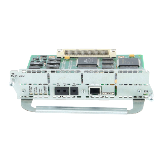
1-port channelized T1/ISDN-PRI with CSU network module, Cisco product number
NM-1CT1-CSU or CPANM-1CT1-CSU. (See Figure 3.) This module will also be referred to as
the 1-port CT1/PRI-CSU network module.
•
2-port channelized T1/ISDN-PRI with CSU network module, Cisco product number
NM-2CT1-CSU or CPANM-2CT1-CSU. (See Figure 4.) This module will also be referred to as
the 2-port CT1/PRI-CSU network module.
•
1-port channelized E1/ISDN-PRI balanced (120-ohm) network module, Cisco product number
NM-1CE1B or CPANM-1CE1B. (See Figure 5.) This module will also be referred to as the 1-port
CE1/PRI-B network module.
Corporate Headquarters
Cisco Systems, Inc.
170 West Tasman Drive
San Jose, CA 95134-1706
USA
Copyright © 1996
Cisco Systems, Inc.
All rights reserved.
1
Advertisement
Table of Contents

Related Manuals for Cisco NM-1CT1


Summary of Contents for Cisco NM-1CT1
- Page 1 • 1-port channelized T1/ISDN-PRI with CSU network module, Cisco product number NM-1CT1-CSU or CPANM-1CT1-CSU. (See Figure 3.) This module will also be referred to as the 1-port CT1/PRI-CSU network module. • 2-port channelized T1/ISDN-PRI with CSU network module, Cisco product number NM-2CT1-CSU or CPANM-2CT1-CSU.
- Page 2 • 2-port channelized E1/ISDN-PRI balanced (120-ohm) network module, Cisco product number NM-2CE1B or CPANM-2CE1B. (See Figure 6.) This module will also be referred to as the 2-port CE1/PRI-B network module. • 1-port channelized E1/ISDN-PRI unbalanced (75-ohm) network module, Cisco product number NM-1CE1U or CPANM-1CE1U.
- Page 3 Figure 4 2-Port Channelized T1/ISDN-PRI with CSU Network Module CT1/PRI-CSU LEDs CTRLR 1 CTRLR 0 CT1/PRI-CSU LEDs Figure 5 1-Port Channelized E1/ISDN-PRI Network Module (Balanced or Unbalanced) CTRLR 0 Enable LED CE1/PRI LEDs Figure 6 2-Port Channelized E1/ISDN-PRI Network Module (Balanced or Unbalanced) CE1/PRI LEDs CTRLR 1 CTRLR 0...
-
Page 4: Safety Recommendations
• Obtaining Service and Support, page 22 • Cisco Connection Online, page 22 Warning Only trained and qualified personnel should be allowed to install or replace this equipment. (To see translated versions of this warning, refer to the Regulatory Compliance and Safety Information document that accompanied the router.) -
Page 5: Safety With Electricity
Safety Recommendations Network hazardous voltages are present in the BRI cable. If you detach the BRI cable, Warning detach the end away from the router first to avoid possible electric shock. Network hazardous voltages also are present on the system card in the area of the BRI port (RJ-45 connector), regardless of when power is turned off. -
Page 6: Preventing Electrostatic Discharge Damage
For safety, periodically check the resistance value of the antistatic strap, which should be Caution between 1 and 10 megohms (Mohm). Required Tools and Equipment You need the following tools and equipment to install a network module in a Cisco 3600 series chassis slot: • Network module •... - Page 7 Installing PRI Network Modules in a Chassis Slot Installing PRI Network Modules in a Chassis Slot Caution Network modules do not support online insertion and removal (hot swap). To avoid damaging the module, before you insert a network module into a chassis slot, you must turn OFF electrical power and disconnect network cables.
- Page 8 Connecting the PRI Module to the Network The following warning applies to routers that use a DC power supply: Warning After wiring the DC power supply, remove the tape from the circuit breaker switch handle and reinstate power by moving the handle of the circuit breaker to the ON position. (To see translated versions of this warning, refer to the Regulatory Compliance and Safety Information document that accompanied the router.) Blank Network Module Panels...
- Page 9 Connecting the PRI Module to the Network CT1/PRI-CSU Modules To connect a CT1/PRI-CSU module, use a straight-through RJ-48C-to-RJ-48C cable to connect the RJ-48C port to an RJ-48C jack. (See Figure 9.) Figure 9 Connecting a CT1/PRI-CSU Module to an RJ-48C Jack CTRLR 0 CT1/PRI-CSU port (RJ-48C)
- Page 10 Connecting the PRI Module to the Network Figure 11 Connecting a 120-Ohm CE1/PRI-B Module to an E1 CSU (DB-15-to-Twinax Connectors) cE1-B CTRLR 0 CE1/PRI port (DB-15) E1 cable for 75-ohm balanced connections with twinax connectors at the network end E1 CSU Twinax connectors Figure 12 Connecting a 120-Ohm CE1/PRI-B Module to an E1 CSU (DB-15-to-RJ-45 Connectors)
- Page 11 PRI Module Pinouts Figure 13 Connecting a CE1/PRI-U Module to an E1 CSU (DB-15-to-BNC Connectors) cE1-U CTRLR 0 CE1/PRI-U E1 cable for 75-ohm unbalanced connections with BNC connectors at the network end E1 CSU BNC connectors PRI Module Pinouts This section describes PRI network module cables and lists their pinouts. CT1/PRI Pinouts Two standard T1 serial cables are available for the CT1/PRI network module, straight-through and null-modem.
- Page 12 Ring CE1/PRI Pinouts Cisco Systems offers three serial cables for 120-ohm balanced CE1/PRI-B network modules and one serial cable for 75-ohm unbalanced CE1/PRI-U network modules. All four E1 cables have a DB-15 connector at the router end. Cables for CE1/PRI-B modules have either DB-15, Twinax, or RJ-45 connectors at the network end.
- Page 13 PRI Module Pinouts Figure 15 E1 Interface Cable for 120-Ohm Balanced Connections (DB-15 Connector) Figure 16 E1 Interface Cable for 120-Ohm Balanced Connections (Twinax Connectors) Figure 17 E1 Interface Cable for 120-Ohm Balanced Connections (RJ-45 Connector) Figure 18 E1 Interface Cable for 75-Ohm Unbalanced Connections (BNC Connectors) 1-Port and 2-Port ISDN-PRI Network Module Configuration Note...
- Page 14 PRI Module LEDs Table 4 lists pinouts for the CE1/PRI cables. Table 4 CE1/PRI Network Module Cable Pinouts CE1/PRI End Network End DB-15 DB-15 Twinax RJ-45 Signal Signal Signal Signal Signal Tx Tip Tx Tip Tx Tip Tx-1 Tx Tip Tx Tip Tx Ring Tx Shield...
- Page 15 PRI Module LEDs CT1/PRI Module LEDs Figure 19 and Figure 20 show CT1/PRI network module LEDs. Figure 19 1-Port CT1/PRI Network Module LEDs CTRLR 0 Enable LED CT1/PRI LEDs Figure 20 2-Port CT1/PRI Network Module LEDs CT1/PRI LEDs CTRLR 1 CTRLR 0 CT1/PRI LEDs Enable LED...
- Page 16 PRI Module LEDs Figure 22 2-Port CT1/PRI-CSU Network Module LEDs CT1/PRI-CSU LEDs CTRLR 1 CTRLR 0 CT1/PRI-CSU LEDs CE1/PRI Module LEDs Figure 23 and Figure 24 show CE1/PRI module LEDs. The same LEDs are used for balanced (120-ohm) and unbalanced (75-ohm) E1 interfaces. Figure 23 1-Port CE1/PRI Network Module LEDs CTRLR 0...
-
Page 17: Configuring T1 Interfaces
To configure a PRI interface, you must use configuration mode (manual configuration). In this mode, you enter Cisco Internetwork Operating System (Cisco IOS) commands at the router prompt. The following sections explain how to configure PRI interfaces. Before you begin, disconnect all WAN cables from the router to keep it from trying to run the AutoInstall process. - Page 18 Router(config)# ip routing Router(config)# appletalk routing Router(config)# ipx routing For complete information about global configuration commands, refer to the Cisco IOS configuration guides and command references. Enter the controller t1 command to select the CT1/PRI interface to configure. For Step 6 example, to configure a T1 interface in slot 1 and unit 0, enter the following command:...
- Page 19 Router(config-if)# Add any configuration commands needed to enable routing protocols or adjust the Step 13 interface characteristics. Refer to the Cisco IOS configuration guides and command references for more information. Step 14 If your router has more than one CT1/PRI interface, enter the exit command to return to the Router(config)# prompt.
-
Page 20: Configuring E1 Interfaces
Configuring the PRI Interfaces The results of the show running-config and show startup-config commands differ from Step 17 each other if you have made changes to the configuration, but have not yet written them to NVRAM. To write your changes to NVRAM, making them permanent, enter the command copy running-config startup-config at the enable prompt: Router# copy running-config startup-config Building configuration. - Page 21 Router(config)# ip routing Router(config)# appletalk routing Router(config)# ipx routing For complete information about global configuration commands, refer to the Cisco IOS configuration guides and command references. Step 6 Enter the controller e1 command to select the CE1/PRI interface to configure. For example, to configure an E1 interface in slot 1 and unit 0, enter the following command:...
-
Page 22: Obtaining Service And Support
For service and support for a product purchased from a reseller, contact the reseller. Resellers offer a wide variety of Cisco service and support programs, which are described in the section “Service and Support” in the information packet that shipped with your chassis. - Page 23 SwitchWare, SynchroniCD, The Cell, The FastPacket Company, TokenSwitch, TrafficDirector, Virtual EtherSwitch, VirtualStream, VlanDirector, Web Clusters, WNIC, Workgroup Director, Workgroup Stack, and XCI are trademarks; Access by Cisco, Bringing the Power of Internetworking to Everyone, Enter the Net with MultiNet, and The Network Works.
- Page 24 Cisco Connection Online 24 1-Port and 2-Port ISDN-PRI Network Module Configuration Note...
Need help?
Do you have a question about the NM-1CT1 and is the answer not in the manual?
Questions and answers