
Related Manuals for Sawo SAUNOVA 2.0


Summary of Contents for Sawo SAUNOVA 2.0
- Page 1 MANUAL Congratulations on your purchase of Saunova 2.0 Control Unit! Please read the manual carefully before using the control. Not for use in the USA, Canada and Mexico. ENGLISH...
-
Page 2: Table Of Contents
TABLE OF CONTENTS 1. Introduction of the Saunova 2.0 Control ............3 1.1 Precautions ......................3 2. Operating Instructions ..................4 2.1 Quick Start .......................4 2.2 Directions of Use .....................5 2.2.1 Heater on ....................5 2.2.2 Heater off ....................5 2.2.3 Pre-run Button ..................5 2.2.4 Setting Mode ..................6 2.2.5 Fan (Optional) ..................6... -
Page 3: Introduction Of The Saunova 2.0 Control
1. INTRODUCTION OF THE SAUNOVA 2.0 CONTROL Congratulations on your purchase of Saunova 2.0 Control Unit! Saunova 2.0 Control Unit is developed to enhance your sauna bathing with a variety of different features. It can adjust temperature, humidity, ventilation and light in your sauna. -
Page 4: Operating Instructions
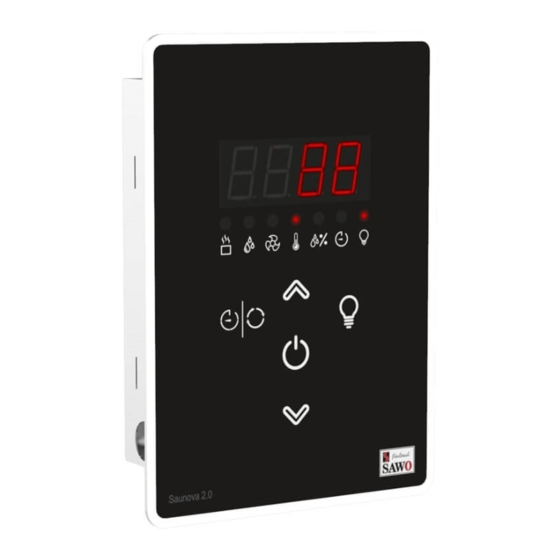
Buttons and States (Illustration) For illustrative reference only. LED Display LED Indicators Light Heater Timer Steamer (Optional) Pre-run Timer / Light Relative Humidity Mode Power (Optional) (Optional) Temperature 2. OPERATING INSTRUCTIONS 2.1 Quick Start 1. Switch the power “ON” by pressing the Power button. The set temperature will be displayed for 5 seconds followed by the actual temperature inside the sauna room. -
Page 5: Directions Of Use
2.2 Directions of use 2.2.1 Heater on Next, temperature, fan*, steamer* and Press the Power button to activate the session time (*not in all models) can be heater. The heater LED is illuminated changed if preferred. Finally long press indicating that the heater is turned on. the toggle button to confirm. -
Page 6: Setting Mode
2.2.4 Setting Mode When key lock is activated only heater on/off Press the Mode button to activate setting and cabin light functions can be used. Toggle mode. It can be used to select and adjust the button is enabled only to see actual values. If fan*, temperature, humidity* and the session other buttons are pressed, “----“... -
Page 7: Water Refill
The state for “HOT” depends on the second 2.3.3 Cabin drying sensor, the bench sensor. If it is a temperature 10 minutes after the steamer session, the sensor only, and the bench temperature in heater will automatically dry the sauna room. the sauna room is 56°C or more, the steamer The cabin drying is set to 30 minutes at 70°C;... -
Page 8: Assembly And Installation
RJ cable. 3.1 Control Unit to Heater Connection Diagram NOTE! Fig. 1 Saunova 2.0 user interface can be installed either inside or outside the sauna room. Only one user interface can be used to control the heater. INSIDE SAUNA ROOM... -
Page 9: Power Controller
3.2 Power Controller The heater is connected to the electrical network semi-stationarily with a H07RN-F The Power controller must not be located rubber cable or its equivalent. The use of inside the sauna room or in places PVC-insulated cable as a connecting cable where temperature can exceed 40°C. -
Page 10: Technical Diagram
3.4 Technical Diagram Control Unit Main Switch RJ Data Cable Separate Control Interface For Heaters more than 9 kW Fig. 5 1 1 0 1 CONTACTOR UNIT Heater >9 kW SESSION 1 2 3 SAU-UI-V2 SAU-UI-1 CONTROL SAFETY SAFETY SWITCH Max. -
Page 11: Sensors
3.5 Sensors mounted on the wall above the heater. Place One or two sensors can be connected to the the sensor 150mm from the ceiling (Fig. 6 Power Controller. The first sensor measures & 7). the temperature, it is the sensor with temperature fuse and thermistor. -
Page 12: Sensor Location With Heaters Mounted On The Floor
3.5.2 Sensor location with heaters mounted on the floor more than 200mm from the wall Top view Side view Fig. 8 Fig. 9 Air Vent See Airvent Installation Air Vent Temperature Sensor Sensor 2 (Optional) CEILING Sensor SENSOR LOCATION Air Vent Sensor See Airvent installation... -
Page 13: Fan (Optional)
3.7 Fan The fan can only be turned on and off if the fan feature is present on the control unit. The maximum power is 100W with 230 VAC. 3.8 Installation for power controller (Figure 12.) Follow the steps in the illustration below. Before installation, please read first chapter 1.1 Precautions. -
Page 14: Installation For Separate User Interface
3.9 Installation for Separate User Interface (See IIlustration) 1. Mount the separate control panel in you preferred Connect the RJ cable provided from the location. Make sure that the installation location follows control panel to the Power Controller. the min and max values in below image if the separate Insert the casing on the cut section. -
Page 15: Dip Switch
4. DIP SWITCH SESSION 4.1 DIP Switch Functions DIP Switch # Function Session time Session time Session time Combi mode Combi mode ON Combi mode OFF Slave Contactor Controller Combi heater with Combi heater with Empty 1 signal (Wm) for 2 signal (Empty &... -
Page 16: Troubleshooting
5. TROUBLESHOOTING If an error occurs, the heater will be switched off. There will be a warning beep WARNING and the code for the error will be displayed Please note, only a qualified electrician or in the control panel. maintenance personnel is allowed to make the service operations and repairs! See more details on the table below. - Page 17 Other possible problems are: • The control unit is working fine, but • The steamer is on and “dry” is displayed, the heater does not turn on. Check the even though there is plenty of water electricity supply to the heater. Check that in the tank.
- Page 18 Cabin Light (preset) 18, 24h 100W. to IEC/EN Rating 230V 1N~, 60335-2-53 100W AC1 Dimensions SAUNOVA 2.0 S types Fan without User Interface (W) 104 x (H) 147 starting capacitor. x (D) 37 Rating 230V 1N~, 0.5A Power Controller (W) 265 x (H) 245...
- Page 19 Bench Sensors Power expansion 3kW) to maximum of Bench Temperature Sensor Optional Rated Voltage 3 Phases 400V 3N~ 18kW Bench Combined Temperature - Optional Frequency 50/60Hz Humidity Sensor Switching capacity per phase Subject to change without notice. www.sawo.com | info@sawo.com...
Need help?
Do you have a question about the SAUNOVA 2.0 and is the answer not in the manual?
Questions and answers