Table of Contents
Advertisement
Quick Links
Advertisement
Table of Contents

Related Manuals for GESTRA ZK 213


Summary of Contents for GESTRA ZK 213
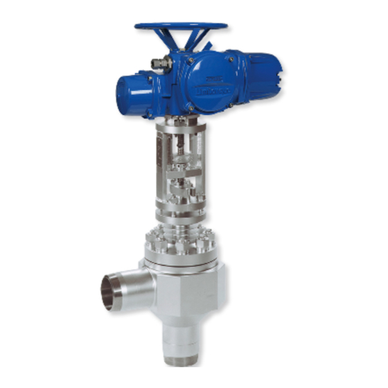
- Page 1 Control valve ZK 213 Original Installation Instructions 818449-03...
-
Page 2: Table Of Contents
Contents Foreword ............................3 Availability ............................. 3 Formatting features in the document ...................... 3 Safety ..............................4 Use for the intended purpose ......................... 4 Basic safety notes ..........................4 Qualification of personnel ........................6 Protective gear ............................6 Typographic features of warning notes ....................6 Formatting features for warnings of property damage ................ -
Page 3: Foreword
Foreword document This installation & operating manual (IOM) will help you use the control valve ZK 213 and its variants Certain text elements of this installation & operating (referred to as "equipment" in this document) safely manual feature a specific typographic design. You and efficiently for its intended purpose. -
Page 4: Safety
Basic safety notes Safety Explosion hazard Use for the intended purpose Explosion risk if equipment is used that is not The equipment is designed for controlling and suitable for the environmental conditions. When regulating the level, pressure and flowrate of fluids using the equipment in explosion risk areas in heat and process control systems. - Page 5 If the equipment is used in contaminated areas Use the equipment only if it is in proper working there is a risk of severe injuries or death caused condition. Replace any leaking stuffing box seal. by harmful substances in or on the equipment. ...
-
Page 6: Qualification Of Personnel
Qualification of personnel Typographic features of warning notes A qualified person must be acquainted with and experienced in the following: the pertinent on-site rules and regulations for DANGER preventing fire and explosions as well as industrial safety regulations Notes with the heading DANGER warn against imminent dangerous situations that ... -
Page 7: Description
Documents provided by the manufacturer of actuator Example of type designations Technical documents for position indicator (if "ZK 213-E5/40 mD" available) Angle-type design, size 5. The equipment features a hydraulic cylinder as actuator. The equipment is These documents are part of the user provided with a pressure balance device. - Page 8 Component parts Designation Designation Mechanical connection for actuator, in Direction arrow (on both sides) equipment with rotary actuator this is a Insert spindle bearing (shown here) Pressure balance device Yoke Name plate Body...
- Page 9 The yoke is fitted with the following items: Designation Designation Spindle Coupling Scale Stem Scale marking on coupling...
- Page 10 The stuffing box seal consists of the following items: Designation Designation Stuffing box flange Gland packing Stuffing box Stuffing box ring...
- Page 11 The following items are fitted inside the equipment: Designation Designation Insert (here with pressure balance) Sleeve Stem Lower main gasket Upper main gasket Collar bush...
- Page 12 Designation Designation Stem Valve plug Upper main gasket Thrust ring Pressure piece Sleeves Threaded ring Seat bushing Retaining ring...
- Page 13 The following items are available as optional extra: Designation Pressure balance device Position indicator...
-
Page 14: Task And Function
Name plate use in potentially explosive atmospheres, the discharge or prevention of possible electrostatic The following items are indicated on the name charging is the responsibility of the manufacturer or plate: owner of the system. If there is a possibility that ... - Page 15 Function During the opening process first only the stem lifts off. As a result of the reduced load the disc springs The equipment features a system of flash chambers (55) decompress. where the differential pressure is reduced in stages and the flow is split up into many partial flows. This decreases the noise level during operation and dramatically extends the service life of the equipment thanks to its high wear resistance.
-
Page 16: Storing And Transporting The Equipment
Storing and transporting the CAUTION equipment There is a risk of getting crushed by the Attention! spindle. Wear sturdy leather gloves when Equipment can be damaged if stored or working on the spindle or stem. transported improperly. Make sure that no persons are in the ... -
Page 17: Transporting The Equipment
Transporting the equipment If you do not have the sealing plugs supplied with the equipment use appropriate seal caps to seal off the DANGER connections. Risk of bruises if the equipment or For short distances (only a few metres) you can component parts fall down. -
Page 18: Mounting And Connecting The Equipment
Preparing installation Mounting and connecting the equipment Remove the transport packaging. Check the equipment for transport damage. DANGER If you detect any transport damage, please contact the manufacturer. Risk of bruises if the equipment or When supplied by the factory, the connections may component parts fall down. -
Page 19: Connecting The Equipment
Connecting the equipment The equipment is designed for installation with the stem in vertical position and the actuator mounted on top. DANGER Other installation positions are possible. Incorrectly connected equipment can result Contact the manufacturer if you want to in accidents with extremely severe injuries mount the equipment in a different or death. -
Page 20: Checking The Function
Checking the function Make sure that only qualified personnel carries out the heat treatment. Make sure that the equipment is safely mounted After the heat treatment you may insulate the and that all connections are made correctly. equipment if necessary. -
Page 21: Operating The Equipment
Operating the equipment After operation Do not work on the equipment while it is operating. DANGER DANGER If the equipment is used in contaminated areas there is a risk of severe injuries or Risk of bruises when working on the death caused by harmful substances in or equipment during operation. - Page 22 For more information on suitable protective clothing and safety gear refer to the safety data sheet of the fluid in question. DANGER Risk of bruises when working on the equipment during operation. Switch off the equipment if you have to work close to any moving equipment parts.
-
Page 23: Maintaining The Equipment
Maintaining the equipment Maintenance schedule Interval Component Activity 2 months Stem Move stem by at least one complete stroke. 3 months Stuffing box seal Visually inspect to ensure tightness. Retighten a leaky stuffing box, replace if necessary. Visually inspect the following points: ... -
Page 24: Purging The Equipment
Purging the equipment Lubricating the equipment Rinse the equipment in order to remove any dirt Attention! particles or fluid residues inside the equipment. Equipment may be damaged if unsuitable lubricant is used. DANGER Use only specified lubricants. Personnel working on pipes are exposed to safety risks and may suffer severe injuries, The following lubricants are recommended for poisoning or even loss of life. - Page 25 Rinsing equipment and pipes For details on the materials refer to the parts list. You can rinse the equipment with the same fluid Switch on the installation and rinse the pipes. that is used during normal operation. You can also ...
-
Page 26: Disassembling The Equipment
Disassembling the equipment Preparing the equipment for disassembly You have to disassemble the equipment if you want DANGER Personnel working on pipes are exposed to rinse the pipes and the equipment safety risks and may suffer severe injuries, service component parts poisoning or even loss of life. - Page 27 The space required for disassembling and DANGER re-assembling the equipment depends on the optional extras and the type of Risk of bruises if the equipment or actuator. component parts fall down. For more information on the required service space see the attached drawings. ...
- Page 28 Removing actuator parts Some equipment is fitted with a position indicator. The position indicator comes If the equipment is fitted with an actuator first with a separate installation & operating remove the actuator. manual (IOM). Disconnect the actuator as described in the operating manual for the actuator.
- Page 29 You can now remove the mechanical connection for Remove the two hexagon head bolts (35). the actuator. The following drawing shows the For equipment with an electrical rotating motor, you equipment with actuator bearing for an must remove the spindle bearing and spindle. electric rotary actuator.
- Page 30 Removing the bonnet Removing the insert from equipment without pressure balance Remove the eight cap nuts (36). Connect the noose strap of a sufficiently strong The procedure for equipment with lifting gear to the bonnet flange. pressure balance is described on page ...
- Page 31 Connect the noose strap of a sufficiently strong lifting gear to the stuffing box flange (13). Lift the insert (6) off the equipment. Take the stem (12) out of the equipment. Take the upper main gasket (17) out of the equipment.
- Page 32 Removing the insert from equipment with pressure balance The procedure for equipment without pressure balance is described on page To remove the packing rings proceed as follows: Attention! Excessive loosening can damage the stuffing box packing. Loosen the nuts of the stuffing box bolts only until the resistance felt ceases.
- Page 33 Connect the noose strap of a sufficiently strong Removing the thrust ring lifting gear to the stuffing box flange (13). To remove the thrust ring use a special removal Lift the insert (6) off the equipment. support. The removal support comprises: ...
- Page 34 Place the support frame with the rods above the upper edge of the body. The bores in the rods must be exactly above the threaded holes (42) in the thrust ring (25). Screw the two threaded rods (41) through the bores in the rods into the threaded holes (42) in the thrust ring.
- Page 35 Removing the seat bushing Once the threaded rods are firmly attached to the seat bushing screw the two nuts (40) above To remove the seat bushing use a special removal the rods handtight. support. The removal support comprises: a support frame of sufficient height (extending beyond the upper edge of the equipment) ...
- Page 36 To remove the seat bushing from the body other case the stuffing box can remain attached to tighten the two nuts of the removal support the insert in order to avoid damage to the packing evenly. rings. Tighten the nuts until the seat bushing is completely lifted off the body.
- Page 37 Lift the packing rings of the stuffing box (15) off Attention! the insert. In equipment with a connection for sealing The packing rings may get damaged. fluid the medium packing ring is replaced Make sure you do not damage the by a grooved ring.
- Page 38 Lift the packing rings of the stuffing box (15) off Removing the pressure balance element the insert. You can now take the pressure balance device out Lift the stuffing box ring (16) off the insert. of the insert. For this purpose proceed as follows: ...
- Page 39 Pull the small segment (54) out of the support Press the valve plug (24) into the stem (12) and ring (53). hold it there. To remove the support ring pull it out of the The disc springs are compressed. The pressure on sleeve of the pressure balance device (7).
-
Page 40: Assembling The Equipment
Pull the valve plug (24) downwards off the stem. Attention! Take the pressure piece (21) off the valve plug. Take the disc springs (55) out of the valve plug. Equipment may leak if the gaskets are damaged. ... - Page 41 Fitting the valve plug Put the bore in the stem (12) onto the valve plug (24). The number and position of the disc springs is shown and described in the supplied technical documents. Insert the disc springs (55) into the hole in the valve plug (24) (1.).
- Page 42 Insert the threaded ring (22) into the gap Insert the retaining ring (23) into the gap between the stem and the valve plug. between the stem and the valve plug. Put the claw tool (56) into the groove in the ...
- Page 43 Fitting the collar bush Use a suitable lifting device to put the seat bushing (27) onto the body. Normally you do not have to remove the collar bush from the body. For the installation proceed in reverse order of the removing procedure.
- Page 44 Fitting the sleeves and stem Attention! Equipment may get damaged if the sleeves are tilted or skewed when fitted. Make sure that the sleeves are not tilted or skewed when put into the body. Use a suitable mounting support or lifting device.
- Page 45 Remove the mounting support and keep it for Compressing lower main gasket future use. Attention! Put the stem (12) into the sleeve. Equipment may not work properly or get damaged if screws, nuts or bolts are tightened with the wrong torques. ...
- Page 46 Apply MoS grease to the threads of the stud bolts (37) and the cap nuts (36). Apply MoS grease to the seating surfaces of the cap nuts. Screw the stud bolts into the bores of the body. ...
- Page 47 Take the insert off the stem. You do not have to remove the stud bolts from the body. In the following drawings the stud bolts are not shown for reasons of clarity. Attaching pressure balance element Put the sleeve (50) of the pressure balance device into the insert (6).
- Page 48 Put the retaining ring (52) into the insert. Put the support ring (53) into the insert. Insert the small segment (54) into the support ring (53). To mount the stuffing box packing do not tighten the bolts any more. Attention! ...
- Page 49 Fitting the insert Mounting the gland packing The mounting procedure for the insert is The mounting procedure for the stuffing the same for equipment with and box packing is the same for equipment equipment without pressure balance. with and equipment without pressure The following drawing shows the balance.
- Page 50 Put the stuffing box ring (16) into the stuffing Attention! box. Put the packing rings (15) into the stuffing box. Equipment may not work properly or get damaged if screws, nuts or bolts are In equipment with a connection for sealing tightened with the wrong torques.
- Page 51 Put the stuffing box (14) in place. Attention! Apply MoS grease to the threads of the stud bolts (45) and nuts (44). Equipment may not work properly or get Screw the stud bolts into the threaded bores of damaged if screws, nuts or bolts are the insert.
- Page 52 Mounting the bonnet Attention! Equipment may not work properly or get damaged if screws, nuts or bolts are tightened with the wrong torques. Apply the torques indicated in the parts list when tightening screws, nuts and bolts. The tightening torques for your equipment are indicated in the parts list.
- Page 53 Installing the actuator The work required for mounting the actuator depends on the actuator type. Proceed in reverse order of disassembling the equipment. The following drawing shows the equipment for a rotary actuator. Attention! Stem may get damaged if the spindle protrudes too much.
- Page 54 Connect the actuator properly to its power Attention! supply. Equipment may not work properly or get damaged if screws, nuts or bolts are tightened with the wrong torques. Apply the torques indicated in the parts list when tightening screws, nuts and bolts.
- Page 55 Mounting the coupling Attention! Malfunctions may occur if the coupling is not properly aligned with the stem. Make sure that the marking on the stem and the scale are properly aligned. Make sure that there is adequate spacing between the coupling and the stem.
- Page 56 Align the central hole in the halves of the coupling with the hole in the spindle. Connect the coupling and spindle with the hexagon head bolt (29). Hand-tighten the nut (30) on the hexagon head bolt (29). Attention! Equipment may not work properly or get damaged if screws, nuts or bolts are...
-
Page 57: Servicing The Equipment And Installing Spare Parts
Servicing the equipment and installing spare parts You may exchange the following component parts in case of wear or damage: The material specification and stock code numbers of the component parts are indicated in the supplied parts list. Disassemble the equipment as described from page 26 onwards. -
Page 58: Troubleshooting
Troubleshooting Problem Cause Remedy The stem moves with difficulty Malfunction in actuator. Follow the instructions in the operating or jerky. manual for the actuator. The actuator switches off Malfunction in controller. Follow the instructions in the operating automatically. manual for the controller. The stuffing box packing Loosen the nuts of the stuffing box affects the stem lift. -
Page 59: Putting The Equipment Out Of Operation
Putting the equipment out of Attention! operation Environmental damage may be caused by Removing harmful substances poisonous fluid residues. Before disposing of the equipment DANGER make sure that it is clean and free of fluid residues. If the equipment is used in contaminated ... - Page 60 DANGER WARNING Risk of bruises if the equipment or Risk of severe injuries or death if the component parts fall down. actuator is not removed correctly. Always wear protective gear when Before working on the actuator cut off working on the equipment.
-
Page 61: Disposing Of The Equipment
Disposing of the equipment Attention! Environmental damage may be caused by poisonous fluid residues. Before disposing of the equipment make sure that it is clean and free of fluid residues. For the disposal of all materials observe the pertinent legal regulations concerning waste disposal. -
Page 62: Manufacturer's Declaration
European Directives in our Declaration of Conformity or our Declaration of Incorporation. To request the valid Declaration of Conformity or Declaration of Incorporation, please contact: GESTRA AG Münchener Straße 77 28215 Bremen Germany Telefon +49 421 3503-0... - Page 64 Agencies all over the world: www.gestra.de GESTRA AG Münchener Straße 77 28215 Bremen Germany Telefon +49 421 3503-0 Telefax +49 421 3503-393 E-Mail info@de.gestra.com www.gestra.de 818449-03/07-2017 kx_mm (808557-03) © GESTRA AG Bremen Printed in Germany...
Need help?
Do you have a question about the ZK 213 and is the answer not in the manual?
Questions and answers