
Related Manuals for GESTRA BB 1 Series


Summary of Contents for GESTRA BB 1 Series
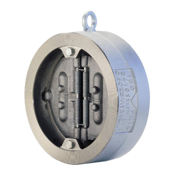
- Page 1 Double Swing Check Valve BB 1 BB 2 BB 3 Original Installation Instructions 819649-00...
-
Page 2: Table Of Contents
Contents Foreword ............................3 Availability ............................. 3 Formatting features in the document ...................... 3 Safety ..............................3 Use for the intended purpose ......................... 3 Basic safety notes ..........................4 Typographic features of warning notes ....................5 Formatting features for warnings of property damage ................5 Description ............................ -
Page 3: Foreword
Formatting features in the Foreword document This installation & operating manual will help you use the following types of equipment safely and Certain text elements of this installation & operating efficiently for their intended purpose. manual feature a specific typographic design. You ... -
Page 4: Basic Safety Notes
Basic safety notes If the admissible temperature and pressure limits are exceeded the equipment may be destroyed and hot or pressurized fluid may Risk of severe injuries escape. Make sure that the equipment is only The equipment is under pressure during operated within the admissible service range operation and may be hot. -
Page 5: Typographic Features Of Warning Notes
Typographic features of warning Equipment series and optional extras Equipment types BB 1 and BB 2 differ from each notes other in the way the hinge pins for the discs in the body are attached. DANGER Various types of equipment are available which Notes with the heading DANGER warn differ from each other in the following: against imminent dangerous situations that... - Page 6 The equipment can feature a seat made from: Metal-to-metal EPDM FPM (FKM) NBR PTFE The following springs are available. Code number/letter Application 7 WA Spring for 7 mbar opening pressure, for horizontal installation 7 WAI Inconel spring for 7 mbar opening pressure, for horizontal installation and...
- Page 7 Equipment specification Units BB 1 and BB 3 DN 50–125, DN 450–500 In these units, the bearing pins of the swing discs are mounted on bearings in the body. No. Designation No. Designation Seal screw with gasket Seal Eye bolt 2 pairs of springs Name plate with flow direction arrow Plates...
- Page 8 Units BB 2 and BB 3, DN 150–400 In these units, the bearing pins of the swing discs are mounted on bearing blocks in the body. No. Designation No. Designation Eye bolt Plates Name plate with flow direction arrow Hinge pins Body 10 Plate support for plates with threaded bolt Seal...
- Page 9 Equipment with damper Equipment with optional damper and a corresponding bore in the equipment is available. Designation Damper with gasket For fitting the damper the body of the equipment must be provided with a bore. The standard body does not have such a bore and can therefore not be equipped with a damper.
-
Page 10: Application Of European Directives
ATEX Directive Name plate The equipment does not have its own potential The indications on the name plates vary according ignition source and is not subject to this directive to the equipment type. (see "Manufacturer's Declaration" section). The name plate may specify the following: ... -
Page 11: End Connections
Storing the equipment Dampers Optional dampers can be used to influence the Please observe the following items when storing closing characteristics. A dampening medium slows the equipment: down the plate movement during the last 15° of the closing path. As a result the plates close more ... -
Page 12: Mounting And Connecting The Equipment
Mounting the equipment Mounting and connecting the equipment Attention Equipment will be damaged if the end Preparing installation connections are undersized. Take the equipment out of the transport Make sure that the connections are packaging. strong and rigid enough to support the ... - Page 13 A straight distanceof at least five times the nominal Installing the equipment with vertical pipe diameter for stabilizing the flow pattern must direction of flow be left upstream of the equipment. DANGER Attention Incorrectly connected equipment can result in accidents with extremely severe injuries Malfunctions may occur if the stabilizing or death.
- Page 14 If the equipment is installed in a vertical pipe the Put a commercially available gasket that is flow arrow must point upwards. suitable for the pipe onto the lower flange. Put the equipment onto the gasket. Put a commercially available gasket that is suitable for the pipe onto the equipment.
- Page 15 Installing the equipment with horizontal direction of flow DANGER Incorrectly connected equipment can result in accidents with extremely severe injuries or death. Make sure that only specialist personnel connect the equipment to the pipe. Make sure that the direction of flow in the pipe matches the flow direction arrow on the equipment.
-
Page 16: Operation
Maintaining the equipment Operation The equipment is maintenance-free. Do not work on the equipment while it is operating. After operation DANGER If fluid escapes personnel may suffer severe injuries, poisoning or even loss of life. After working on the equipment make sure that all connections and valves are tight. -
Page 17: Servicing The Equipment And Installing Spare Parts
Servicing the equipment and installing spare parts You may exchange the following component parts in case of wear or damage: Order small quantities of seat gasket (6) from a specialist retailer Spring (7), complete, with tension plate Spring (7) stock codes Seal (6) stock code Stock code Stock code #... - Page 18 Removing the equipment Removing springs from BB 1 and BB 3, DN 50–125, DN 450–500 To exchange the spring or the gasket you have to remove the equipment. To mount and remove the spring you need the following tools: You may not be able to move heavy ...
- Page 19 Remove the cover. DANGER Take the four springs (7) out of the body (1.). Risk of bruises if the equipment or Spread the plates slightly apart (2.). component parts fall down. Use suitable lifting gear when moving or lifting the equipment and/or component parts.
- Page 20 Lift the two plates (8) out of the body (1.). Lift the plates or angle brackets (5) out of the body (2.). WARNING The springs are preloaded and their tension can cause injuries. Always wear safety goggles when replacing the springs.
- Page 21 DANGER WARNING Risk of bruises if the equipment or The springs are preloaded and their component parts fall down. tension can cause injuries. Use suitable lifting gear when moving Always wear safety goggles when or lifting the equipment and/or replacing the springs.
- Page 22 Exchanging the gasket DANGER The area of application of gaskets depends Risk of bruises if the equipment or on the medium and temperature. component parts fall down. Some types are fitted with metal seats. Use suitable lifting gear when moving Gaskets cannot be replaced in these or lifting the equipment and/or models.
- Page 23 Pull the second hinge pin (9) out of the body. WARNING The springs are preloaded and their tension can cause injuries. Always wear safety goggles when replacing the springs. Mount or remove one spring after the other. ...
- Page 24 Make sure that the plates fully rest against the Tightening torque [Nm] for austenitic steel body seat sealing plugs BB 11 BB 12, BB 14 BB 17, BB 19 WARNING BB 15, BB 16, BB 18 BB 32, BB 34, The springs are preloaded and their BB 35, BB 36 tension can cause injuries.
- Page 25 Installing springs in BB 2 and BB 3, DN 150– Push the two hinge pins (9) through the springs (1.). Put the two plate supports (10) as shown onto WARNING the ends of the hinge pins (2.). The springs are preloaded and their tension can cause injuries.
- Page 26 Remove the eye bolts and keep them for future To mount the plates in large equipment use suitable use. lifting gear. Attach the lifting gear to the plates as Turn the plates until the bores in the plate follows: supports are underneath the stops (1.).
- Page 27 Tightening torque [Nm] for threaded bolts on BB 21, BB 22, BB 24, BB 32, BB 34, BB 35 and BB 36 Steel threaded bolt Bronze threaded bolt Uncoated body Coated body Uncoated body Coated body Carefully pull the tension plates (14) off the springs.
-
Page 28: Troubleshooting
Troubleshooting Problem Cause Remedy Loud noise The equipment is operating in the Raise the volume flow by increasing the unstable range of the volume flow pump capacity. with the swing disk oscillating. Install the equipment at a different position. The distance between the Increase the distance of the equipment equipment and the pump is too so that a stabilized flow is provided. -
Page 29: Putting The Equipment Out Of Operation
Remove all residues from the equipment. For the disposal of all residues observe the Putting the equipment out of pertinent legal regulations concerning waste operation disposal. Removing harmful substances Removing the equipment DANGER DANGER If the equipment is used in contaminated Personnel working on pipes are exposed to areas there is a risk of severe injuries or safety risks and may suffer severe injuries,... -
Page 30: Re-Using Equipment After Storage
Disposing of the equipment Attention! Caution Excessive loads may damage the closing dampers. Environmental damage may be caused by Use the eye bolt for fixing lifting gear. poisonous fluid residues. Do not stress the closing dampers. Before disposing of the equipment make sure that it is clean and free of ... - Page 31 Materials in the grey cast iron version (BB.. G, GS, GK) Component BB ...G BB ...GK BB ...GS Body 5.1301 5.1301 5.1301 (EN-JL 1040) (EN-JL 1040) (EN-JL 1040) Anti-corrosion coating on body – Rilsan Hard rubber Inner parts Stainless Bronze Bronze Stainless steel...
- Page 32 The seals can be made from the following materials: Type Material EPDM Ethylene propylene diene rubber FPM (FKM) Fluoro rubber (e. g. Viton) Acrylonitrile butadiene rubber (e. g. Perbunan) PTFE FPM, FEP coated...
-
Page 33: Technical Data
Technical data Dimensions and weights BB 11 G, PN 6 Dimensions [mm] Weight [kg] 1000 1,093 BB 12 G, PN 10 Dimensions [mm] Weight [kg] 1,020 1000 1,127... - Page 34 BB 14 G, PN 16 Dimensions [mm] Weight [kg] [inches] 1,014 1000 1,131...
- Page 35 BB 17, PN 63 Dimensions [mm] Weight [kg] [inches] Length as per ASME (API 594) BB 17 A only Non-standard length.
- Page 36 BB 18, PN 100/CLASS 600 Dimensions [mm] Weight [inches] [kg] PN 100 CL 600 22.5 Length as per ASME (API 594) BB 18 A only Non-standard length.
- Page 37 BB 19, PN 160, CLASS 900 Dimensions [mm] Weight [inches] [kg] PN 160 CLASS 900 Length as per ASME (API 594) BB 21 G, PN 6 Dimensions [mm] Weight [kg] 18.5 62.5 80.5...
- Page 38 BB 22 G, PN 10 Dimensions [mm] Weight [kg] 13.5 BB 24 G, PN 16 Dimensions [mm] Weight [kg] [inches] 13.5...
- Page 39 EN series BB 3 ... short as per DIN EN 558, basic series 16 Dimensions [mm] Weight [kg] 10/16/25/40 10/16/25/40 10/16/25/40 10/16 25/40 10/16 25/40 10/16 11.0 25/40 11.5 10/16 19.0 20.0 21.0 10/16 34.0 37.0 40.0 44.0 45.5 57.0 61.5 66.0 67.5...
- Page 40 Dimensions [mm] Weight [kg] 90.5 93.5 112.0 124.0 106.0 110.0 121.0 128.0 130.0 136.0 148.0 152.0...
- Page 41 ASME series BB 3 ... with length as per API 594 NPS [inches]/DN CLASS Dimensions [mm] Weight [kg] 2/50 2½/65 3/80 4/100 5/125 11.0 13.0 6/150 11.5 16.0 8/200 19.5 24.5 10/250 36.0 44.0 12/300 58.5 61.0 14/350 78.5 88.0 16/400 110.0 120.0...
- Page 42 NPS [inches]/DN CLASS Dimensions [mm] Weight [kg] 18/450 116.0 157.0 20/500 142.0 192.0 Non-standard length...
- Page 43 ASME series BB 3 ... short as per DIN EN 588, basic series 16 NPS [inches]/DN CLASS Dimensions [mm] Weight [kg] 6/150 15.5 19.0 8/200 27.5 31.0 10/250 46.0 60.0 12/300 80.0 82.5 14/350 99.0 123.5 16/400 134.5 164.0 18/450 152.0 207.0 20/500...
- Page 44 Weights and dimensions for equipment with dampers A [mm] B [mm] 1.110 1.220 1.325 Weight [kg] The specifications refer to equipment PN 16. For information on other types please contact the manufacturer.
-
Page 45: Pressure & Temperature Ratings
Pressure & temperature ratings For the max. flowrate as a function of the differential pressure see the capacity chart in the data sheet. EN series Admissible maximum pressure [bar] for equipment with grey cast iron body Type Temperature [°C] -10/20 BB 11, BB 21 BB 12, BB 22 BB 14, BB 24... - Page 46 Admissible maximum pressure [bar] for equipment with stainless steel body Type Temperature [°C] -196/ 525 550 BB 32 50-500 BB 34 50-500 15.2 12.1 10.3 9.4 BB 35 50-500 23.8 18.9 16.1 14.7 14.1 14.0 13.9 13.1 12.9 BB 36 50-500 38.1 30.2 25.8 23.5 22.6...
- Page 47 ASME series Admissible maximum pressure [bar] for equipment with steel body Type Class Temperature [°C] -29/ BB 35 19.6 17.7 13.8 12.1 10.2 BB 36 51.1 46.6 43.8 41.9 39.8 37.6 34.7 28.8 BB 18 102.1 93.2 87.6 83.9 79.6 75.1 69.4 57.5...
- Page 48 Limiting conditions for equipment with optional extras Limiting conditions for equipment with anti- corrosion lining The admissible limiting conditions for equipment with anti-corrosion lining are indicated in the following tables: Coating Temperature range [°C] Rilsan –10 to +90 Hard rubber –10 to +90 Limiting conditions for equipment with dampers The admissible limiting conditions for equipment...
-
Page 49: Manufacturer's Declaration
Assessment according to European rules refer to our Declaration of Conformity or our Declaration by Manufacturer. To download the current Declaration of Conformity or Declaration by Manufacturer go to www.gestra.com/documents or contact: GESTRA AG Münchener Straße 77 28215 Bremen Germany... - Page 52 Agencies all over the world: www.gestra.de GESTRA AG Münchener Strasse 77 28215 Bremen Germany Phone +49 421 3503-0 +49 421 3503-393 e-mail info@de.gestra.com www.gestra.com 819649-00/04-2019 kx_mm (808997-00) © GESTRA AG Bremen Printed in Germany...
Need help?
Do you have a question about the BB 1 Series and is the answer not in the manual?
Questions and answers