
Subscribe to Our Youtube Channel
Related Manuals for GESTRA CB 26


Summary of Contents for GESTRA CB 26
- Page 1 GESTRA GESTRA Steam Systems CB 1... CB 2... Installation Instructions 810707-02 Swing Flap Non-Return Valves CB 1..., CB 2...
-
Page 2: Table Of Contents
CB 1..............................15 CB 2... Replace springs / O-ring ....................16 – 17 Tools ..............................17 Spare Parts Spare parts list CB 24 S ........................18 Spare parts list CB 26, CB 26 S ......................19 Annex Declaration of conformity ........................20... - Page 3 Parts Drawing CB 1... Fig. 1...
- Page 4 Parts Drawing CB 2... Fig. 2...
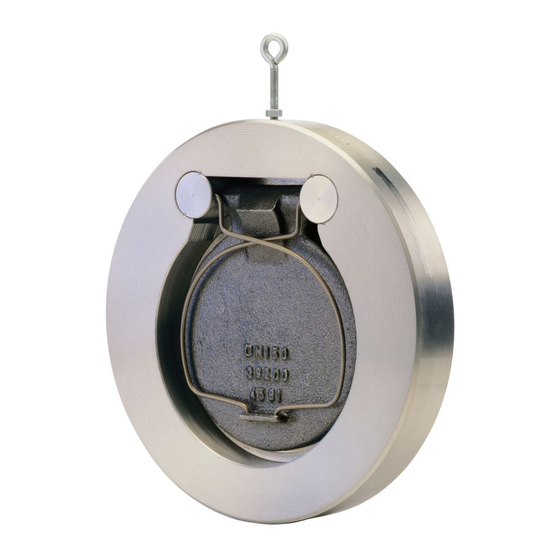
- Page 5 Eye bolt Lock nut Centering ring Type designation (on name plate or impressed on valve body) Body O-ring Disc Spring...
- Page 6 Pressure Drop Chart CB 1... Partial opening Full opening = instable range = stable range Pressure drop ∆p [bar] Fig. 3 ρ The curves given in the chart are valid for V ˙ = V ˙ · water at 20 °C. To read the pressure drop for 1000 other fluids the equivalent water volume V ˙...
- Page 7 Pressure Drop Chart CB 2... Partial opening Full opening = instable range = stable range Pressure drop ∆p [bar] Fig. 4 ρ The curves given in the chart are valid for V ˙ = V ˙ · water at 20 °C. To read the pressure drop for 1000 other fluids the equivalent water volume V ˙...
-
Page 8: Important Notes
Important Notes Usage for the intended purpose The swing flap non-return valves CB 1.../CB 2... ensure unidirectional flow in pipes by preventing a backflow of liquids or gases. Use this equipment only within the specified pressure and temperature ratings and check corrosion resistance and chemical suitability for the application in question. -
Page 9: Ratings Pursuant To Article 9 Of The Ped
Important Notes – continued – Ratings pursuant to article 9 of the PED Liquid Fluid group CB 14 CB 24 S CB 26 CB 26 A Exception pursuant to Category article 3.3 Nominal size CB 14 50 –80 100 –200 250–300... -
Page 10: Explanatory Notes
1 Swing flap non-return valve CB 26 1 Installation manual CB 26 A 1 Swing flap non-return valve CB 26 A 1 Installation manual Description The CB 1.../CB 2... are very compact swing flap non-return valves used to prevent the backflow of fluids. -
Page 11: Technical Data
[bar] 16 6–16 pressure *) When used for its intended purpose. With springs made of bronze up to max. 90 °C. Pressure/Temperature Ratings*) CB 26, steel down to –10 °C at nominal pressure DN 50 – 200 Temperature [°C] 20 Pressure DN 50 –200... -
Page 12: Name Plate / Marking
Specification (plate): CB 26, DN 50-200 to EN 19 Fig. 10 Specification (plate): CB 26 A, DN 50-200 to EN 19 Fig. 11 Specification (plate): CB 24 S, CB 26, CB 26 A, DN 250-300 to EN 19 Fig. 12... -
Page 13: Installation
Installation Note When the volume flow reaches the instable range (see Pressure Drop Chart) during operation clatter may occur which gives rise to wear on the oscillating flap. Fig. 3, Fig. 4 Do not install swing flap non-return valves in vertical downward flow lines. CB 1..., CB 2... -
Page 14: Installation Notes
Installation – continued – incorrect correct Fig. 13 Fig. 14 optimum with pump Fig. 15 Fig. 16... -
Page 15: Commissioning
Maintenance CB 1... GESTRA Swing flap non-return valves CB 1... do not require special maintenance. The swing flap non-return valves have to be replaced in case of damage or considerable wear. Parts subject to wear and spare parts are not available. -
Page 16: Cb 2
Maintenance – continued – GESTRA Swing flap non-return valves CB 2... do not require special maintenance. However, in certain cases it may be necessary to replace the springs or O-rings. Danger Note that springs are preloaded which means that they can jump out of the valve body when the valve is being installed or removed. -
Page 17: Tools
Maintenance – continued – CB 2... Replace springs / O-ring – continued – Insert left and right spring into the support. Check smooth operation of the flap. Install swing flap non-return valve in line. Tools Combination pliers 180 mm, DIN 5244 Aligning punch, 80 mm... -
Page 18: Spare Parts
Spare Parts Spare Parts List CB 24 S Stock code Stock code Stock code Stock code Item O-ring EPDM O-ring FPM O-ring NBR Spring 039276 037556 038624 038626 031443 033910 038633 038635 031753 033911 038642 038644 031493 033912 038651 038654 031769 033913 038662... -
Page 19: Spare Parts List Cb 26, Cb 26 S
Spare Parts – continued – Spare Parts List CB 26, CB 26 A Stock code Stock code Stock code Stock code Item O-ring EPDM O-ring FPM O-ring NBR Spring 039276 037556 175843 039294 031443 033910 703368 039295 031753 033911 173844... -
Page 20: Annex
Applied conformity assessment procedure as described in Annex III for CB 24 and CB 24 S: Module A1 Applied conformity assessment procedure as described in Annex III for CB 26 and CB 26 A: Module H - verified by the Notified Body (Registration No.0525). - Page 21 For your notes...
- Page 22 For your notes...
- Page 23 For your notes...
- Page 24 Postfach 10 54 60, D-28054 Bremen Münchener Str. 77, D-28215 Bremen Telefon +49 (0) 421 35 03 - 0 Telefax +49 (0) 421 35 03 - 393 E-Mail gestra.ag@flowserve.com Internet www.gestra.de 810707-02/604cm · © 2001 GESTRA AG · Bremen · Printed in Germany...
Need help?
Do you have a question about the CB 26 and is the answer not in the manual?
Questions and answers