
Related Manuals for GESTRA BW 31A


Summary of Contents for GESTRA BW 31A
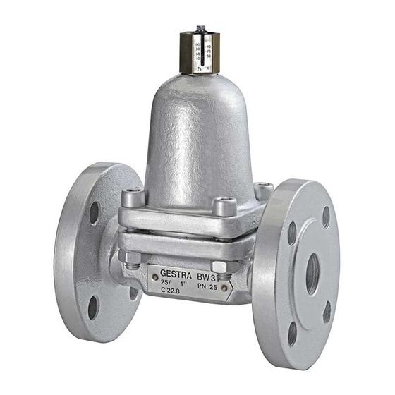
- Page 1 Return-Temperature Control Valve BW 31 BW 31A Original Installation Instructions 819026-01...
-
Page 2: Table Of Contents
Contents Preface..............................3 Availability ............................. 3 Text layout ............................3 Safety ..............................3 Usage for the intended purposeand obvious misuse or abuse ..............3 Basic safety notes ..........................4 Typographic features of safety notes ....................... 5 Description ............................5 Scope of supply and equipment specification ..................5 Purpose and function .......................... -
Page 3: Preface
Equipment type BW 31A is only designed for good professional practice. use with hot oil. Correct use includes compliance with the Availability instructions given in this installation &... -
Page 4: Basic Safety Notes
Basic safety notes Risk of minor injuries Sharp edges on internals present the danger of Risk of severe injuries cuts to hands. Always wear industrial gloves when servicing the equipment. The equipment is under pressure and hot during operation. -
Page 5: Typographic Features Of Safety Notes
Typographic features of safety Description notes Scope of supply and equipment Danger note specification DANGER Scope of supply Our equipment is delivered packed and ready for Notes with the heading DANGER warn assembly. against imminent dangerous situations that can lead to death or serious injuries. Equipment specification The equipment consists of the following main WARNING... - Page 6 Designation Designation Nuts (only DN40) Thermovit regulator Cover Socket-head bolts Distance sleeve (only DN40) Name plate with flow direction arrow Adjustment nut Body Bimetallic regulator plates Gaskets (2 for DN40) An external setting device is available as optional without having to remove the cover. There are extra.
- Page 7 Nominal pressure Temperature scale Differential pressure Forked adjustment piece Temperature External setting device for BW 31A Flow arrow The name plate is pointed on one side. This serves as an additional indication of the flow direction.
-
Page 8: Purpose And Function
Storing and transporting the ATEX Directive equipment The equipment does not have its own potential ignition source and is not subject to this directive (see "Manufacturer's Declaration" section). Attention! When installed, static electricity may arise between the equipment and the connected system. Equipment can be damaged if stored or When used in potentially explosive atmospheres, transported improperly. -
Page 9: Transporting The Equipment
Transporting the equipment DANGER Meet the requirements for storage also when transporting the equipment. Personnel working on pipes are exposed to Prior to transport seal off connections with safety risks and may suffer severe injuries, sealing plugs. burns, poisoning or even loss of life. ... -
Page 10: Adjusting The Closing Temperature
Make sure that the equipment is safely mounted and that all connections are made correctly. The are different procedures for BW 31 and BW 31A. To remove residues from the pipes and the equipment after installation purge the Adjusting the closing temperature for BW 31 pipes with the fluid to be used. - Page 11 Repeat the setting procedure if the return temperature does not meet the set value. Adjusting the closing temperature for BW 31A The closing temperature is set via the slide lift. When the equipment is delivered, the following temperature settings as a function of nominal size...
-
Page 12: Adjusting The Closing Temperating Without External Setting Device
To lower the closing temperature turn the Repeat the setting procedure if the return adjustment stem (14) clockwise. temperature does not meet the set value. The following table indicates the closing temperature that will be set by giving the Adjusting the closing temperating adjustment stem a certain number of full turns. - Page 13 Ascertaining the set value for BW 31 DANGER The number of plate pairs used in the Thermovit regulator depends on the required closing Personnel working on pipes are exposed to temperature. safety risks and may suffer severe injuries, burns, poisoning or even loss of life. Closing temperature Number of plate pairs DN15 ...
- Page 14 The set value is based on ambient temperatures of Closing temperature Set value [mm] 18 – 21 °C. If the ambient temperature is higher or [°C] DN15 DN20, DN40 lower use the following table to adjust the set value. DN25 22.4 23.6 41.8...
- Page 15 Ascertaining the set value for BW 31A Closing temperature Set value [mm] The set value is based on ambient temperatures of [°C] 18 – 21 °C. If the ambient temperature is higher or DN15 DN20, DN40 lower use the following table to adjust the set value.
- Page 16 Use the Thermag nut (4) to adjust the desired set value. The Thermag nut used in equipment DN 15 to DN 25 is a nut type M6 and in equipment DN 40 a nut M8. It is locked and sealed with Loctite 222. ...
-
Page 17: After Operation
After operation Attention! DANGER Malfunctions due to dirt deposits on Thermovit regulator. If the equipment is used in contaminated Remove Thermovit regulator before areas there is a risk of severe injuries or rinsing the equipment. death caused by harmful substances in or on the equipment. - Page 18 Removing cover Fasten screws / nuts and bolts with the following tightening torque: The cover of equipment DN 15 to DN 25 is fixed in DN15 to DN25: 35 Nm place by means of four 8 mm socket-head cap ...
-
Page 19: Maintaining Equipment
Maintaining equipment Mounting Thermovit regulator after purging Remove the cover as described on page 18. The equipment is maintenance-free. Attention! Servicing equipment You may exchange the following component parts Malfunctions due to inadvertent in case of wear or damage: misadjustment of Thermovit regulator. - Page 20 Spare parts for BW31 without external setting device Designation Temperature Qty. Stock code # range [°C] Thermovit regulator, complete 20–90 184726 60–130 031884 20, 25 20–90 184560 40–115 004339 20–65 184544 50–110 004342 Gasket 15, 20, 25 560493 20** 375699 * one piece required ** two pieces required...
- Page 21 Spare parts for BW31A without external setting device Designation Temperature Qty. Stock code # range [°C] Thermovit regulator, complete 60–120 377776 120–270 184807 20, 25 30–120 184880 100–280 184731 30–80 184857 100–270 184808 Gasket 15, 20, 25 560493 20** 375699 * one piece required ** two pieces required...
- Page 22 Spare parts for BW31 with external setting device Designation Temperature Qty. Stock code # range [°C] Thermovit regulator, complete 20–110 184550 60–130 031896 20, 25 20–90 036933 40–115 004340 20–75 038972 50–110 004343 Gasket 15, 20, 25 560493 20** 375699 External setting device 20–120 184899...
- Page 23 Spare parts for BW31A with external setting device Designation Temperature Qty. Stock code # range [°C] Thermovit regulator, complete 60–160 184631 90–270 004010 20, 25 30–170 184937 70–270 004022 25–85 184661 70–270 004025 Gasket 15, 20, 25 560493 20** 375699 External setting device 184902 20, 25...
- Page 24 Exchanging Thermovit regulator Unscrew the external setting device from the cover. Only the complete Thermovit regulator unit can be exchanged. Remove the cover as described on page 18. Unscrew the Thermovit regulator off the body as described on page 18. ...
- Page 25 Put a new gasket onto the external setting Fasten the external setting device with the device. following tightening torque: (step 2.) DN15 to DN25: 90 Nm Attention! DN40: 140 Nm. Equipment may be damaged if the external setting device is tilted or skewed when fitted.
-
Page 26: Troubleshooting
Troubleshooting Fault Cause Remedy Equipment does not control The Thermovit regulator is Remove Thermovit regulator. correctly. contaminated. Rinse equipment. Rinse Thermovit regulator. Mount Thermovit regulator. The Thermovit regulator is Discard and replace Thermovit regulator. damaged. The outlet temperature exceeds The leak passage is too high. Change the settings of the installation or the adjusted closing The design data for sizing the... -
Page 27: Putting Equipment Out Of Operation
Putting equipment out of Attention! operation Environmental damage may be caused by Removing harmful substances poisonous fluid residues. Before disposing of the equipment DANGER make sure that it is clean and free of fluid residues. If the equipment is used in contaminated ... -
Page 28: Re-Using Equipment After Storage
BW31 specified. Seal ring for external EPDM setting device BW31 Gasket for external 1.4301 N – setting device BW31 and BW 31A External setting 1.4571 AISI 316 Ti device BW31A Stuffing box BW31A Graphite... -
Page 29: Technical Data
Space required for servicing Width of cover flange[mm] Weight [kg] 4.4 5.3 5.7 12 4.4 5.3 5.7 * DN40: PN25 ** Class 300: 230 mm *** External setting device BW 31A Flanges to Flanges to ASME Screwed Butt-weld EN PN40* Class 150/Class 300... -
Page 30: Pressure & Temperature Ratings
50–110 BW 31 with external setting device 60–130 40–115 50–110 BW 31 with special external setting device 20–110 20–90 20–75 BW 31A, BW 31A with external setting device 90–270 70–270 BW 31A with special external setting device 60–160 30–170 25–85... -
Page 31: Manufacturer's Declaration
Assessment according to European rules refer to our Declaration of Conformity or our Declaration by Manufacturer. To download the current Declaration of Conformity or Declaration by Manufacturer go to www.gestra.com/documents or contact: GESTRA AG Münchener Straße 77 28215 Bremen Germany... - Page 32 Agencies all over the world: GESTRA AG Münchener Straße 77 28215 Bremen Germany Telefon +49 421 3503-0 Telefax +49 421 3503-393 E-Mail info@de.gestra.com www.gestra.de 819026-01/07-2017 kx_mm (808784-01) © GESTRA AG Bremen Printed in Germany...
Need help?
Do you have a question about the BW 31A and is the answer not in the manual?
Questions and answers