Table of Contents
Advertisement
Quick Links
Advertisement
Table of Contents

Related Manuals for GESTRA ZK 313


Summary of Contents for GESTRA ZK 313
- Page 1 Control Valve ZK 313 Original Installation Instructions 818542-04...
-
Page 2: Table Of Contents
Contents Foreword ............................3 Availability ............................. 3 Formatting features in the document ...................... 3 Shown and described types of equipment ....................3 Safety ..............................4 Use for the intended purpose ......................... 4 Basic safety notes ..........................4 Information on property damage or malfunctions ..................6 Qualification of personnel ........................ -
Page 3: Foreword
Foreword document This installation & operating manual (IOM) will help you use the control valve ZK 313 and its variants Certain text elements of this installation & operating (referred to as "equipment" in this document) safely manual feature a specific typographic design. You and efficiently for its intended purpose. -
Page 4: Safety
Basic safety notes Safety Explosion hazard Use for the intended purpose Explosion risk if equipment is used that is not The equipment is designed for controlling and suitable for the environmental conditions. When regulating the level, pressure and flowrate of fluids using the equipment in explosion risk areas in heat and process control systems. - Page 5 If the equipment is used in contaminated areas temperature ratings see name plate and the Technical Data there is a risk of severe injuries or death caused section " ". by harmful substances in or on the equipment. The equipment may be damaged if the Before working on the equipment make sure connection of the equipment with the pipe is not that it is completely decontaminated.
-
Page 6: Information On Property Damage Or Malfunctions
Protective gear Risk of minor injuries Sharp edges on component parts can cause The required protective gear depends on the types cuts. Always wear industrial gloves when of fluid used and the regulations on site. For more servicing the equipment. information on suitable safety clothing and safety ... -
Page 7: Formatting Features For Warnings Of Property Damage
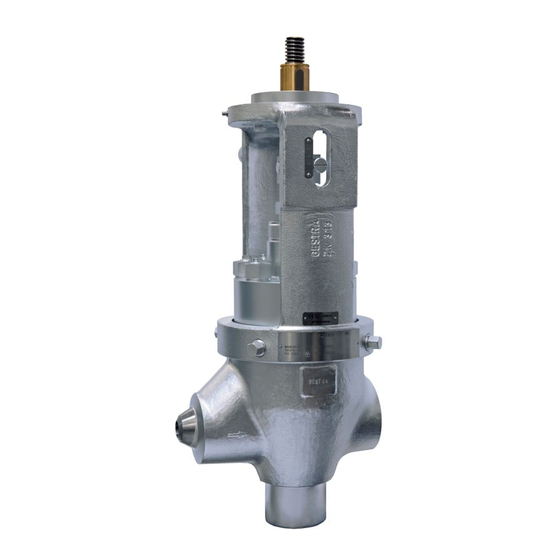
& operating manual for future reference. not described in this installation & operating manual (IOM). Equipment specification Example of type designations The equipment consists of the following main "ZK 313-E/11" components: Equipment with angle-type body and electric rotary Body actuator Upper part "ZK 313-E/20"... - Page 8 In most cases the equipment described in this IOM is of the angle-type and has a spindle bearing for an electric rotary actuator. If any other variant is shown or described it will be explicitly stated. End connections The equipment is available with the following end connections: ...
- Page 9 Component parts Designation Designation Mechanical connection for actuator, in Body equipment with rotary actuator this is a Flow direction arrow (on both sides) spindle bearing (shown here) Name plate Bonnet Upper part...
- Page 10 The yoke is fitted with the following items: Designation Designation Spindle Indicator for scale markings on coupling Coupling Scale Stem (installed in upper part)
- Page 11 The stuffing box seal consists of the following items: Designation Designation Screwed union Support disk Retaining ring Gland packing...
- Page 12 The following items are fitted inside the equipment: Designation Designation Stem Ring Upper part Throttle Upper main gasket Seat bushing Pressure element Valve plug Lower main gasket...
- Page 13 Equipment with spindle bearing features a bonnet that is provided with a grease nipple. Designation Grease nipple (only on actuator with handwheel or electric rotary actuator)
- Page 14 Name plate Application of European Directives The following items are indicated on the name Pressure Equipment Directive plate: The equipment conforms to this Directive (see Manufacturer "Declaration of Incorporation" section) and can be Type designation used for the following media: ...
-
Page 15: Task And Function
Task and function Purpose The equipment is designed to reduce pressure in pipes through which the following fluids flow: water steam condensed water In addition the equipment can control the flowrate and the fluid level. The equipment can stop the fluid flow completely, effecting a pipe seal to attain bubble-tight shut off. -
Page 16: Storing And Transporting The Equipment
Storing the equipment Then the plug is lifted off its seat by the retaining ring (26). The equipment is now open. Please observe the following items when storing the equipment: Make sure that the equipment is completely disconnected. ... -
Page 17: Transporting The Equipment
Transporting the equipment If you do not have the sealing plugs supplied with the equipment use appropriate seal caps to seal off the DANGER connections. Risk of bruises if the equipment or For short distances (only a few metres) you can component parts fall down. -
Page 18: Mounting And Connecting The Equipment
Preparing installation Mounting and connecting the equipment Remove the transport packaging. Check the equipment for transport damage. DANGER If you detect any transport damage, please contact the manufacturer. Risk of bruises if the equipment or When supplied by the factory, the connections may component parts fall down. -
Page 19: Connecting The Equipment
Connecting the equipment The equipment is designed for installation with the stem in vertical position and the actuator mounted on top. DANGER Other installation positions are possible. Incorrectly connected equipment can result Contact the manufacturer if you want to in accidents with extremely severe injuries mount the equipment in a different or death. -
Page 20: Checking The Function
Checking the function Make sure that only qualified personnel carries out the heat treatment. Make sure that the equipment is safely mounted After the heat treatment you may insulate the and that all connections are made correctly. equipment if necessary. -
Page 21: Operating The Equipment
Operating the equipment After operation Do not work on the equipment while it is operating. DANGER DANGER If the equipment is used in contaminated areas there is a risk of severe injuries or Risk of bruises when working on the death caused by harmful substances in or equipment during operation. - Page 22 For more information on suitable protective clothing and safety gear refer to the safety data sheet of the fluid in question. DANGER Risk of bruises when working on the equipment during operation. Switch off the equipment if you have to work close to any moving equipment parts.
-
Page 23: Maintaining The Equipment
Maintaining the equipment Maintenance schedule Interval Component Activity 2 months Stem Move stem by at least one complete stroke. 3 months Stuffing box seal Visually inspect to ensure tightness. Retighten a leaky stuffing box, replace if necessary. Visually inspect the following points: ... -
Page 24: Rinse The Equipment
Rinse the equipment Lubricating the equipment Rinse the equipment in order to remove any dirt Attention! particles or fluid residues inside the equipment. Equipment may be damaged if unsuitable lubricant is used. DANGER Use only specified lubricants. Personnel working on pipes are exposed to safety risks and may suffer severe injuries, ... - Page 25 Preparing equipment for rinsing Attention! Remove all parts from the body before rinsing the equipment. Equipment may be damaged by unsuitable Disassemble the equipment as described from cleaning fluid. page 26onwards. Rinse the pipe with the same fluid that ...
-
Page 26: Disassembling The Equipment
Use only tools of suitable size. To remove and mount internal parts you must use the "Tool kit for removing internals" for valves of type ZK 313. To order the tool kit please state the following stock code number: 368220... - Page 27 The space required for disassembling and DANGER re-assembling the equipment depends on the optional extras and the type of Risk of bruises if the equipment or actuator. component parts fall down. For more information on the required service space see the attached drawings. ...
- Page 28 Loosen the hexagon nuts (27) on the coupling. You can now remove the mechanical connection for the actuator. Remove the hexagon-head cap screws (28) and the locking washers (29). For equipment with an electrical rotating motor, you must remove the spindle bearing and spindle. ...
- Page 29 Remove the two hexagon head screws (34). Removing the bonnet The attachment of the bonnet to the body The following drawing shows the depends on the type of actuator. equipment with actuator bearing for an Valves with pneumatic actuator feature a electric rotary actuator.
- Page 30 Removing the bonnet of equipment with pneumatic actuator If the equipment is fitted with a pneumatic actuator, the bonnet (here called yoke) is an elemental part of the actuator. In this type of equipment the bonnet is called "yoke". In order to distinguish the yoke more clearly from the standard bonnet, the following drawing shows the actuator.
- Page 31 Removing the upper part The following components are removed together with the upper part. Stem (9) with plug Stuffing-box packing with screwed union (12) Unscrew the hexagon nuts (39) on the upper part (1.) Loosen the screwed-union (12) until you can move the stem (2.).
- Page 32 Choose the extraction device according stud bolts. to the specification in the "Tool kit for document removing/mounting internals for valves of type ZK 313 " (4-ZK 428). In this document you will also find information on how to remove internals from hammer-forged bodies.
- Page 33 Put the extraction device (41) together with the adapter (42) into the seat bushing. Use a spanner (US: wrench) to retain the extraction device. Turn the adapter clockwise until the extraction device is securely seated. The extraction device is now firmly clamped in the seat bushing.
- Page 34 Insert the spindle (45) through the bore in the yoke (43) (2.). Screw together the spindle and the extraction device (41) (3.) Screw the hexagon nut (46) handtight onto the spindle (4). To lift the seat bushing and the other internals off the body, slowly fasten the hexagon nut.
- Page 35 Removing the gland seal You only have to dismount the stuffing box if you want to exchange parts of the stuffing-box packing. To dismantle the stem and the plug you do not have to remove the stuffing box. To remove the stem loosen the stuffing box.
- Page 36 Take the packing gland (47) out of the upper Removing the plug and disc springs part. The retaining ring connects the plug with the stem. Take the packing rings (15) of the packing gland The retaining ring can be accessed via the gap out of the upper part.
- Page 37 Clamp the stem (9) in the clamping device. Force the plug (23) into the stem. Use a suitable device to hold the plug in this position. Use a screwdriver to lever the retaining ring (26) out of the groove in the stem (9). ...
-
Page 38: Assembling The Equipment
Assembling the equipment CAUTION Work prior to re-installation Operating personnel may get injured if the disc springs are decompressed in an CAUTION uncontrolled manner. Sharp edges on component parts can Always wear sturdy work gloves and cause cuts. safety goggles when working on the stem and plug. - Page 39 Attention! CAUTION Equipment may not work properly or get Operating personnel may get injured if the damaged if parts are tilted or skewed disc springs are decompressed in an when installed. uncontrolled manner. Use suitable lifting gear to mount the ...
- Page 40 Clamp the stem (9) into the jaws of the Installing inner parts clamping device. DANGER Use a suitable device to force the plug (23) into the stem (1.). Risk of bruises if the equipment or Fix the plug in this position. component parts fall down.
- Page 41 Put the seat bushing (22) into the body (1.). Put the ring (20) with the groove over the shoulder on the seat bushing (2.). Place the lower main gasket (19) on the ring (3.). You can also assemble the insert outside of the valve body and then use the extraction tool kit to fit it in the valve body.
- Page 42 Mounting the gland packing Attention! Malfunctions may occur if the packing rings are fitted incorrectly. Make sure that the packing rings (15) of the stuffing box are inserted in the following order: one wiper ring made from graphite and CrNi ...
- Page 43 Screw the screwed union (12) loosely into the upper part. Put the packing ring (15) into the screwed union. Put the support disk (14) into the screwed union. Put the retaining ring (13) into the groove of the screwed union.
- Page 44 Fitting the upper part The torque required for tightening the screwed union depends on the condition of the stuffing-box packing. Tighten the screwed union until the DANGER following requirements are met: Risk of bruises if the equipment or The stuffing box must not leak. component parts fall down.
- Page 45 Attaching the cap and actuator Mounting the bonnet Put the bonnet (2) onto the body with upper This section describes installation in part. standard equipment. Apply MoS2 grease to the threads of the grub In equipment with a pneumatic actuator, screws (35).
- Page 46 The torque depends on the type of actuator: Handwheel operation and rotary actuator ZK 313/11: 50 Nm Electric rotary actuator ZK 313/12: 200 Nm In equipment with rotary actuator put the spindle bearing (33) with the spindle (7) screwed in place onto the yoke.
- Page 47 For reasons of clarity, the following drawing shows the equipment without the actuator. Put the actuator onto the bonnet. Insert the stud bolts (30) through the spindle bearing and the bonnet in the actuator. Fix the stud bolts with washers (31) and nuts (32).
- Page 48 Mounting the coupling Rotate the spindle (7) and the stem (9) so that they lie flush against one another without pressure. Place the two halves of the coupling (8) around the stem and spindle as shown. Secure the spindle and coupling parts with a hexagon head bolt (28).
- Page 49 Fit the cap and pneumatic actuator. If the equipment is fitted with a pneumatic actuator, the bonnet (here called yoke) is an elemental part of the actuator. In this type of equipment the bonnet is called "yoke". DANGER Risk of bruises if the equipment or component parts fall down.
-
Page 50: Servicing The Equipment And Installing Spare Parts
Connecting the actuator Connect the actuator properly to its power supply. Servicing the equipment and installing spare parts You may exchange the following component parts in case of wear or damage: The material specification and stock code numbers of the component parts are indicated in the supplied parts list. -
Page 51: Troubleshooting
Troubleshooting Problem Cause Remedy The stem moves with difficulty Malfunction in actuator. Follow the instructions in the operating or jerky. manual for the actuator. The actuator switches off Malfunction in controller. Follow the instructions in the operating automatically. manual for the controller. The stuffing box packing Slightly loosen the stuffing-box screw. -
Page 52: Putting The Equipment Out Of Operation
Putting the equipment out of Caution operation Environmental damage may be caused by Removing harmful substances poisonous fluid residues. Before disposing of the equipment DANGER make sure that it is clean and free of fluid residues. If the equipment is used in contaminated ... - Page 53 DANGER WARNING Risk of bruises if the equipment or Risk of severe injuries or death if the component parts fall down. actuator is not removed correctly. Always wear protective gear when Before working on the actuator cut off working on the equipment.
-
Page 54: Disposing Of The Equipment
Disposing of the equipment Caution Environmental damage may be caused by poisonous fluid residues. Before disposing of the equipment make sure that it is clean and free of fluid residues. For the disposal of all materials observe the pertinent legal regulations concerning waste disposal. -
Page 55: Fluid Flowrate And Differential Pressure
Fluid flowrate and differential pressure Flowrates, cold water Differential pressure Flowrate... - Page 56 value value 12.7 15.0 23.1...
- Page 57 Flowrates, hot water, ts–5 K Differential pressure (assuming discharge to atmospheric pressure) For higher back pressure take a correction factor into account. The ascertained flowrate is reduced by the correction factor. Flowrate value value 12.7 15.0 23.1...
-
Page 58: Pressure & Temperature Ratings
European Directives in our Declaration of Conformity or our Declaration of Incorporation. To request the valid Declaration of Conformity or Declaration of Incorporation, please contact: GESTRA AG Münchener Straße 77 Correction factor 28215 Bremen Pressure ratio p2/p1 (absolute) - Page 60 Agencies all over the world: www.gestra.de GESTRA AG Münchener Straße 77 28215 Bremen Germany Telefon +49 421 3503-0 Telefax +49 421 3503-393 E-Mail info@de.gestra.com www.gestra.de 818542-04/07-2017 kx_mm (808600-05) © GESTRA AG Bremen Printed in Germany...
Need help?
Do you have a question about the ZK 313 and is the answer not in the manual?
Questions and answers